If your goal is to print overhangs without supports, the answer is yes for most geometry, as long as each overhang stays around 45 degrees from vertical or shallower, the part cooling is doing its job, and your extrusion is calibrated. Steeper features like bridges need tuned settings, not luck.
Support-free printing is the default goal for most FDM work. It is faster, it wastes no filament on scaffolding, and it leaves no scars where a support was scraped off. The catch is that “support-free” is a description of geometry, not a switch in the slicer, and the angle that actually works varies by filament, nozzle and machine.
Table of Contents
- What You Need
- How to Print Overhangs Without Supports: Step by Step
- Step 1: Prepare and Orient the Model to Print Overhangs Without Supports
- Step 2: Choose the Right Print Orientation and Slicing Profile
- Step 3: Tune Bridging and Overhang Settings
- Step 4: Set the Printer and Verify the First Layers
- Common Mistakes
- Drooping and curling are two different failures
- Treating bridges as overhangs
- Rough, scalloped undersides
- Layer shifts while printing overhangs
- Weak corners and cracked corners
- Using support-free printing as a rule instead of a method
- Skipping experimental geometry that solves the problem
- Frequently Asked Questions
- Can all 3D printing overhangs be printed without supports?
- What is the maximum overhang angle most FDM printers can handle?
- How do I improve bridges on a printed overhang?
- Are support-free prints weaker than prints using supports?
- Does material choice affect support-free printing?
- When should I use supports instead of changing slicer settings?
- Conclusion
What You Need
Before changing a single setting, you need four things in reasonable shape. Get these right and the overhang problem mostly solves itself.
- A calibrated printer. Consistent extrusion, a level bed and a clear part-cooling duct path. A machine that underextrudes will droop at angles a tuned one handles easily.
- A filament you have printed with before. PLA, PETG, ABS, TPU and Nylon each behave differently. If this is your first spool, print a small test block first.
- A slicer you actually know. Cura, PrusaSlicer, Bambu Studio and OrcaSlicer all handle overhang logic differently, and the setting names matter later in this guide.
- A model with manageable geometry. Look for long flat ceilings, wide horizontal arms and thin vertical spikes. If the model has those, reorienting it will do more than any slicer setting.
- Basic prep tools if you work in the slicer: the measure tool for reading angles, a supports or modify menu for splitting a model in half, and a way to look at the layer preview from below.
A word of caution on terminology, because this trips up almost every beginner. An overhang has material beneath it on one side only. A bridge has material on both ends and nothing beneath it. A corbel is a stepped overhang where each layer sits back from the last, which is a completely different problem. Most “my overhangs are drooping” complaints are actually bridges, and bridges have their own settings.
How to Print Overhangs Without Supports: Step by Step
Step 1: Prepare and Orient the Model to Print Overhangs Without Supports
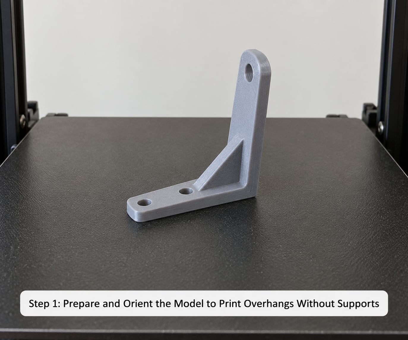
Orientation does more work than any other step, and it costs nothing. Rotate the model until as little surface as possible faces downward, because every downward-facing horizontal surface is a candidate for support.
Three moves cover most models. First, tip the part onto its side so an overhanging arm becomes a vertical column. Second, drop a chamfer or a two-millimetre fillet onto sharp 90-degree lips in your CAD software, which turns an unsupportable edge into a gradual slope. Third, split the model in half with the slicer’s cut tool, print the halves separately, and join them after.
The third option gets more attention than it deserves. A figurine built as two halves saves hours of support material and needs nothing more than a flush-cut spatula and a bit of sanding to join. A user on the Maker Forums community made exactly this point in practical terms: a one-millimetre span printed straight across with no support at all, because the geometry was short enough.
Before you commit, use the measure tool in your slicer to check the two or three steepest features against the build plate. Sliders are poor angle judges. A 10-degree error in your mental estimate is the difference between a clean print and a scrapped one.
Step 2: Choose the Right Print Orientation and Slicing Profile
Where you have a choice, print the part in the orientation that keeps the functionally important dimensions vertical. A bracket that mates with another bracket has one face that must stay flat, and that requirement usually wins over a nicer overhang profile.
Layer height is the quiet lever here. Each layer is offset sideways from the one below by the layer height multiplied by the tangent of the overhang angle, so thinner layers shift the supported fraction of the bead in your favour. The rule of thumb used to be that half the bead width must stay attached to solid plastic, which gives the familiar formula: supported fraction equals 1 minus (h multiplied by tan theta) divided by w.
Run that arithmetic and the 45-degree rule stops being folklore. At 0.2 mm layer height with a 0.4 mm bead, the offset reaches half the bead at exactly 45 degrees. At 0.3 mm layers the same half-bead point arrives near 34 degrees, which is why the same model can print at one layer height and sag at another. This is also the answer to whether you can run a 0.2 layer with a 0.4 nozzle: you can, and overhangs will actually behave better for it.
For a start profile, run a 0.2 mm layer on a 0.4 mm nozzle, two perimeters and 15 to 20 percent infill. Then open the preview, switch to the layer view and orbit underneath. Look specifically for layers where the whole extrusion line is floating with nothing touching it below.
Step 3: Tune Bridging and Overhang Settings
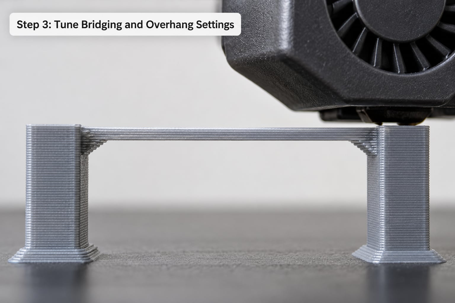
Cooling and speed do the heavy lifting on any surface printed into open air. Most of what people mean when they ask how to print overhangs without supports is decided right here rather than in the model file. Work through these in order and change one thing at a time, because three changes at once tell you nothing about which one worked.
- Set part cooling to 100 percent from the layer the first overhang appears, not from the start of the print. Bridging fan in PrusaSlicer and OrcaSlicer does this automatically once you mark a region as a bridge.
- Slow the outer wall down. Around 20 to 25 mm/s is a common target for PLA on a 0.4 mm nozzle. Give the plastic time to set before the nozzle returns to pull the string off the end.
- Drop bridging speed harder than wall speed. Roughly 15 to 20 mm/s works for short spans in PLA. Longer bridges want slower still.
- Reduce extrusion width to around 50 percent on bridge lines. A Prusa forum thread on angled overhangs near the bed put it plainly: about 50 percent gets you most of the way, and a little more is possible when heating and cooling are balanced.
- Widen bridge lines slightly in the other direction if you want strength, not surface quality. Bridges and overhang perimeters are different animals. Extra perimeters help a long unsupported span hold, while a thinner line helps a short one look clean.
- Add more perimeters to horizontal tops, not infill. Infill adds strength downward. Perimeters add the shell that keeps an overhang from peeling.
Typical maximum overhang angles, measured from vertical, on a well-tuned machine. Angles in degrees.
| Material | 0.4 mm nozzle | 0.6 mm nozzle | 0.8 mm nozzle | Watch for |
|---|---|---|---|---|
| PLA | 50 to 60 | 55 to 60 | 55 to 60 | Best flowing overhang of the common filaments; can string on long bridges |
| PETG | 40 to 50 | 45 to 50 | 45 to 50 | Stiffens fast, so it holds earlier but droops sharply when it does let go |
| ABS | 40 to 45 | 40 to 45 | 40 to 45 | Needs an enclosure or it warps before it can sag |
| TPU | 35 to 40 | 35 to 40 | 35 to 40 | Soft and flexible, so the tolerance is set by stiffness, not adhesion |
| Nylon | 35 to 45 | 35 to 45 | 35 to 45 | Absorbs moisture, which changes viscosity and shortens the cooling window |
A wider nozzle helps. The bead is wider, so more of it stays anchored at the same angle, and the extrusion has more mass to resist the pull of gravity. If you have a 0.6 mm nozzle and a fine-detail model, checking the overhang preview at coarse layer height is worth the two minutes.
Corbelling pushes the numbers much further. Each layer of a corbel is stepped back by a small angle, commonly 15 to 18 degrees, so nothing in the print is ever truly horizontal. A well-formed corbel can hold at wall angles that would collapse as a flat overhang. The trade-off is internal space and surface ripple on the visible face.
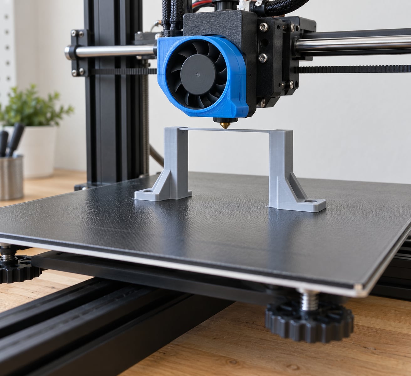
On bridges specifically, keep the span short. Five millimetres or less of free span usually prints unaided, and the same span at fifteen millimetres is a coin flip. If the geometry forces a long gap, the honest answer is that a bridge infill pattern, a tower, or support is the right tool.
Step 4: Set the Printer and Verify the First Layers
The settings above only pay off on a machine that extrudes predictably and holds temperature. That is not a criticism of your printer, just the reality of the process.
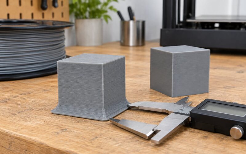
Run a flow or extrusion calibration cube. Look at the sides for consistent width, the top for gaps between lines, and the bottom for a solid face. If lines are inconsistent, every overhang angle in the table above moves, because the bead is not the width the slicer thinks it is.
Nozzle temperature matters more than most guides admit. A few degrees low and the bead arrives with less thermal energy, so it bonds to the layer below more weakly and the overhang is already compromised before cooling starts. For PLA, run your normal high-quality temperature rather than a speed temperature.
Keep the part-cooling duct aimed where the model needs it. Ducts that blow across the nozzle instead of past the fresh layer waste a lot of cooling on plastic that has already set.
Z-hop and retraction are not overhang settings, but they are adjacent. If a string is being pulled off a bridge, extra retraction and a 0.4 to 0.6 mm Z-hop will keep that string from welding into the surface below. Bed adhesion belongs in the same conversation: a part that lifts at layer 60 has no chance at layer 120.
Watch the first overhang layer like a hawk. A good one looks slightly rounded underneath with a clean first line and no strings. A bad one shows a sagging lip, a visible gap under the leading edge, or a wrinkle at the corner. Stop the print at that point and change one setting.
Common Mistakes
Drooping and curling are two different failures
A drooping overhang hangs down and rounds off underneath. The bead was too hot, too slow, or not cooled enough, and gravity won before the plastic set. Fix it with more part cooling, a slower outer wall, thinner layers, or a geometry change.
A curling overhang lifts up at the edges and pulls inward, sometimes catching the nozzle on the next pass. That is a different animal. It usually means the leading edge has curled while the nozzle is still travelling across the previous layer, so the fix is speed and flow rather than cooling alone. More cooling helps, but so does reducing flow for overhang perimeters and raising the speed slightly on the following layer so the nozzle is not dragging through softened plastic.
Treating bridges as overhangs
A bridge has no support under any of it, so the 45-degree rule says nothing about it. Apply the bridge settings: maximum cooling, slow bridge speed, thin bridge lines and a short span.
Rough, scalloped undersides
Scallops on the underside of an overhang come from the layer height outrunning the part cooling. Either thin the layers or increase airflow. Raising the fan without thinning layers often just makes the edges crisper while the middle still droops.
Layer shifts while printing overhangs
A layer shift during a long bridge is usually a knock-on from something else, often a collision with a curled edge, a loose belt or a bed that has cooled below adhesion. Diagnose the first bad layer, not the shift.
Weak corners and cracked corners
Corners on overhang-heavy parts are stress concentrators. Add one extra perimeter on those layers, slightly increase infill locally, and round the corner in CAD. Corners fail at a much lower load than people expect.
Using support-free printing as a rule instead of a method
This is the mistake that costs the most filament. Two habits help. First, run an overhang test model on your own machine, in your own filament, and record the angle where the underside first goes rough. That number is your real limit, and it beats any table.
Second, a user printing a 12-inch auger on a MakerBot Replicator Z18 at 0.2 mm layers with two shells and 10 percent infill reported sag under each flight with no supports, and rough edges when printed horizontally with supports instead. Neither route was clean. Reorienting the part so the flights were not the weak surface would have been the third option, and the one nobody tried.
Skipping experimental geometry that solves the problem
Arc and wave overhang geometry is worth knowing about even if you never use it. Instead of stacking flat layers, the surface is filled with concentric arcs that fuse sideways into each other rather than downward onto air. The technique holds very steep angles without support, at the cost of print speed in the range of 2 to 5 mm/s and a visibly ridged underside.
Related ideas include conical slicing, which tilts layers into cones, and corbelling, which steps each layer back. All of them trade time and surface quality for a cleaner underside on steep geometry. For a quick part on a plate that is already proven, none of them beat simply rotating the model.
Frequently Asked Questions
Can all 3D printing overhangs be printed without supports?
No. Anything steeper than roughly 45 degrees from vertical, or any surface with nothing beneath it at all, needs special settings or geometry changes. Most real models have a mix. A mechanical part with a 60-degree rib or a figurine with a 30-millimetre gap will need reorienting, chamfering or genuine support material. The useful mindset is that each feature gets the treatment it needs rather than a blanket yes or no.
What is the maximum overhang angle most FDM printers can handle?
Around 45 degrees from vertical on a well-tuned PLA machine, with 50 to 60 degrees being achievable on a calm, well-cooled print. Thinner layers help, because each layer is offset by less. Wider nozzles help, because a wider bead keeps more of itself anchored. Test your own limit with an overhang tower rather than trusting a table, since every machine and every spool prints a little differently.
How do I improve bridges on a printed overhang?
Run the part cooling fan at full speed on bridge layers, drop bridging speed to roughly 15 to 20 mm/s, and set bridge extrusion width near 50 percent. Keep the free span under about five millimetres where you can. Bridging fan settings in PrusaSlicer, OrcaSlicer and Bambu Studio handle the fan trigger for you once the line is marked as a bridge. Longer gaps want a slower speed and a different strategy entirely.
Are support-free prints weaker than prints using supports?
The overhang surface itself is often stronger support-free, because the underside fuses directly to the layer below with no support interface. What weakens a part is layer adhesion overall, not support use. Support-free parts often end up weaker in bending because the unsupported surfaces are rougher and act as stress concentrators. If load matters, add a perimeter and inspect the part rather than adding support material for strength alone.
Does material choice affect support-free printing?
It affects everything. PLA flows well and holds the steepest angles of the common desktop filaments. PETG stiffens fast, so it can look perfect and then drop suddenly. ABS and Nylon need an enclosure to avoid warping before sagging even becomes the issue. TPU is soft enough that the limit comes from stiffness rather than adhesion. Expect roughly 45 to 50 degrees for PETG and 35 to 45 for Nylon on a 0.4 millimetre nozzle.
When should I use supports instead of changing slicer settings?
Use supports for long bridges, deep ceilings, faces and hair on minis, and anything that a failed print would ruin. Also use them when the part has to be dimensionally accurate on a face that support material would scar. Soluble HIPS with PLA, or PVA in a dual-material machine, dissolves the interface and leaves a much cleaner surface. If the geometry is difficult, supports are a tool rather than a failure.
Conclusion
To print overhangs without supports, start with orientation rather than settings. Rotate the part so the steep surfaces are not facing down, add a chamfer if you control the model, and cut the part in half if that solves it. Then open the preview from underneath and identify anything genuinely floating.
Next, set part cooling to full on overhang and bridge layers, slow the outer wall and bridge speeds, and set bridge extrusion width near 50 percent. Run a flow calibration first if you have not, because a wrong extrusion width makes every angle number above wrong too. From there, make one change at a time and let the first overhang layer tell you whether it worked. When the geometry refuses to cooperate, reach for support material without feeling like you lost.