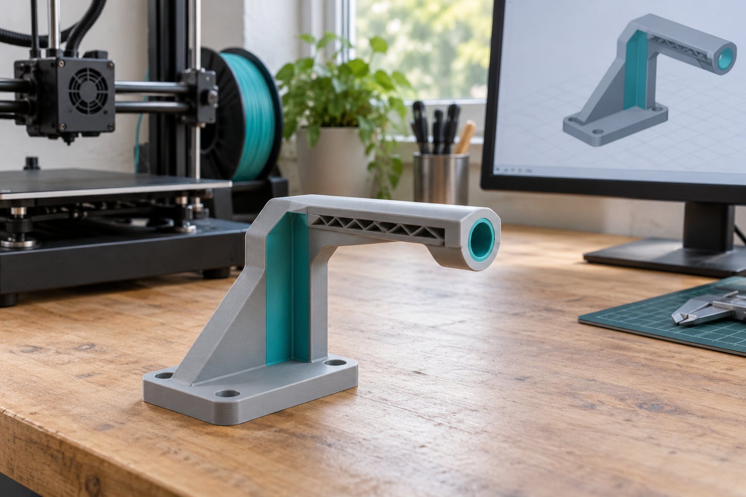
Designing parts that print without support comes down to three moves: orient the model so its largest faces sit on the build plate, reshape anything steeper than about 45 degrees from vertical, and turn flat unsupported spans into bridges anchored at both ends. Most models that arrive buried under slicer-generated trees can be fixed in the CAD program in 15 to 30 minutes. The redesign usually pays back an hour of print time plus the entire fiddly removal job that follows it.
Support-free design is not a single trick. It is a habit of asking, before anything else, whether the printer can build that surface with nothing underneath it — and if not, whether a tilt, a chamfer, a split, or a rotation removes the problem before it ever reaches the slicer.
Five costs disappear at once when you redesign rather than support. You stop wasting filament on scaffolding, you stop burning hours of machine time, you stop marring surfaces that matter, you stop fighting supports that fused to the part, and you stop dealing with cavities no pair of pliers can reach. Any one of those is usually reason enough on its own.
Table of Contents
- What You Need
- Step-by-Step: How to Design Parts to Avoid Supports
- Step 1: Inspect the Part and Identify Support Traps
- Step 2: Choose a Print Orientation That Minimizes Overhangs
- Step 3: Replace Unsupported Geometry With Printable Features
- Step 4: Design Bridges and Self-Supporting Overhangs
- Step 5: Split the Part Into Support-Free Modules
- Step 6: Account for Print Orientation and Material Behavior
- Step 7: Check Clearances, Walls, and Structural Strength
- Step 8: Test the Redesign Before Printing the Full Part
- Common Mistakes
- Treating every overhang as a bridge
- Overlooking drainage in enclosed volumes
- Creating inaccessible cavities
- Adding excessive chamfers
- Weakening the part while redesigning
- Trusting 45 degrees blindly
- When support is unavoidable, design it into the model
- Frequently Asked Questions
- What angle can be printed without supports?
- How do I avoid supports in FDM printing?
- Why do my bridges need support?
- What is the best way to remove support material from a 3D print?
- Should I redesign my part instead of using supports?
- Conclusion
What You Need
You need four things before you start: the model, a way to change it, a way to check it, and a realistic picture of your own printer.
- The parametric source file if you have one. A STEP or native CAD file lets you change a fillet size in seconds, whereas a downloaded STL forces you to model the fix from scratch.
- A CAD tool. FreeCAD, Fusion 360, Onshape, SolidWorks, Inventor, Shapr3D, Tinkercad, OpenSCAD and CadQuery all handle chamfers and fillets; the difference is how painless the operation feels.
- A slicer — PrusaSlicer, OrcaSlicer, Cura or Bambu Studio — to preview overhangs and check the result before committing machine time.
- Your printer’s honest limits: nozzle diameter, typical layer height, travel speed, part cooling, and the materials you actually run. The 45 degree rule is a machine-specific number, not a universal law.
- An overhang test coupon, printed once. A small tower of ledges at 30, 40, 45, 50 and 55 degrees tells you the real limit of your setup in about 20 minutes of print time.
- Calipers and flush cutters for measuring existing parts so the redesign does not break a fit.
That last item is worth doing before you touch anything. I have broken more press fits by “improving” clearance than by leaving a support mark.
Step-by-Step: How to Design Parts to Avoid Supports
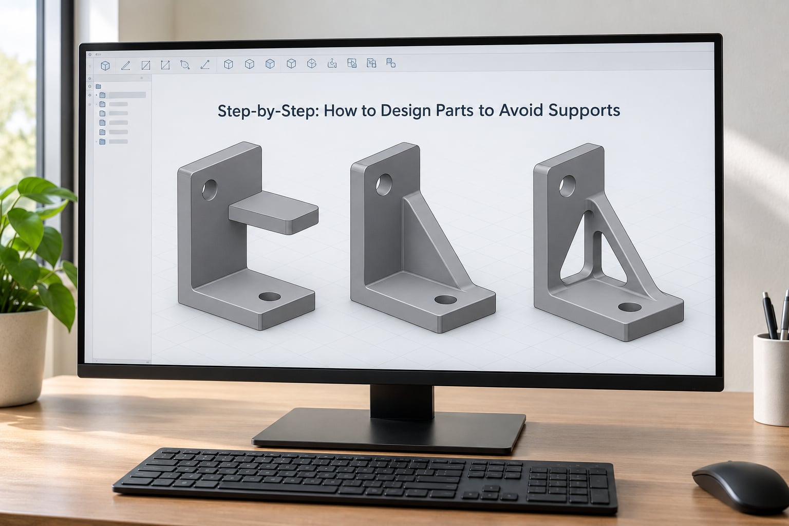
Work through these in order. Most models only need steps 1 and 2. Skip ahead only when you already know the part is trouble.
Step 1: Inspect the Part and Identify Support Traps
Load the model in your slicer, slice it with supports enabled, and look at the preview. The supports themselves are your diagnostic: every one of them is a surface the printer cannot build on its own.
Group what you find into four categories. Horizontal faces with nothing beneath them are the obvious ones. Isolated patches of material with no contact edge at all — islands — are the second. Third, enclosed volumes where resin would pool. Fourth, first-layer contact points: small feet that will either spread or lift off the plate.
Mark the count. On a typical bracket there will be three to six genuine traps, and it is usually easier to attack six than to argue with a thousand automatic supports.
Step 2: Choose a Print Orientation That Minimizes Overhangs
Rotation is free and it removes more support than any slicer setting. The goal is to put the part’s largest, flattest area on the build plate so the maximum number of layers sit directly on material already printed.
Score each candidate orientation on four things: how many support islands it creates, how many layers the part needs, how the main load direction falls relative to layer lines, and where the support marks would land on visible faces. That last criterion is the one beginners skip. If a face has to be glossy and clean, treat any support touching it as a defect and re-orient or redesign.
Watch out for the common disappointment: flipping the part over usually just moves the overhang somewhere else. Rotation solves a problem when the part has one dominant plane. If it still needs support in the new position, move to step 3.
Step 3: Replace Unsupported Geometry With Printable Features
This is where how to design 3D printed parts to avoid supports stops being theory and becomes specific modelling. Three features cover most cases: chamfers, fillets, and hole reshaping.
Chamfer the underside of anything horizontal. A flat bottom face needs a shelf of support underneath it. Replace it with a 45 degree cone, a wedge, or a sloped transition and the face prints at a self-supporting angle with nothing underneath.
Use a fillet carefully. A single fillet on the underside of an overhang can still leave a curved surface pointing down, and curves fail earlier than flat faces. The community fix from the Hackaday thread on support-avoiding design is a double fillet: two smaller radii instead of one large one, which breaks the underside into gentler steps the nozzle can lay down.
Reshape horizontal holes. A round hole drilled sideways has a curved roof that sags. A teardrop hole — a circular bore with a pointed extension in the direction of the overhang — prints on its own because the pointed tip needs almost no material to hold. The same idea works for square holes: add a small roof wedge above the opening.
| Problem geometry | Support-free redesign | Why it works |
|---|---|---|
| Flat underside shelf | Chamfer at 45 degrees or replace with a rib | Surface turns vertical, no material needs to sit under it |
| Sideways round hole | Teardrop hole with the point aimed at the overhang | Tip cross-section is too small to sag before it bonds |
| Horizontal countersink or counterbore | Add a 45 degree lead-in chamfer at the mouth | Blind pockets bridge from the rim instead of resting on support |
| Single fillet under an overhang | Two smaller fillets in series | Each step stays within the printer’s self-supporting angle |
| Curved or hex unsupported span | Break it into straight runs with a rectangular block plus a square insert | Straight runs anchored at both ends print reliably |
Adding the actual features takes a minute in most packages:
| Software | Chamfer | Fillet | Reality check |
|---|---|---|---|
| FreeCAD | Part > Chamfer | Part > Fillet | Select edges by hand; the edge naming trips people up |
| Fusion 360 / Onshape | Modify workspace > Chamfer | Modify workspace > Fillet | Both handle a whole face selection cleanly |
| SolidWorks / Inventor | Features > Chamfer | Features > Fillet | Handles complex edge chains without fuss |
| Tinkercad | Hole tool chamfer setting only | Not available | Beginner-only; redesigns are easier than edge selection |
| OpenSCAD | hull() of offset shapes | minkowski() or hull of circles | Painful on imported meshes; design around it in code instead |
| CadQuery | .chamfer() | .fillet() | Best option if the redesign will repeat across a family of parts |
Step 4: Design Bridges and Self-Supporting Overhangs
Bridging is not overhanging. An overhang is attached along one edge and cantilevers outward; a bridge is attached at both ends with the middle in mid-air. Most guides blur these two, and the confusion is why people build a bridge that droops and assume their printer is bad.
| Factor | Overhang | Bridge |
|---|---|---|
| Attachment | One long edge, like a cantilever | Both ends anchored to existing material |
| Support needed | Yes once it passes the self-supporting angle | No, if the span is short and straight |
| Failure mode | Layers creep outward, corners droop, edges curl | First line lands late or mid-air and sags |
| Design target | Hold 45 degrees from vertical or steeper | Keep spans short, level and consistent |
| Trick that helps | Chamfer, rib, or rotate | Add a mid-span anchor or shorten the gap |
Self-supporting angle means measured from vertical. Straight up is zero degrees, horizontal is 90 degrees, so anything past about 45 degrees starts asking for help. Four variables move that number on your machine: cooling, layer height, print speed and material.
Raising the layer height makes each layer stickier to the one below, so steep angles hold better. Slowing down gives the previous layer more time to cool and grip. Strong part cooling on an enclosed machine helps more than almost anything else. And a tough, warp-resistant filament forgives steeper overhangs than a soft one.
For bridges, the start line is the whole game. Give the span a clean start point on solid material rather than at the very edge of a curved surface, keep the run straight rather than diagonal, and add a mid-span support post if the gap exceeds about 40 mm on a typical desktop machine. Support points spaced along a bridge, not just at the ends, turn a risky span into a reliable one.
Step 5: Split the Part Into Support-Free Modules
Some geometry simply will not cooperate. When that happens, dividing the model into two flatter pieces and joining them after printing is often the right answer, not a compromise.
The joint decides whether this works. A tab and slot, a printed-in pin with a matching socket, a friction fit, or a countersunk screw all hold alignment. Design the joint on the build plate side so it prints horizontally, and give it a small lead-in chamfer so the two halves start together instead of fighting.
The honest downside is assembly time and a seam line. For a display piece that is a dealbreaker. For a jig that spends its life bolted to a table, nobody will ever see the joint.
Step 6: Account for Print Orientation and Material Behavior
FDM and resin behave differently enough that the same redesign does not carry across.
On FDM, the failure mode is sagging and delamination, so anything with enough cross-section at the unsupported tip survives. On resin, the layer is thin and the whole surface is suction-held to the build plate, so material below roughly 2 mm in cross-section gets pulled out of shape. That single fact drives most resin support points.
Resin adds a failure mode with no FDM equivalent: uncured liquid trapped in an enclosed volume. Any pocket, dome or internal channel needs a drainage hole at its lowest point, angled so gravity works even when the part sits in the printing position. Carbon’s orientation guide names this unvented volume problem as one of four conditions that trigger supports, alongside overhangs, islands and first-layer adhesion.
Hand-editing auto-supports in resin still beats accepting them blindly. The usual baseline is a critical angle around 10 to 15 degrees, tightened by hand, with bar-style nubs on cosmetic surfaces so the scar is small and easy to sand.
Step 7: Check Clearances, Walls, and Structural Strength
Removing supports also removes material. The support interface layer is usually printed with a solid infill, so once it comes off you may be looking at a thinned wall or a hole in a load path.
Check three things. Wall thickness at any point a support touched, especially where it is no longer visible. Hole diameters, since support scar and finish work will not rescue a hole that is 0.2 mm undersized. And the load direction: layer lines carry far less strength across themselves than along them, so a redesigned overhang should span in a direction that does not fight the primary stress.
If a section got thin, add a rib on the printable side, thicken the wall, or move to a double fillet rather than accepting a fragile surface. Reinforcement belongs where the part is already self-supporting, so the fix does not reintroduce the problem you just removed.
Step 8: Test the Redesign Before Printing the Full Part
Do not discover a sagged bridge 6 hours into a 14 hour print. Three checks catch nearly everything:
- Sliced preview. Re-slice the redesigned file and confirm the support list is empty or tiny. Any support still generated means you missed a trap.
- Small coupon of the hard feature. Model just the troublesome span at 1:1 and print that alone. Ten minutes here saves a whole evening.
- Fit check. If the part mates with something, print the mating half at full scale before the whole assembly.
Keep the original file. You will almost certainly want to compare versions, and a support-free design is easier to iterate from than a supported one.
Common Mistakes
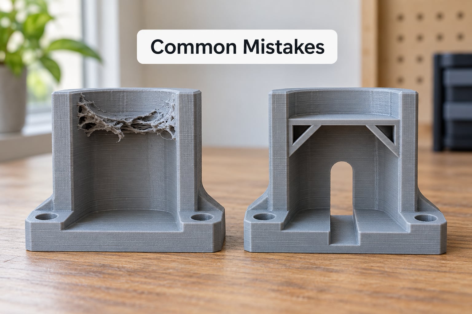
Most support disasters trace back to one of these, and each has a specific design fix.
Treating every overhang as a bridge
If the feature only has material on one side, it is an overhang no matter how short the span looks. Add a second anchor, a mid-span post, or reshape the surface.
Overlooking drainage in enclosed volumes
A resin pocket with no exit traps liquid that then cures into a lump. Add a drainage hole at the low point, angled with gravity.
Creating inaccessible cavities
Support inside a sealed bore cannot be reached with pliers or a flush cutter. No setting fixes this. Move the feature toward an opening or split the part.
Adding excessive chamfers
A chamfer wider than half the wall thickness leaves a thin fragile ridge. Keep chamfers below half the wall and check the remaining section.
Weakening the part while redesigning
Deleting support also deletes the solid interface that was reinforcing that region. Add ribs or thicken the wall on the printable side.
Trusting 45 degrees blindly
45 degrees is a starting point for a well-tuned enclosed FDM machine. Print the coupon and use your real number.
When support is unavoidable, design it into the model
Some parts genuinely need support. One commenter in the community thread on this topic calls the idea of never using supports an oversell, and they are right. A ball joint socket, a ball-and-socket snap, a deep undercut and a suspended cable channel all resist clean redesign.
When you hit one of those, model your own support into the STL instead of accepting the slicer’s. The method that shows up most often in community threads: stand a thin pillar 0.5 to 0.6 mm off the surface, tie it to the part with a deliberately fragile connecting point, and punch it out afterwards. Keep the contact patch as small as you can without the printer tearing it apart. Where you must use slicer-generated supports instead, these are the settings that decide how they release:
| Setting | What it controls | Symptom when wrong |
|---|---|---|
| Z-gap | Vertical separation between support top and the part, usually set as a multiple of layer height | Too small and support fuses to the surface; too large and you get floating scars and rough holes |
| XY-gap | Horizontal offset from the part outline | Too small causes scarring, too large wastes material and weakens thin sections |
| Support interface layer | The solid layer that touches the part and decides the finish | Zero gives a hard, torn removal; several layers pit the surface |
| Support density and pattern | How much material sits under the surface | Too dense is stubborn to remove, too sparse collapses mid-print |
| Normal vs tree supports | Separate trunks versus one branching structure | Tree supports use less material and mark less, but are less predictable on long spans |
| Support contact only | Whether support grows under the whole part or just where it touches | Turning it on cuts material and time but can let overhangs fail sooner |
Frequently Asked Questions
What angle can be printed without supports?
About 45 degrees from vertical is the standard starting point on a well-tuned FDM machine, and most parts hold up to 50 or 55 in practice. The number moves with cooling, layer height, speed and material, so print an overhang test coupon on your own setup before trusting it. Anything at or under that angle needs no support. Steeper surfaces usually do.
How do I avoid supports in FDM printing?
Rotate the part so its largest faces sit on the plate, then reshape anything steeper than 45 degrees from vertical using a chamfer, a rib, or a teardrop hole for sideways bores. Split the model into flatter pieces with a tab and slot joint when rotation cannot fix it. Only reach for slicer-generated supports after those three moves are exhausted.
Why do my bridges need support?
A bridge only works when the nozzle can place the first line across the gap and each later layer bonds to it. Long spans, diagonal runs and curved start points all break that. Shorten the span, start it on solid flat material, keep the run straight, and add a mid-span post above about 40 mm. If the bridge is attached at only one end, it is an overhang, not a bridge.
What is the best way to remove support material from a 3D print?
Set the Z-gap as a multiple of your own layer height rather than copying an absolute number from another profile, and keep the support interface layer thin so it releases without pitting the surface. Flush cutters and a scraper handle most geometry. If support is fused or trapped in an enclosed volume, no technique recovers it, which is the strongest argument for redesigning the part instead.
Should I redesign my part instead of using supports?
Redesign when support touches a cosmetic face, a press-fit hole, a snap fit or an enclosed volume, or when the part is small enough that removal would dominate the job. Keep supports for deep undercuts, ball-and-socket geometry and suspended channels that cannot be reshaped. If a redesign costs more modelling time than it saves in printing, it is not worth it.
Conclusion
Start with the slicer preview, not the CAD program. Slice the model once with supports on and count the supports — that list is your to-do list. Then rotate the part, test two or three orientations against the four criteria above, and only start reshaping once you know rotation cannot finish the job.
From there, the work is repetitive in a good way: chamfer the undersides, teardrop the sideways holes, break curved spans into straight runs, and split anything left into printable modules with a joint you designed rather than one you fought for. Print the hard feature as a coupon first, then commit. That sequence is how how to design parts to avoid supports becomes a habit instead of a rescue job, and it is why so many prints come off the plate clean.