A hotend thermistor is the small temperature sensor buried in the heater block that tells the control board how hot the nozzle actually is. Replacing it takes about an hour, and most of that time goes into careful handling rather than difficult work: test the old sensor, match the specification, swap it, then heat and calibrate to confirm.
If your printer is throwing thermal runaway or MINTEMP errors, bouncing wildly between temperatures, or simply refusing to reach setpoint, the thermistor is the first thing to suspect. This guide walks through the whole job for a typical desktop FDM printer, from picking the right part to proving the reading is accurate afterwards.
Table of Contents
- What You Need
- Tools
- Parts and specifications to confirm
- Step-by-Step
- How to Replace a 3D Printer Hotend Thermistor: Prepare the Printer
- 1. Identify the Old Thermistor and Wiring
- 2. Remove the Hotend or Expose the Thermistor
- 3. Disconnect and Replace the Thermistor
- 4. Reassemble the Hotend
- 5. Run Heater and Sensor Checks
- 6. Calibrate and Test the New Thermistor
- Common Mistakes
- Frequently Asked Questions
- How do I know which component is the thermistor?
- Can I replace a hotend thermistor without soldering?
- Do all 3D printer thermistors use the same wire order?
- Should I calibrate the printer after replacing the thermistor?
- Why does the new thermistor show an incorrect temperature immediately?
- Can a faulty thermistor damage the hotend or mainboard?
- Conclusion
What You Need
Gather everything before you open anything. A missing part halfway through a hotend teardown is how hotends end up sitting on a desk for a week.
Tools
- A multimeter with an ohms setting, for testing the old sensor and confirming the new one
- 2.0 mm and 2.5 mm hex keys, which cover most Ender, Prusa MK3 and E3D V6 hotend hardware
- A Phillips #2 screwdriver for the fan shroud and enclosure screws
- Wire cutters and strippers
- A soldering iron and heat-shrink tubing, only if your sensor has bare wires instead of a factory connector
- Isopropyl alcohol, a lint-free cloth and a small dish or magnetic tray for screws
- Heat-resistant gloves and eye protection, plus a clear work area free of filament and paper
Parts and specifications to confirm
Match the sensor on four things: sensor type, physical form factor, diameter, and connection. Most FDM printers use a 100K NTC thermistor, so that is the safest default, but the form factor is where people go wrong. A glass bead sensor drops into a drilled hole and is held by a set screw. A cartridge sensor slides into a machined bore on E3D V6 and Prusa-style hotends. A 2 mm bead will not seat in a 3 mm hole, no matter how good the electrical spec is.
Part numbers that show up constantly: EPCOS 100k and Semitec 104GT-2 are the common 100K NTC beads, and replacements sold for the Nextruder hotend are 100K NTC too. Check the beta value as well, 3950 being the usual figure and 4066 the other frequent one, because a mismatch bends the temperature curve even though the sensor still reads close to room temperature.
Before you buy anything, measure the old sensor. Readings only make sense near 25 °C, because an NTC is strongly non-linear, so a value taken in a warm room or a cold garage will differ wildly from the datasheet and tell you nothing.
| Sensor or reading | Expected resistance at about 25 °C | What it means |
|---|---|---|
| 100K NTC (EPCOS 100k, Semitec 104GT-2) | Approximately 100,000 Ω | Normal for most FDM hotends |
| 100K NTC with beta 3950 | Approximately 100,000 Ω | Same nominal value, different curve |
| PT100 RTD | Approximately 100 Ω | Only fits firmware set for an RTD |
| PT1000 RTD | Approximately 1,000 Ω | Only fits firmware set for an RTD |
| Heater cartridge, 40 W on a 12 V supply | Approximately 3 Ω | Reference figure, not a thermistor |
| Heater cartridge, 40 W on a 24 V supply | Approximately 14 Ω | Reference figure, not a thermistor |
| Open circuit | Infinite or OL | Thermistor is dead and must be replaced |
| Short to ground | Approximately 0 Ω | Failed sensor or damaged wiring |
The last two rows are the ones worth memorising. An infinite reading on a 100K NTC at room temperature is the classic dead-thermistor signature, and a reading near zero means either the sensor is shorted or a wire is touching the heater block or the frame.
Have the printer documentation open before you start. The manual for your model tells you the sensor part number, whether the connector is JST-XH, Molex Mini-Fit Jr or a bare soldered joint, and how your firmware expects the sensor to be configured.
Step-by-Step
How to Replace a 3D Printer Hotend Thermistor: Prepare the Printer
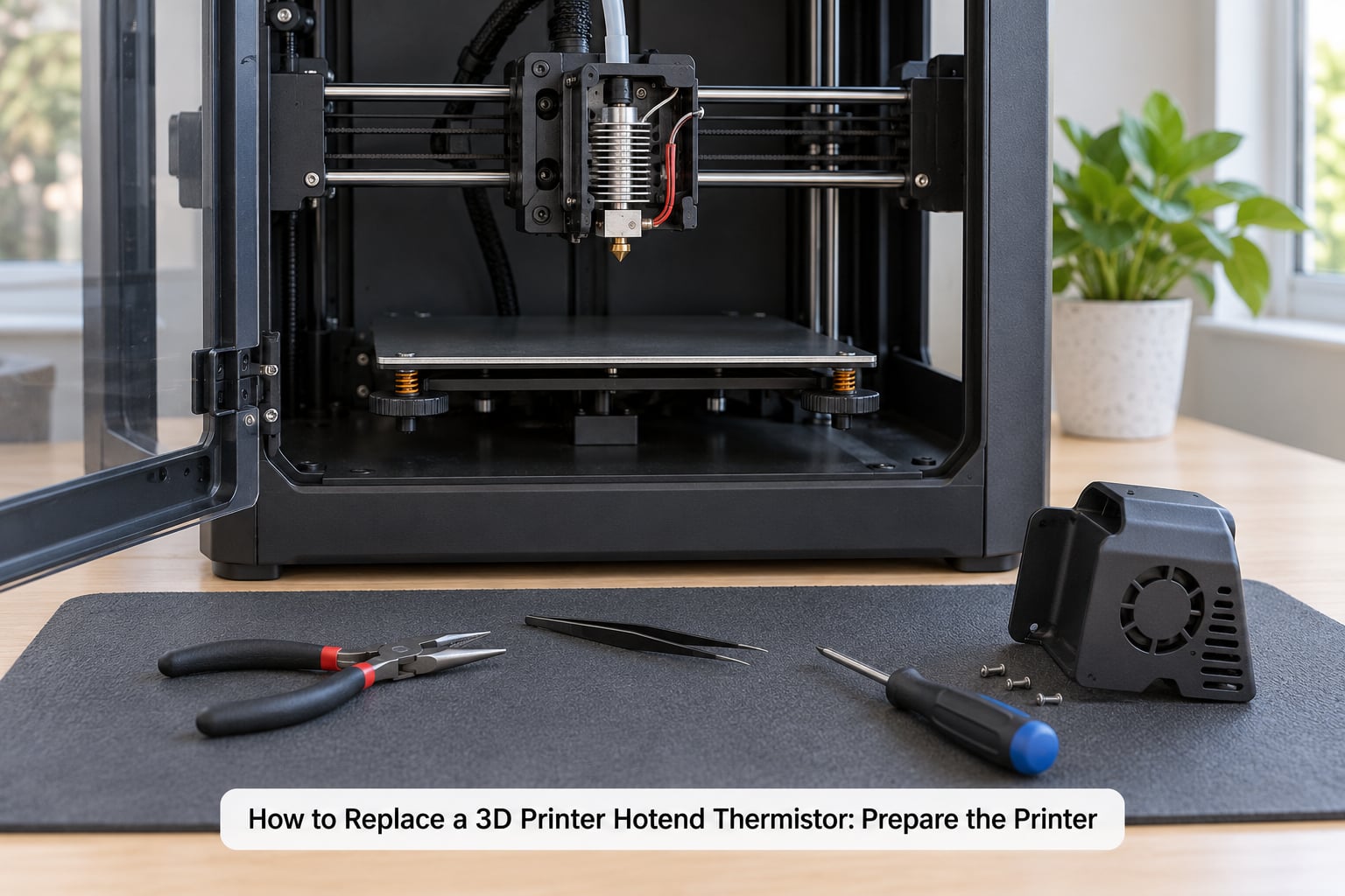
Finish or cancel any running print, then switch the printer off at the front panel and unplug it at the wall. Do not rely on the power switch alone; a live board can still back-feed through the stepper rails on some models.
Let the hotend cool completely, below about 50 °C, before you touch it. A heater block at 200 °C will melt fingers and burn through the silicone sock in seconds, and a dropped hex key into a hot block warps it permanently.
Move the printer to a stable bench where you can reach the hotend from the front and the sides. Clear loose filament, and take a photo of the whole toolhead from two angles before you remove a single screw. That photo is your reference when the wires go back in.
1. Identify the Old Thermistor and Wiring
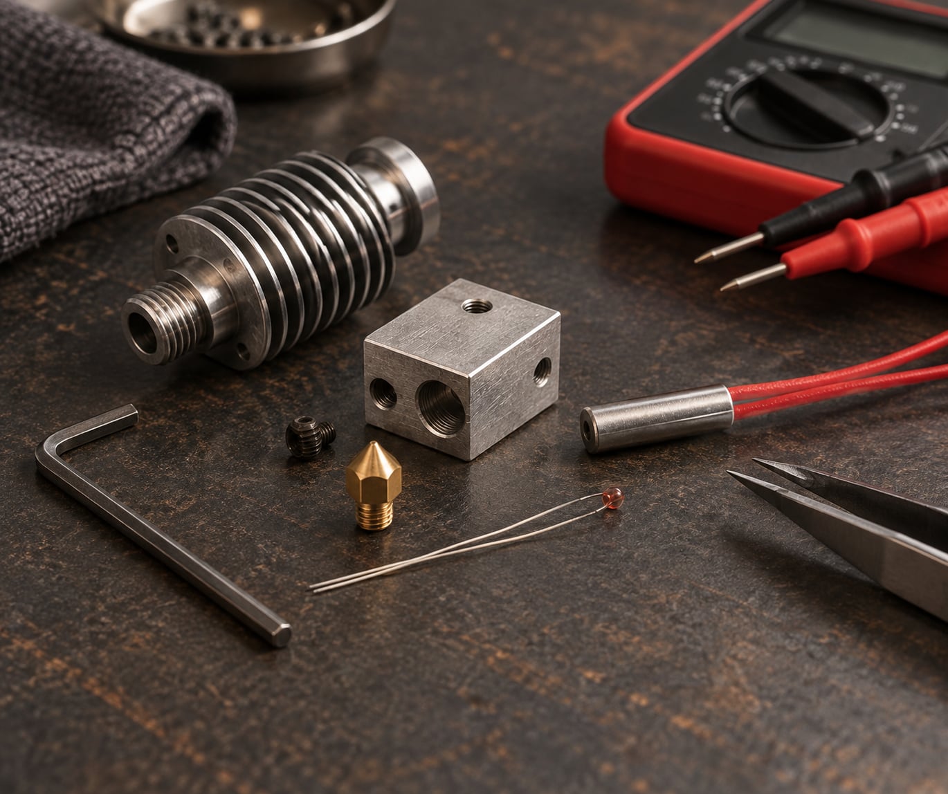
The thermistor is the sensor with two thin wires, usually insulated white, red or black, and a tiny bead or cartridge at the end. The heater cartridge next to it has two thick wires, often red and white, and a metal barrel that screws into the block. The hotend fan wires are three or four and go to a small motor. If you are not sure, the Prusa knowledge base glossary describes the hotend thermistor as a cartridge inserted into the heater block and held by a screw, which is the layout on most machines.
Photograph the connector at the board and the wires at the block, then label them. Wire order is not universal across brands or even across models from the same brand, so treat colour as a hint rather than a rule. Two-wire sensors have no polarity, which makes them forgiving; three-wire PT100 sensors do, and the extra wire must go where the manual says.
If you have a multimeter, this is the moment to use it. Disconnect the thermistor plug, set the meter to ohms, and probe the two sensor terminals. A reading near 100,000 Ω at room temperature on a 100K NTC is normal, and a value that drops when you warm the bead with your fingers confirms a healthy NTC. Infinite or near zero means you have found your fault and can stop guessing.
Touch the thermistor wires while the printer is idle as a quick check too. The readout should settle within a degree or two of the true room temperature. Owners of older Ender machines report idle readings as high as 55 °C in a cool room, and that alone condemns the sensor.
2. Remove the Hotend or Expose the Thermistor
On a printer with a removable hotend, undo the two or three bolts securing the assembly to the X gantry and lift it free. On an enclosed machine you may need to remove the fan shroud or side panel first. Follow the manual for your model rather than assuming the bolt pattern matches another.
Loosen the set screw holding the thermistor in the heater block. Turn it gently and count the turns as they come out, because you will want the sensor at roughly the same depth on the way back in.
Pull the sensor straight out along the axis of the hole. Do not twist the heater block or lever against it, and do not pull on the wires. Those two leads are the weakest part of the assembly, and a break inside the insulation is the reason so many users see temperature readings bouncing long before the sensor gives up entirely.
If the sensor will not come out because of burnt residue or melted plastic, soak the block with isopropyl alcohol and work it free gently rather than forcing it. Some hotends have to be partly disassembled to reach the sensor from behind.
3. Disconnect and Replace the Thermistor
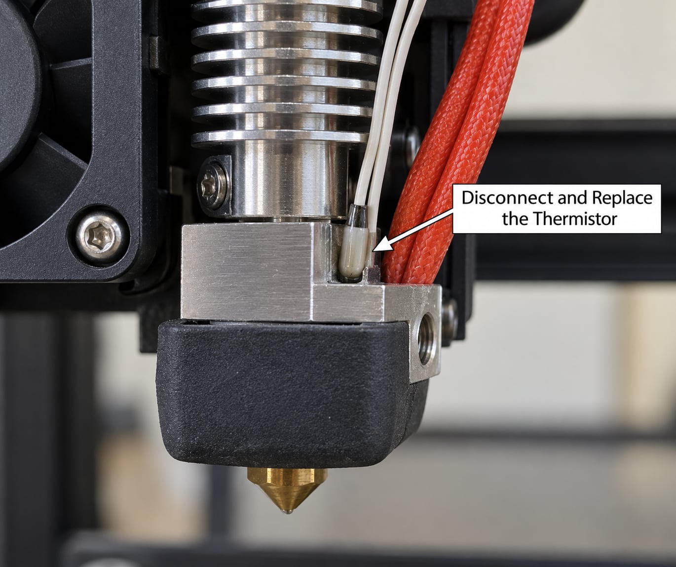
Pull the connector straight off the board or hotend header without rocking it. A JST-XH or Molex Mini-Fit Jr housing has a latch that must be released first; pulling against the latch can deform the housing and cause an intermittent fault later.
Check the new sensor before fitting it. Measure it with the multimeter at room temperature. The reading should be close to the value in the table above, and it should fall when you warm it. A sensor that arrives already out of specification is not worth installing.
Drop the new sensor into the hole until the bead sits flat in the bottom, then start the set screw by hand. Tighten it until it just grips, then a fraction more. This is the step that quietly kills brand-new thermistors. A user on the Prusa forum found a failed sensor on their machine and traced it to a set screw that had been way too tight, and the crushing force cracks the glass bead while leaving the outside looking perfect. Many owners now keep a spare 100K NTC on hand for exactly this reason.
Fit the silicone sock or high-temperature insulating sleeve back over the block, making sure the sensor is under it and not squeezed out of position. Apply fresh thermal paste if the manufacturer uses paste at the sensor seat.
For a bare-wire sensor, cut the new leads to the original length, strip about 5 mm, and solder or crimp to the existing connector. Fit heat-shrink over each joint and the strain relief section. A cold joint or a crimp that only grips the insulation produces a fault that appears and disappears with movement in the cable, which is maddening to diagnose later.
4. Reassemble the Hotend
Route the sensor wires exactly as they were before, using the clips and channels in the hotend body so the cable cannot move when the toolhead travels. Strain relief is the single best protection against a repeat failure. Secure the wires away from the fan blades, the carriage belt and the silicone sock edge.
Reconnect the plug on the board and check it latches fully. A connector pushed in halfway can read fine while the printer is still and fail the moment the bed starts moving.
Refit the hotend assembly, the fan shroud and the nozzle, and tighten every screw evenly. The heater block bolts in particular should be snug and even; a loose block changes how the sensor reads and can look like a drifting calibration.
Check the gap between the heater block and the heatsink. Somewhere between 2 mm and 5 mm is the normal range, and around 2 mm on many Creality models. Too tight and heat creeps up into the cold side of the heat break, which produces runaway errors that look exactly like a faulty sensor.
5. Run Heater and Sensor Checks
Power the printer on and leave the hotend at room temperature for a minute. The displayed temperature should match your room closely. A reading of zero, a wildly high idle value, or a number that drifts on its own all point to a sensor or wiring problem rather than a calibration problem.
Use the heater test in your firmware or controls manual. The menu path differs by board, so go through the printer’s own documentation rather than guessing at a button combination. Watch the reading climb toward the target and settle. It should not stall, overshoot by more than a few degrees, or cycle on and off in short bursts.
Heat to 100 °C first, not straight to 250 °C. A stable 100 °C that holds within a couple of degrees for ten minutes is a good sign. If your firmware supports a test mode that compares the sensor reading against an external probe, use it here, because an independent check is the only way to catch a sensor that reads close to correct but not accurate.
Stop immediately if MINTEMP or MAXTEMP appears. Those cutoffs mean the board is seeing a reading that is physically impossible, which points at the sensor, the wiring or the board header rather than the heater.
6. Calibrate and Test the New Thermistor
Run PID autotune on the printer. On Marlin the command is M303 with a target temperature, followed by the autotune routine and M500 to save; on Klipper you run the tuning macro from the web interface or console. This step is worth doing every time, because the numbers describe how this heater, this block and this sensor behave together, and all three have just changed.
If your firmware supports M900 multi-point temperature calibration, follow that wizard too. It stores a correction curve so slicer temperatures match the real temperature, which matters most on all-metal hotends where the gap between the sensor and the nozzle matters most.
If you changed the sensor type, for example swapping an NTC for a PT100, update the firmware. Marlin reads the sensor selection in Configuration.h as a THERMISTOR_TYPE value for the hotend, and Klipper sets heater_type and sensor_type in printer.cfg. Recompile and reflash before you judge whether the new sensor works.
Finish with a test print: a temperature tower to confirm layer bonding, or a small calibration model to check dimensional accuracy. If the new sensor is a poor fit for the block, layer height will change noticeably between the low and high temperature sections of a tower.
Common Mistakes
- Reversed or swapped wires. Two-wire thermistors are not polarised, so a swap will not hurt. Three-wire PT100 sensors are, and a reversed one shows a fixed wrong offset rather than a total failure. Recheck your photo from step 1.
- Poor crimps and cold joints. A connection that only grips insulation, or a solder joint made on a moving wire, fails intermittently. Pull-test each wire gently and re-do any that move.
- Squeezing the set screw. Too much torque cracks the glass bead. The screw needs to grip, not clamp, and this failure is documented on the Prusa forum as a cause of a sensor that died within weeks.
- Crushed or unrouted leads. Wiring that is pinched under a bracket, caught by the fan, or left loose in the toolhead will break again. Route and clip the cables before you close anything up.
- Sensor not touching the block. A bead sitting at the top of a deep hole, or one pushed aside when the silicone sock went back on, reads a few degrees low and makes the block run hotter than the display says.
- Loose heater block bolts. An unevenly tightened block changes how the sensor sees the heat and causes drifting temperatures. Torque the block bolts evenly.
- Skipping calibration. Skipping PID after a sensor change is the most common reason a new thermistor seems to overshoot or undershoot. Re-tune before you judge it.
- Leaving the connector unlatched. A half-seated plug works on the bench and fails mid-print, usually with a runaway error and no obvious cause.
Test before you commit to a long print. Heat to 100 °C, hold, run the tune, then print something small.
Frequently Asked Questions
How do I know which component is the thermistor?
The thermistor is the sensor with two thin wires and a small bead or cartridge tip, usually mounted in the heater block under a set screw. The heater cartridge next to it has two thick wires and a metal barrel screwed into the block, and the hotend fan has three or four wires going to a small motor. Trace the thin pair back to a two-pin plug on the board; that is the thermistor.
Can I replace a hotend thermistor without soldering?
Usually yes, because most sensors arrive with a factory connector that plugs straight onto the board header. If your hotend uses bare wires, you will need to solder or crimp the new leads to the existing connector and cover each joint with heat-shrink. Strip about 5 mm, keep the cable the same length as the original, and add strain relief so the new joint never carries tension.
Do all 3D printer thermistors use the same wire order?
No, and this trips people up constantly. Two-wire NTC thermistors are not polarised, so either order works. Three-wire PT100 sensors do have a fixed order and the extra wire goes where the manual for your printer says. Wire colours are not consistent across brands or even across models, so photograph the original connector before removal and follow your model documentation rather than trusting the colours.
Should I calibrate the printer after replacing the thermistor?
Yes, run PID autotune after the swap, then M900 temperature calibration if your firmware offers it. PID values describe how the heater, block and sensor behave as a set, and all three have just changed, so old values can leave the hotend overshooting or undershooting. This is the step most guides skip and the one forum users most often ask about after a replacement.
Why does the new thermistor show an incorrect temperature immediately?
An idle reading far from room temperature usually means a wiring problem rather than a bad sensor. Check that the connector is fully latched, that the two leads are on the correct pins, and that the new sensor actually sits against the heater block. A sensor reading roughly 50 °C in a cool room, or a reading that jumps around when you move the cable, points to a short or a marginal crimp.
Can a faulty thermistor damage the hotend or mainboard?
It can damage both. A sensor reporting far too low lets the firmware push full power continuously, which overheats the heater block, degrades the silicone sock and can melt the hotend into a blob of filament. A shorted sensor can stress the board’s input circuit. Firmware runaway protection catches most cases, but a sensor that drifts just enough to fool it can do real damage, so stop heating if readings look wrong.
Conclusion
Start by confirming the sensor specification, because matching the type, form factor and connection takes a minute and saves a second teardown. Then work through the swap with the printer unplugged and fully cooled, set the set screw firmly but gently, and route the wires so nothing can pinch or tug them. Finish with a controlled heat test to 100 °C, a PID autotune, and a small test print before you go back to normal printing.