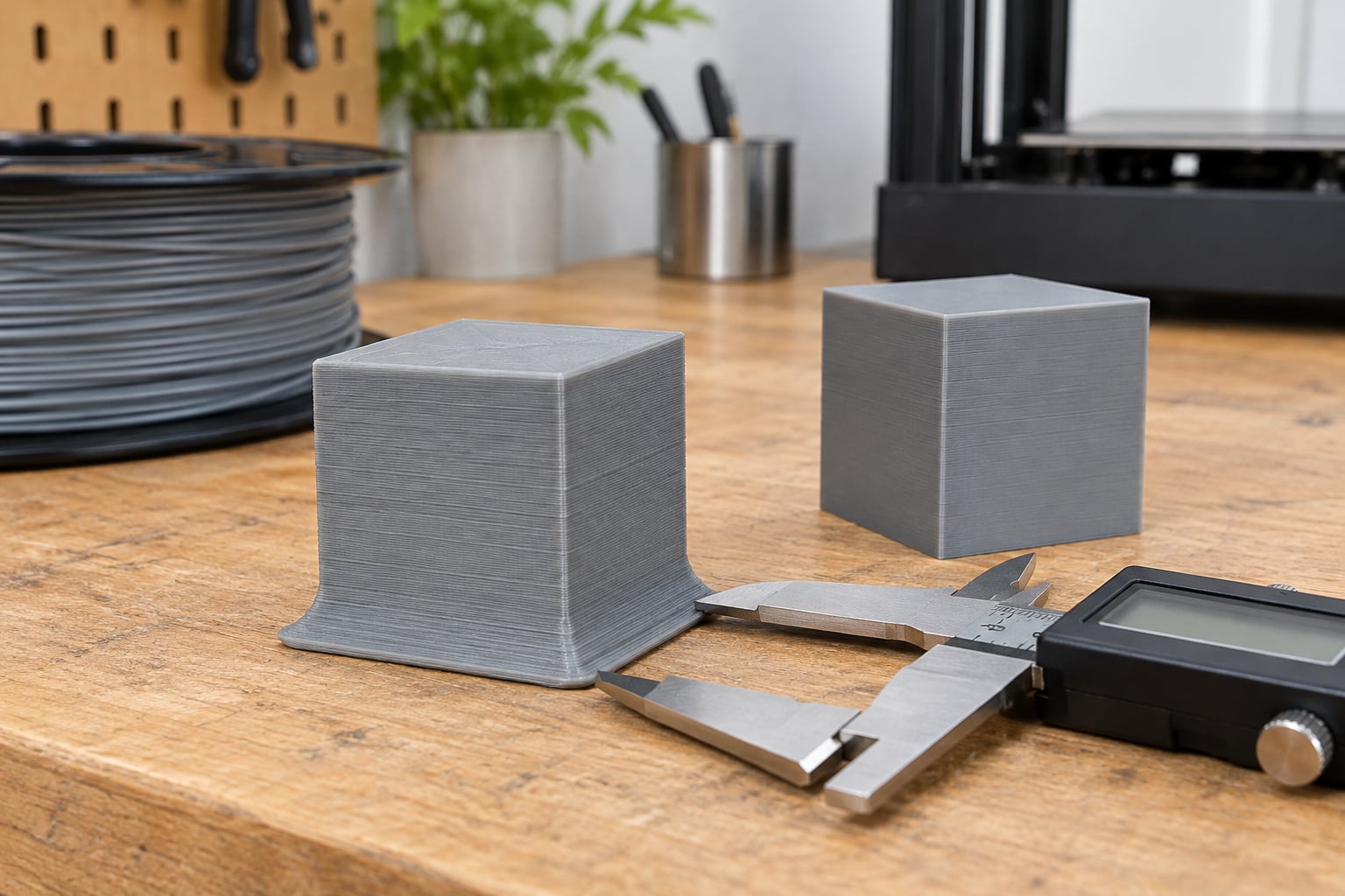
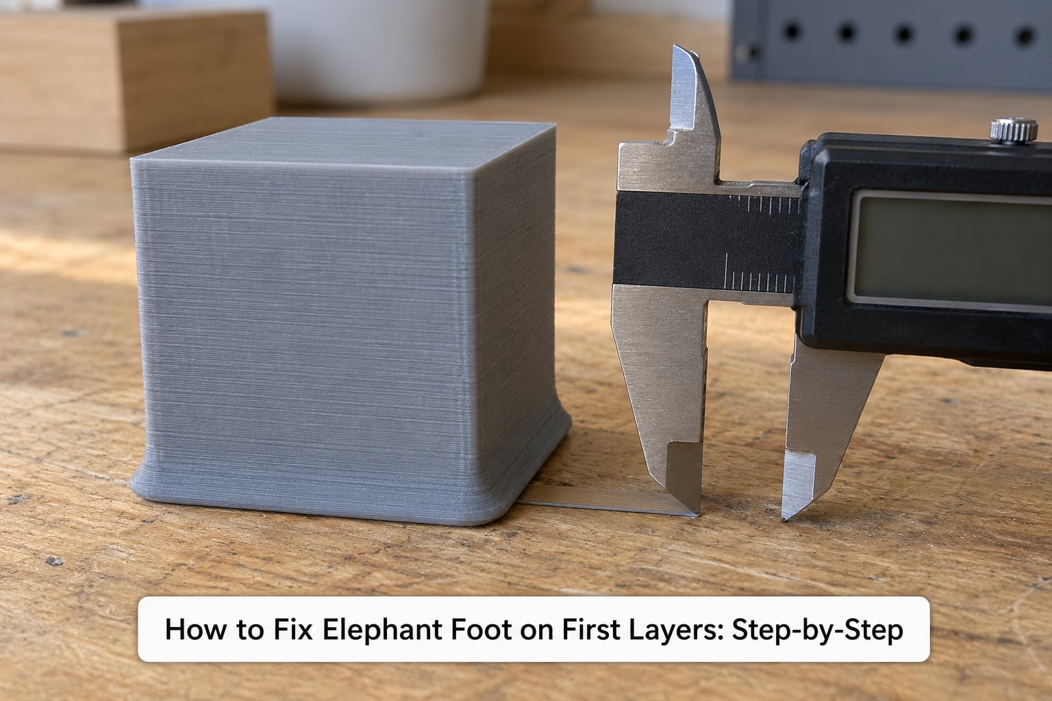
Elephant foot is the soft lip that squashes out around the base of a part when the nozzle presses too hard on a warm first layer. To fix elephant foot on first layers, work in order: clean the plate, confirm the bed is level, raise the Z-offset by 0.05 mm at a time, then drop nozzle temperature 5 to 10 degrees C and trim first-layer flow. Most prints are clean after those four moves, and it takes about 20 minutes per test.
I’ve chased this defect on enough printers to know the frustrating part: it usually is not one setting. It is a hot bed, a nozzle sitting a hair too low, and a part heavy enough to press its own base outward. The good news is that each of those has a single, testable fix.
Before you touch any settings, understand what you are looking at. Elephant foot costs you dimensional accuracy, not strength. A press-fit designed with 0.15 mm of clearance will no longer slide together, a part meant to drop into a frame gets 0.2 mm wider at the base than designed, and any visible edge on a display model loses its crisp line. If your parts are decorative and fit nowhere, ignore it. If they fit into something, fix it properly.
Table of Contents
- What You Need
- How to Fix Elephant Foot on First Layers: Step-by-Step
- 1. Inspect the First-Layer Problem
- 2. Clean and Recheck the Build Plate
- 3. Correct the First-Layer Z-Offset
- 4. Adjust First-Layer Slicer Settings
- 5. Check Temperature and Material Flow
- 6. Test, Compare, and Fine-Tune
- Common Mistakes
- Frequently Asked Questions
- Does elephant foot mean my first layer is not sticking to the bed?
- What is the best slicer setting for fixing elephant foot?
- Should I reduce first-layer adhesion to stop elephant foot?
- Why does elephant foot appear mostly around the corners?
- Will changing the first-layer Z-offset fix the whole print?
- Conclusion
What You Need
You do not need anything exotic. Most of this is done with software you already have open, plus one cheap tool that tells you whether a fix actually worked.
- Access to your printer’s controls — Z-offset and mesh leveling live in the printer menu on most machines, not just the slicer.
- Your slicer — PrusaSlicer, Cura, OrcaSlicer, and Bambu Studio all carry a compensation setting under a different name and, in two cases, an opposite sign.
- Digital calipers — the cheapest useful tool in this whole process, and the only way to measure a fix rather than eyeball it.
- A clean build plate — glass, textured PEI, or smooth PEI. If yours is scratched or warped, no setting corrects it.
- A known-good filament — a fresh spool of the same material, so you are not also debugging filament diameter.
- A 20 mm calibration cube or an equivalent single-wall test block with a flat bottom.
Clean a lint-free cloth or a paper towel, plus isopropyl alcohol for non-PEI plates. Isopropyl alcohol is safe on textured PEI and glass, but skip it on smooth PEI sheets — the coating can go permanently cloudy.
How to Fix Elephant Foot on First Layers: Step-by-Step
The order below matters. Each step assumes the previous one is already correct, so skipping ahead is how people end up compensating in the slicer for a mechanical problem and wondering why nothing changes.
1. Inspect the First-Layer Problem
Elephant foot shows up as a lip that is widest at the very bottom edge and narrows within a few layers, usually 0.1 to 0.3 mm. Photograph the base edge from the side, not the top, so you can see the taper clearly.
Several other defects get mistaken for it, and each has a different fix:
| Symptom | Where it appears | Likely cause |
|---|---|---|
| Base wider than mid-height, tapering within 1 to 3 layers | All around the perimeter | Elephant foot: nozzle too low or bed too hot |
| Base wider than mid-height, same width for 4 to 5 layers | All around the perimeter | Multi-layer flare, common on ASA and nylon, usually a nozzle temperature problem |
| Corners bulge, straight walls look fine | Corners only | Corner bulge from over-extrusion, not elephant foot |
| Corners lifted, edges flat | Corners only | Warping or a failed bed-level check |
| Gaps between lines, part pops off when touched | Whole first layer | Under-extrusion or no adhesion, not a dimensional defect at all |
| Even horizontal ridges partway up the wall | Mid and upper layers | Z-banding, unrelated to the first layer |
To separate elephant foot from over-extrusion, measure the part at the base and again at mid-height. If the mid-height walls are also fat, your flow is too high everywhere and the first layer is not your problem. If the walls match the model and only the base flares, it is elephant foot.
2. Clean and Recheck the Build Plate
Dust, fingerprints, and cured filament residue change the effective Z-gap more than most people expect. Wipe glass or textured PEI with isopropyl alcohol and a lint-free cloth, let it dry fully, and check for grit under the nozzle with a flashlight at a low angle.
On smooth PEI, use warm water and a mild dish soap instead, and never use a scraper or anything abrasive. A scratched or pocked surface gives you the lip plus a weak bond, and no offset change fixes a damaged plate.
Then re-run your printer’s leveling routine. On a manual machine, do the paper test: heat the bed and nozzle, run the home position, slide a sheet of paper under the nozzle, and adjust until it drags with light resistance. Loosen the paper a touch further than feels right — snug feels too tight once the plate heats up.
Automatic bed leveling handles mesh height, not Z-offset. Experienced makers on the forums consistently report that a leveled printer with a wrong Z-offset still prints a squished base, so treat the two as separate jobs. If your printer supports mesh leveling, save the mesh, then set the Z-offset by hand on top of it.
3. Correct the First-Layer Z-Offset
This is the highest-value change in the whole process. Raise the nozzle by 0.05 mm at a time — find it in your printer’s control menu (often under Calibration, Z-Offset, or Bed Leveling) or use your slicer’s first-layer calibration routine in PrusaSlicer, Cura, OrcaSlicer, or Bambu Studio.
Roughly a quarter of a millimetre of extra clearance is often enough. Go too far and you trade a lip for a part that will not stick at all, so print a small single-wall test after each change rather than committing a six-hour print.
The paper test sets proximity at room temperature. Metal expands when hot, and the gap closes as the bed reaches temperature, so do the final confirmation on a real print, not on paper.
4. Adjust First-Layer Slicer Settings
Once the gap is right, trim what gets squeezed. Useful first-layer changes, in the order I make them:
- Flow or extrusion multiplier: 95 to 100% for the first layer only, when adhesion stays strong without setting a separate value.
- First-layer line width: 100 to 110% of nozzle diameter — wider lines spread the same volume over more area, which reduces per-mm compression.
- First-layer speed: 20 to 30 mm/s, even if the rest of the print runs at 150. More time under the nozzle means better bonding without extra pressure.
- Elephant foot compensation — shrink or expand the first layer by a fraction of a millimetre. This is the last fix, not the first.
The setting name and the sign differ by slicer, and copying a number from one to another is the single most common mistake here:
| Slicer | Menu path | Sign | Starting value for a 0.4 mm nozzle |
|---|---|---|---|
| PrusaSlicer | Print settings > Advanced > Elephant foot compensation (needs Advanced or Expert mode) | Positive shrinks the layer | 0.2 mm |
| Cura | Settings > Printer > Manage Profiles > Profile > Advanced > Initial Layer Horizontal Expansion | Negative shrinks the layer | -0.2 mm |
| OrcaSlicer | Filament settings > Advanced, or Project > Printer Settings, elephant foot compensation field | Negative shrinks the layer | -0.2 mm |
| Bambu Studio | Filament settings (custom filament) > Advanced, elephant foot compensation field | Negative shrinks the layer | -0.2 mm |
PrusaSlicer’s value goes up to remove material; the other three need a negative number for the same result. Shared Bambu and Prusa profiles usually sit around 0.15 to 0.2 mm equivalent.
Stay well below half your first-layer extrusion width. There is no hard software maximum, but a value that large often detaches the brim or skirt from the part, and the preview gap that creates is a rendering artifact rather than a real gap.
5. Check Temperature and Material Flow
This is where the fix usually hides when offsets have already been adjusted. Experienced users on r/3Dprinting and r/FixMyPrint report that a nozzle running 5 to 10 degrees C too hot causes large flares that compensation barely touches, because the base stays above its glass transition temperature long enough to creep outward under the weight of the layers above it.
Drop nozzle temperature by 5 degrees C, print a test cube, then drop another 5 if the lip persists. Then stage the bed: run the first layer 5 to 10 degrees C hotter than the rest of the print for adhesion, then let the slicer drop it once the base is set.
Approximate starting points by material, with a 0.4 mm nozzle:
| Material | Nozzle | Bed, first layer | Bed, after layer 1 | Part cooling |
|---|---|---|---|---|
| PLA | 200 to 215 | 55 to 60 | 50 to 55 | 50% or more from layer 2 |
| PETG | 230 to 245 | 70 to 80 | 65 to 75 | 25 to 30% from layer 2 |
| ABS / ASA | 240 to 260 | 95 to 105 | 90 to 100 | Low, and a closed chamber helps |
| TPU | 220 to 235 | 40 to 50 | 40 to 50 | 50% from layer 2 |
| Nylon / PA | 250 to 270 | 70 to 80 | 70 to 80 | Low; dry filament first |
Flow problems hide here too. Measure your filament with calipers before blaming the slicer: anything outside 1.75 mm plus or minus 0.03 mm changes how much plastic actually reaches the plate. If the walls are correct and only the base is fat, diameter is not your culprit — heat and gap are.
6. Test, Compare, and Fine-Tune
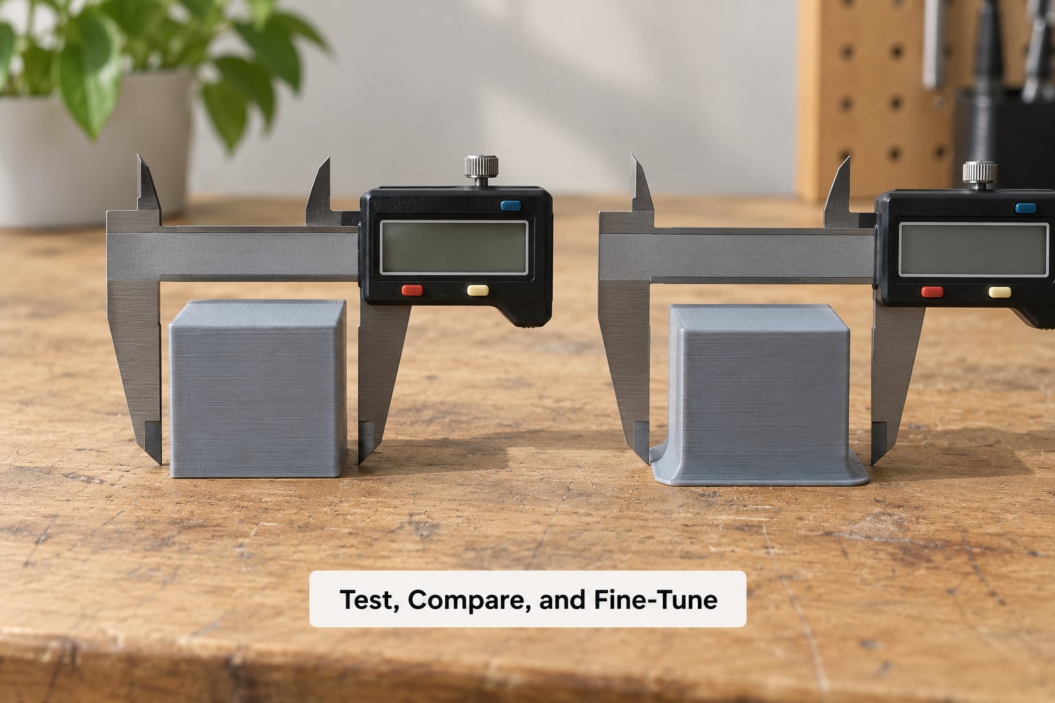
Use a repeatable measurement instead of a photo comparison. Print a 20 mm calibration cube, let it cool fully, and measure the base in two places with calipers — once across a flat edge, once across a corner, and again at mid-height on the same axis.
Write down three numbers: base width, mid-height width, and the difference. The difference is your elephant foot value. Change one variable per print and re-measure the same way, so you know which change moved the number.
Once the base matches the walls within your tolerance, lock the values in as your baseline profile and stop touching them. If you still have a visible flare after all of this and the part does not need to fit anywhere, a 0.2 to 0.4 mm chamfer at the base in your CAD software is a permanent design-side fix, and it costs you nothing at print time.
Common Mistakes
Lowering Z-offset until the nozzle nearly touches the plate. You will feel a satisfying drag and get a part that sticks to the plate like glue, then detaches halfway up. Raise it in 0.05 mm steps and stop at the first clean test.
Thinning the first layer to fix the flare. A squashed first layer is supposed to be a little wider than normal. Squeezing it harder makes the lip bigger, not smaller. Reduce flow or widen lines instead of squeezing the gap.
Over-tightening the bed springs. Cranking every corner to maximum leaves you with a plate that is level at four points and tilted everywhere else. Tighten evenly and let a thermal expansion cycle confirm it.
Changing six settings in one test print. If the result is good you will not know why, and if it is bad you have to start over. One variable, one cube, one caliper reading.
Treating a detachment as a dimensional problem. If the first layer is sticking well and the base is just wide, you have elephant foot. If corners are lifting off the plate, that is warping or leveling, and no slicer setting fixes it.
Expecting compensation to work on a model that already has a chamfer. Users on the Prusa knowledge base threads report hours lost to this: when the STL already carries a base chamfer, compensation shrinks a layer that is no longer the widest part of the model, so setting it from 0 to 0.2 mm changes almost nothing visible.
Raising compensation until the brim detaches. Shrink the layer a little, check the preview, and back off if the skirt or brim separates from the outline. In-place brims defeat compensation entirely, since the brim is printed at the original size.
One practical tip: if the flare appeared suddenly with no printer change, test a fresh spool before adjusting anything. Changing filament brand alters diameter tolerance, colourants, and how the plastic softens against a PEI surface, and that alone can move the lip noticeably.
Frequently Asked Questions
Does elephant foot mean my first layer is not sticking to the bed?
No. Elephant foot is the opposite problem: the layer is sticking so firmly and getting pressed so thin that plastic squeezes out sideways. A first layer that is not sticking shows gaps between lines, visible plate texture, or the part peeling off a corner when you touch it. If your part is stuck down but measures wider at the base than at mid-height, you have elephant foot and your adhesion is fine.
What is the best slicer setting for fixing elephant foot?
There is no single best setting, because the cause is usually mechanical or thermal. Raise your Z-offset first, since a nozzle sitting too low is the most common trigger. Then trim first-layer flow to 95 to 100 percent and slow the first layer to 20 to 30 mm/s. Slicer compensation of about 0.2 mm for a 0.4 mm nozzle is the finishing touch once the hardware side is right.
Should I reduce first-layer adhesion to stop elephant foot?
No, keep adhesion strong. Elephant foot comes from pressure and heat, not from a layer that grips too tightly. Reducing adhesion makes the part more likely to lift or shift mid-print and can cut the print short. Give the layer enough flow to stay bonded and instead widen the lines slightly or lower the nozzle temperature, which reduces compression without weakening the bond.
Why does elephant foot appear mostly around the corners?
Corners carry the most material per square millimetre, because the infill and perimeter loops overlap there. That extra volume plus the corner geometry pushes more plastic outward at the same gap, so corners flare first and hardest. If only the corners are affected while straight walls measure correctly, you are likely looking at corner bulge from over-extrusion rather than elephant foot, and the fix is to check flow before offsets.
Will changing the first-layer Z-offset fix the whole print?
It fixes the first-layer component, which is usually the majority of the flare. On stiff materials like ASA and nylon the soft zone can span four or five layers, and a Z-offset change alone will not reach them. Those cases need a nozzle temperature reduction of 5 to 10 degrees C, or a designed-in base chamfer. Measure the base against mid-height after the change to confirm what is left.
Conclusion
Start with the boring parts, because they fix most cases. Clean the plate, run your leveling routine again, and set the Z-offset by hand a little higher than you think it needs to be. Then make one small change to first-layer flow or drop the nozzle 5 degrees C, print a 20 mm cube, and measure the base against mid-height with calipers. If a lip still shows up after 2026 and a profile is finally holding steady, reach for compensation in your slicer.