How to tighten belts on a Cartesian 3D printer comes down to one movement: loosen the fastener on the axis tensioner, pull the moving end until the belt deflects about 1-2 mm at mid-span, then snug the fastener back down. On an Ender 3, Prusa MINI or Anycubic Kobra the whole job takes 20 to 30 minutes, needs nothing more exotic than a hex key, and only goes wrong if you tighten until the motor strains.
The reason it matters is that belt tension sets the mechanical baseline for everything downstream. Too loose and you get backlash, ringing and layer shifts; too tight and the motor runs hot and the V-wheels wear out. Tension also shifts resonance, so any firmware tuning you did before a tension change has to be redone afterwards.
Table of Contents
- What You Need
- Step-by-Step: How to Tighten Belts on a Cartesian 3D Printer
- Step 1: Identify the Belt System and Adjustment Points
- Step 2: Check the Current Belt Tension
- Step 3: Loosen the Tensioning Fastener
- Step 4: Tighten the Belt Until the Play Is Removed
- Step 5: Recheck Alignment and Test the Printer
- Common Mistakes
- Frequently Asked Questions
- How much tension should a 3D printer belt have?
- Can you adjust the belt tension if my printer has no tensioner?
- How do I tell if my 3D printer belts are too tight?
- Which way do I turn the tension knob to tighten the belt?
- Why does my belt go slack in one part of the travel and tight in another?
- How often should I re-check belt tension, and when should I replace the belt?
- Conclusion: What to Do First
What You Need
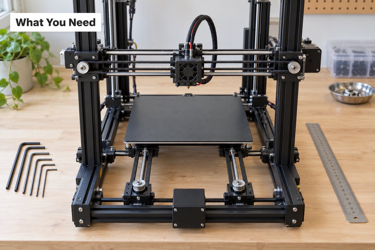
Start with the manual for your specific model. Tensioner layouts vary wildly between a Prusa MINI and an Ender 3, and the manual tells you which screw or knob is the tensioner rather than a mount.
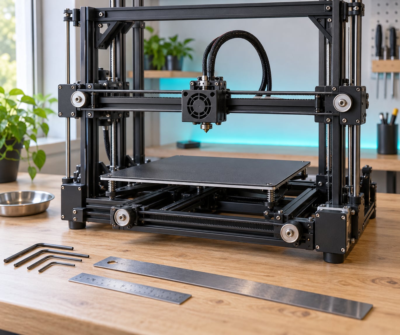
- Hex keys — 2 mm and 3 mm cover most Prusa-style and Creality-style hardware. A 4 mm is occasionally used on a bed-slinger motor plate.
- A straightedge or steel rule — lets you check that the belt span running to the carriage sits parallel to the linear rail.
- A marker — mark the tensioner position before you loosen anything, so you can return to it if the belt needs to go back.
- A phone with a tuner app — optional, but it turns the pluck test from guesswork into a number.
- A small spring scale — also optional, useful if you prefer force over deflection.
A multimeter is not part of this job. Tension is mechanical, and the useful measurements here are millimetres of deflection and hertz of pitch, not volts.
Step-by-Step: How to Tighten Belts on a Cartesian 3D Printer
Unplug the printer before you touch anything. Steppers hold position when powered, and a hand near a pulley that moves without warning is how people pinch a finger. Work one axis at a time, and finish with a test move before you start the next.
Step 1: Identify the Belt System and Adjustment Points
On a bed-slinger the X belt drives the gantry that carries the toolhead, and the Y belt pushes the bed back and forth. Both are 2 mm-pitch GT2 timing belts in almost every case, and both usually run through one moving idler or a sliding motor mount. Find each idler, mark its position with the marker, and note which way the belt has to travel to take up slack.
The fastener you want is the one that moves the idler away from its pulley. Everything else on that assembly is a mount and stays put.
| Tensioner type | Tool | How to tighten |
|---|---|---|
| Thumb-turn knob or eccentric | None | Turn the knob until deflection hits 1-2 mm. Quarter turns, re-testing between each. |
| Sliding bracket held by two hex screws | 2 mm or 3 mm hex | Loosen both screws, push the bracket until the slack is gone, then snug both screws evenly. |
| Slotted motor mount | 2.5 mm or 3 mm hex | Loosen the mount screws, slide the motor away from the idler to tension, then tighten the mount screws. |
| Idler on its own post, no adjustment | Depends on the frame | Fit a printable tensioner block, or slot the mount plate so the motor can be pulled and bolted. |
A sliding motor mount is the setup that usually holds tension best on a long-print machine. A spring tensioner does take up slack, but it introduces its own backlash, which defeats the point.
Step 2: Check the Current Belt Tension
Push the middle of each free belt span down with a fingertip and watch the deflection. Correct 3D printer belt tension gives you 1-2 mm at the centre of the span — firm enough to pluck, still flexible enough to pinch flat with a fingernail. Pluck it and a phone tuner app should read roughly 60-90 Hz. Bass and clear is the target; a thin ping means it is too tight, a dead thud means too loose.
Push the carriage by hand with the power off. It should glide the length of the travel with no notching, no dead zones, and no binding at either end. A carriage that glides freely at one end and catches at the other is a geometry problem, not a tension problem.
| Symptom | Too loose | Too tight | Test that confirms it |
|---|---|---|---|
| Ghosting or ringing on walls | Yes | Yes, at high speed | Pluck test reading, plus a slow print of a straight wall |
| Layer shifts on fast moves | Yes | No | Hand-glide test showing backlash at direction change |
| Belt slap noise | Yes | No | Listen while the axis travels |
| Axis binds at one end of travel | No | Yes | Hand-glide from end to end, and the straightedge check |
| Motor running hot to the touch | No | Yes | Touch the motor body after a long print |
| Visible V-wheel wear or frayed belt edge | No | Yes | Visual inspection of the belt edge and the wheel bore |
Step 3: Loosen the Tensioning Fastener
Support the frame with one hand so the gantry or bed does not drop when the fastener releases. Loosen only the tensioning screw or knob, a quarter to half turn at first — most brackets hold position by friction and will not fall the moment the screw is out.
Keep the pulley from twisting as you work, and keep the belt teeth seated in the groove. A belt that jumps a tooth while you are adjusting it will feel tight when it is not, which is the most common way to end this job chasing the wrong problem.
Step 4: Tighten the Belt Until the Play Is Removed
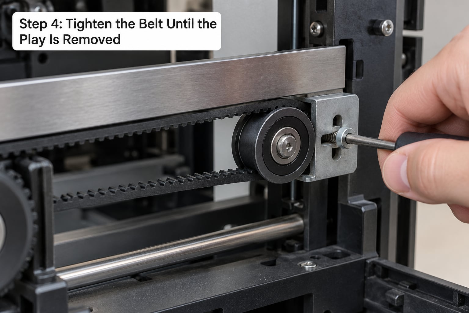
Move the idler or motor a small amount at a time and re-test deflection before each turn. For a knob, that means quarter turns. For a sliding bracket, a few millimetres of travel. Keep the belt aligned with the rail it drives while you work — pushing sideways to reach the deflection number twists the belt and wears its edge.
Stop at 1-2 mm. Going further buys nothing measurable in print quality and costs you motor bearings, V-wheel life and a lot of noise from the machine.
On a bed-slinger there is one difference worth knowing. The Y axis pushes a heavy heated bed, so its belt carries more static load and usually wants to sit a touch firmer than X. More importantly, tension on Y can vary with bed position if the belt path is twisted, so test the deflection at three points along the travel rather than one. If the numbers differ, the belt path needs correcting, not more tension.
Step 5: Recheck Alignment and Test the Printer
Snug every fastener back up, then press the straightedge against the belt span that is clamped to the moving carriage and against the linear rail it runs alongside. Those two faces should sit flush. Only the span attached to the moving part needs to be parallel to the rails; the return span of the loop does not, and chasing that second span is a common waste of an afternoon.
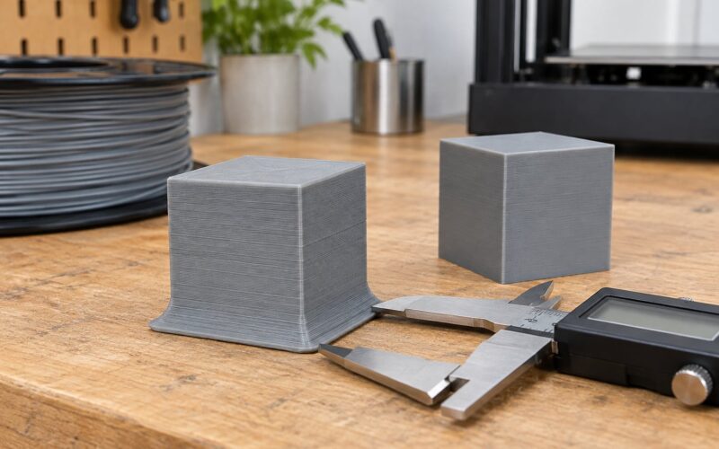
Power the printer on with the motors disabled if your firmware allows it, and move each axis by hand at low speed through a full traverse. It should feel identical at the centre and at both ends. Then print a calibration cube and measure the walls with calipers. Dimensions that changed after a tension adjustment tell you the tension was not the whole story — look next at the wheels and the frame squareness.
If you run Klipper, measure resonance again after any tension change, because the frequency moves when the belt stiffness does. Marlin has no equivalent built-in test, so a printed ringing tower is your practical check.
Common Mistakes
Tightening the wrong fastener. The motor mount screws look identical to the tensioner screw. Mark the tensioner with the marker first, and confirm by loosening it — if the belt does not go slack, it is a mount, not a tensioner.
Over-tightening. Cranking the knob until the motor strains is the single most damaging habit here. It wears V-wheels and motor bearings, heats the motors under load, and can make an axis bind at one end of travel. The deflection test stops you well before the damage starts.
Ignoring belt path geometry. If the carriage-clamped span is not parallel to the rails, tension varies with position and no amount of adjustment fixes it. Position-dependent step loss on one axis is nearly always a pulley or gantry squareness issue rather than a tension issue, and it will keep coming back until the pulleys are repositioned. Run the straightedge check before the deflection test when the problem moves with the axis position.
Adjusting two axes at once. You lose the ability to attribute the change. Finish X, run the test, then move to Y.
Leaving a marking undone. Sliding brackets drift as the frame flexes, and without a reference mark you have no way back. One pen line next to the bracket saves a rebuild.
Fighting a damaged belt. Frayed edge fibres, a missing tooth or a shiny glazed surface will not tension properly no matter what the gauge says. Replace it, then tension the fresh belt from scratch.
One more thing: never oil the belt. Oil on a GT2 belt collects at the teeth, throws a fine dust onto the pulleys, and makes the belt slip when you least want it to.
Frequently Asked Questions
How much tension should a 3D printer belt have?
Push the middle of each free belt span down with a fingertip. Correct 3D printer belt tension deflects about 1-2 mm at mid-span, still allows a fingernail to pinch the belt flat, and plucks a low clear note around 60-90 Hz on a phone tuner app. Anything that feels slack, thuds when plucked, or reads as a thin ping is out of range in one direction or the other.
Can you adjust the belt tension if my printer has no tensioner?
Yes, and most converted or DIY frames can be made serviceable in one of three ways. Slot the motor mount plate so the motor can be pulled away from the idler and bolted down, fit a sliding bracket in place of the fixed idler post, or add a printable tensioner block. Avoid spring or clothespin tensioners: they absorb slack but add backlash, which is the very thing you are trying to remove.
How do I tell if my 3D printer belts are too tight?
Two checks catch it. Pluck the belt and listen: a thin high ping means over-tensioned, a low clear note is correct. Then hand-glide the axis with the power off and listen for binding at the end of travel, which over-tension creates. Hot motor housings after a long print and shiny or frayed belt edges are the slower signs, and both mean damage is already under way.
Which way do I turn the tension knob to tighten the belt?
It depends on how the pulley is mounted, so do not guess. Mark the idler position, note which way the belt runs, and turn the knob a quarter turn in either direction. If deflection does not change, you turned the wrong way or you are on the wrong fastener. Working in quarter turns and re-measuring deflection each time removes the guesswork entirely.
Why does my belt go slack in one part of the travel and tight in another?
That pattern almost always means the belt path is twisted, not that the tension is wrong. The span clamped to the moving carriage must run parallel to the linear rail beside it. If it does not, tension rises and falls as the carriage moves. Press a straightedge against that span and the rail: if they are not flush, reposition the pulleys before touching the tensioner again.
How often should I re-check belt tension, and when should I replace the belt?
Re-check every three to five prints and always after any belt change, pulley swap or firmware stepper tuning. Belts stretch and idler bushings wear slowly, so tension drifts without anything visibly breaking. Replace the belt when you see frayed edge fibres, a cracked or missing tooth, a glazed shiny surface, or visible grooves worn into the pulley teeth.
Conclusion: What to Do First
Start with the axis giving you the most visible problem, and only that one. Mark the tensioner, loosen its fastener a quarter turn, pull until the belt deflects 1-2 mm at mid-span, then snug the fastener back and confirm the carriage glides freely at low speed with the motors disabled.
If it glides freely end to end and the symptom is still there, the answer is in belt path geometry rather than tension. Move to the next axis only once the first one is verified with a calibration cube, and re-measure resonance afterwards if you use input shaping.