A snap fit is a flexible hook on one part and a matching undercut on the other, so the hook bends during assembly and springs back to lock the two pieces together. Designing snap fit joints for 3D printing is mostly two decisions: give the arm enough length and width to deflect safely, and orient the part so the bend runs along the layer lines. An hour of coupon printing settles both before you cut a full enclosure.
A printable snap is a spring, and springs fail in predictable ways. Most broken arms trace back to a stiff short hook printed standing on end, which forces a brittle PLA or a low layer count to do work the geometry should have done. Fix the proportions and the print orientation first, and the tolerance numbers stop being guesswork.
Table of Contents
- What You Need
- Step-by-Step: Designing a Printable Snap Fit
- 1. Define the joint’s function and insertion direction
- 2. Choose a snap-fit geometry that suits the printer
- 3. Set the interference and clearance dimensions
- 4. Model the flexing arm and root
- 5. Add a lead-in and avoid sharp retention features
- 6. Check print orientation, supports, and surface quality
- 7. Print a calibrated test coupon
- 8. Refine the final CAD model
- Common Mistakes and How to Fix Them
- Frequently Asked Questions
- What are the design guidelines for snap-fit joints?
- What clearance should I use for a snap fit on an FDM printer?
- Can I use PLA for snap fit joints?
- What is the best print orientation for a snap fit arm?
- Why does my 3D printed snap fit keep breaking or not returning to shape?
- What are the downsides of snap-fit joints?
- Conclusion
What You Need
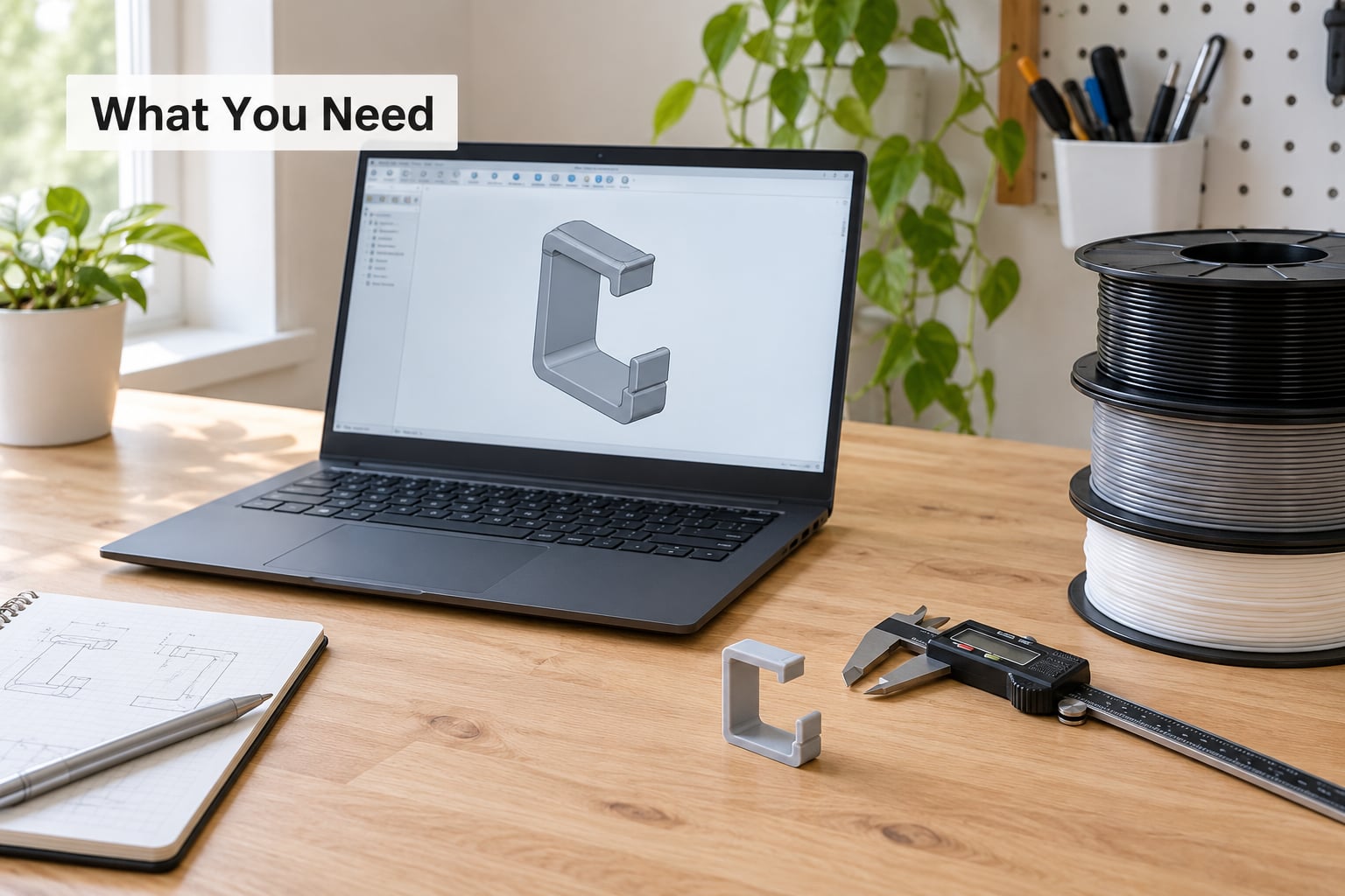
A CAD package with a fillet and chamfer tool. Fusion 360, SolidWorks, Onshape and FreeCAD all do this job, and every dimension below is tool-agnostic. If you are still choosing, anything with a proper mirror feature saves time because a snap pair is almost always two mirrored halves.
Digital calipers, ideally with 0.01mm resolution. You will measure your own printed coupon to find your machine’s real clearance, which matters more than any published number.
A printer you can run a small part on tonight. A 100 percent-scale coupon takes well under an hour on any machine, so there is no excuse for designing the whole assembly blind.
At least two filaments. PLA and PETG make the material point obvious in one test, and a tough filament like PA or PP is worth having if the part will be cycled repeatedly.
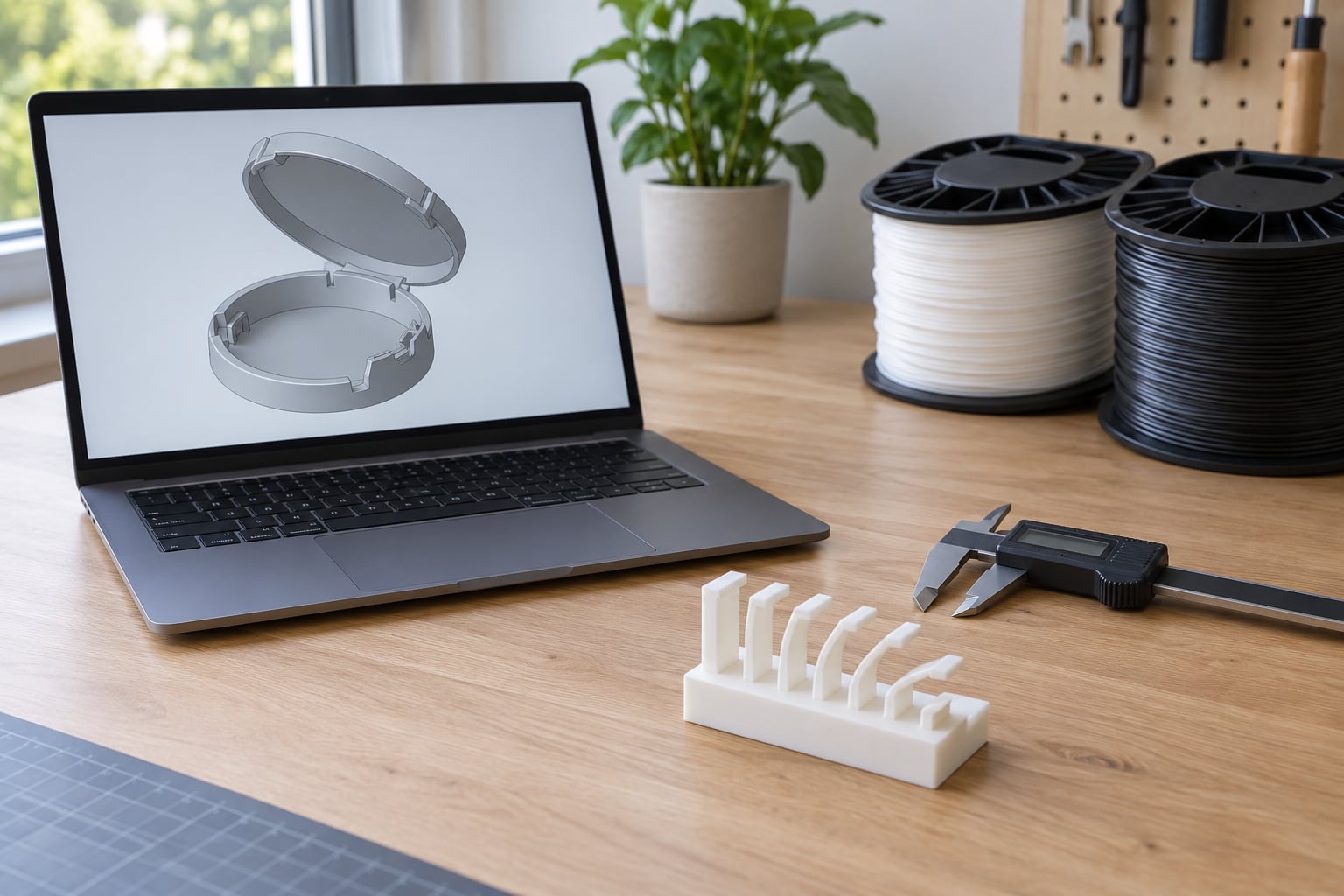
A small test coupon design: a flat plate with four or five cantilever arms, each with a different interference value or arm thickness. This single plate answers the tolerance and stiffness questions together.
Step-by-Step: Designing a Printable Snap Fit
1. Define the joint’s function and insertion direction
Decide two things before you sketch anything: does the joint have to be removable, and how much force is reasonable to push it together with. A battery door that gets opened twice a week can use a deep undercut. A case that gets snapped shut once and never reopened can use a shallow one and a generous lead-in, because assembly force is not a concern.
Insertion direction decides geometry. A straight push along one axis is the easy case. A snap that must engage on two perpendicular features at once is asking for binding, so add locating lugs or a lead-in chamfer that self-centres the two parts before the hook finds its undercut.
Note where the part has to sit in the printer. If the flexing arm has to be printed flat on the bed to survive, and the bed is 180mm across, that may rule out the cantilever you wanted. Geometry follows the printer, not the other way round.
2. Choose a snap-fit geometry that suits the printer
| Geometry | How it works | Where it works well | Watch out for |
|---|---|---|---|
| Cantilever | One flexible arm with a hook that releases past a ledge | Enclosure lids, battery doors, latches on FDM | Needs the arm to bend along the layers |
| U-shaped cantilever | Two arms sharing a root, often a leaf-spring shape | Wide panels where you want a top surface left flat | More print time, harder to keep the two arms matched |
| Torsional | A flexible post twists as a cap snaps over it | Round caps, pen and bottle closures, panel latches | Tolerance-sensitive, weak with low layer adhesion |
| Annular | A continuous ring groove with an undercut lip | Bottle caps, watertight circular seals | Hoop strain around the whole circumference |
| Low-profile button | A short pillar with a snap bead, usually on a printed-in hole | Panels where there is no room for an arm | Brittle on PLA, tiny tolerances |
Cantilever is the default for a first design and the type most guides measure. The rest solve space problems the cantilever cannot: torsional fits when the closure is round, annular when you need a continuous seal line.
3. Set the interference and clearance dimensions
Clearance here means the free gap between the flexing arm and the surface it rubs past, measured per side. Interference is the small amount of overlap you deliberately build into the hook so it has something to press against. There is no universal number, because each process and each machine lands differently.
| Process | Per-side clearance | Why |
|---|---|---|
| FDM, 0.4mm nozzle, tuned | 0.3-0.4mm | Elephant foot and first-layer squish eat into the gap |
| FDM, 0.6mm nozzle or large panels | 0.4-0.6mm | Wider extrusion and more warp on big surfaces |
| SLA resin | 0.15-0.25mm | Near-isotropic and accurate, but resin shrinks as it cures |
| SLS or MJF nylon | 0.2-0.3mm | Grainy surface adds friction, so lean to the tight end |
| Printed part against metal | 0.5-0.8mm | Metal never moves, so extra room costs nothing |
Working starting points for a cantilever arm: 0.8-2mm thick, at least 5mm wide, an 8-20mm free length, a root fillet radius of half the base thickness, a 30-45 degree lead-in chamfer and a 60-90 degree retention angle on the face that holds the part closed.
Then build a coupon. Model one arm five times with clearances of 0.2, 0.3, 0.4, 0.5 and 0.6mm, print it, and write down which one inserts with a thumb, which needs two hands, and which does nothing. That is your machine’s number, and it beats any table you find online.
4. Model the flexing arm and root
Widen the arm rather than thickening it. Stiffness in bending scales with the third power of thickness but only with the first power of width, so doubling thickness multiplies the force you need by about eight while doubling width only doubles it. Makers on the forums reach the same conclusion the long way: a longer, thinner, wider arm solves a stiff snap better than a thick one.
Taper the arm. A constant-thickness beam stores the most energy at its root, so it is the first place to tear. Reducing thickness toward the tip by a millimeter or so spreads the strain along the length and buys a large jump in cycle life for free.
Fillet the root generously, at least half the base thickness. A sharp internal corner is a stress riser and a crack starter, and thick printed corners are where fatigue begins.
If you want to do the quick check, the second moment of area for a rectangular arm is I = b x h cubed, divided by twelve, where b is width and h is thickness. Take a 10mm wide, 1.5mm thick PETG arm 15mm long, a modulus near 2000 N per square millimetre, and 20N at the tip. That gives a second moment of area of about 2.8 cubic millimetres to the fourth, roughly 4mm of tip deflection, and about 4 percent surface flex strain. That number is the whole story in one line: PLA often cracks before it reaches 4 percent, PETG bends there repeatedly without complaint.
5. Add a lead-in and avoid sharp retention features
The lead-in chamfer at 30-45 degrees decides whether the part goes in smoothly or gets forced. It also stops the hook from shearing when the two parts are not perfectly aligned, which is the usual reason a first attempt chips instead of snapping.
Round the leading corner of the hook. A sharp point drags across the mating surface and acts as a cutter, and a sharp trailing edge is a fatigue crack waiting for cycle number 40.
Keep the retention angle between 60 and 90 degrees. That is enough hold to keep a lid shut, shallow enough that a fingernail can release it. If the lid cannot be opened after it closes, reduce the retention angle before you increase the clearance, and if it falls open on its own, the angle is the first thing to steepen.
For parts that get opened constantly, add finger ramps or a small tab so the joint is released deliberately rather than by levering against a hook.
6. Check print orientation, supports, and surface quality
Bend along the layer lines, never across them. A printed arm is far stronger in the plane of the layers than through them, and vendor testing has put the loss in Z at roughly half the elongation at break. Printing the arm flat on the bed, or on its side with the bend running parallel to the layers, is the single most-cited fix in maker communities for arms that snap on first flex.
Keep supports off the arm. A support raft under a cantilever leaves a rough patch and a stress riser exactly where the arm flexes, so use a slicer support blocker, paint the arm red in the slicer, or orient the part so the arm hangs free. Slicers also have an option to treat small regions as solid without adding infill lines, which keeps a thin arm from being hollowed out and crushed.
Give the arm solid infill and at least three walls. A low infill pattern inside the arm lets it buckle rather than flex, which reads as a snap that breaks for no visible reason.
Expect surface finish to affect friction. A slightly rough printed surface grips the mating face and helps retention, while PETG stringing and first-layer elephant foot on the inside of the cavity can stop a lid seating at all. Print the cavity walls last, clean any stringing, and check that the seam is not sitting in the rubbing path.
7. Print a calibrated test coupon
The coupon should contain several arm thicknesses or interference values on one plate, printed in the orientation you intend to use. Print it with the same material, layer height and temperatures as the real part, because a coupon in PLA tells you nothing about a part in PETG.
Record four things for each arm: whether it inserts by hand, how it feels coming over the retention face, where it fails if you force it, and whether it returns to shape. Push-pull cycles are worth counting. An arm that survives twenty closures and then cracks has told you to taper it or add a fillet, and it told you early.
Measure the printed cavity with calipers and compare it to the model. If your 0.3mm design printed at 0.1mm of real clearance, every other joint in the assembly is 0.2mm too tight and you can fix the whole design at once.
8. Refine the final CAD model
Apply what the coupon taught you to the real part. If the arm was too stiff, lengthen it or widen it before you thin it further. If the hook chipped, add the lead-in and round the corner. If retention was weak, steepen the retention angle rather than deepening the undercut, which raises insertion force faster than it raises hold.
Add locating lugs and alignment posts so the two parts square up before the snap engages. They share the shear load and stop a misaligned hook from taking the full force on one corner.
Check the walls around the cavity, the thickness under the arm root, and the screw or post bosses nearby, all against your printer’s minimum feature size. A snap arm is rarely the weakest part; it is just the part that gets stressed, so the surrounding wall often fails first.
Common Mistakes and How to Fix Them
| What happened | Likely cause | Fix |
|---|---|---|
| Will not insert at all | Clearance too small for your machine, or elephant foot in the cavity | Add 0.1mm per side and recheck first-layer squish |
| Assembles once, never opens again | Retention angle too steep or interference too high | Reduce retention angle to 60-70 degrees, lower interference |
| Falls open on its own | Undercut too shallow, arm too flexible, no lip on the mating face | Deepen the undercut to at least 1mm and widen the arm |
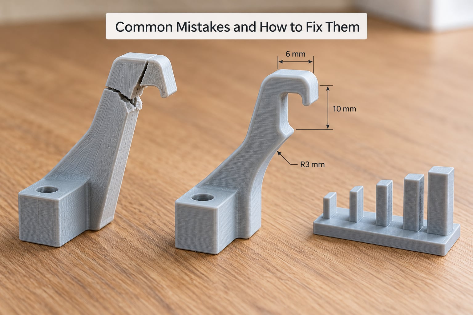
| Arm snaps on first flex | PLA, or bending across layer lines | Switch to PETG and reorient so the bend runs along the layers |
| Cracks at the root after 20-40 cycles | Sharp root corner and constant-thickness arm | Add a fillet of half the base thickness and taper the arm |
| Crushes instead of springing back | Low infill or too few walls inside the arm | Solid infill, three or more walls |
| Stiff even with generous clearance | Arm too short, too thick, or the wrong material | Lengthen and widen the arm, lower thickness to 1-1.5mm |
| Lid will not seat fully | Stringing, seam scar or support scar in the cavity | Clear the cavity, reorient the part away from the seam |
| Looks soldered together | Under-extruded or warped print, clearance never actually achieved | Flow-check, level the bed, re-print the coupon |
| Works in CAD, fails in the hand | Design never checked against a real print tolerance | Print the coupon before finalising the part |
One habit covers most of this list. When a joint feels wrong, measure the printed part before changing the model, because the model is usually right and the machine is off by a few tenths.
Frequently Asked Questions
What are the design guidelines for snap-fit joints?
Give the arm enough length and width to flex, fillet the root, taper the arm, round the hook corner, and add a 30-45 degree lead-in chamfer with a 60-90 degree retention face. Keep the arm at least 5mm wide and 0.8-2mm thick, fillet the root at half the base thickness, and orient the part so the bend runs along the layer lines.
What clearance should I use for a snap fit on an FDM printer?
Start at 0.3-0.4mm per side on a tuned 0.4mm nozzle, and go up to 0.4-0.6mm on a 0.6mm nozzle or a large panel that is prone to warping. Then print a coupon with 0.2, 0.3, 0.4, 0.5 and 0.6mm versions and measure. First-layer squish and calibration move your real clearance more than the process name does.
Can I use PLA for snap fit joints?
Only for a joint that snaps together once and stays closed. PLA has low flex strain and cracks around four percent, so a cantilever arm often breaks on the first bend. PETG is the better beginner choice because it flexes repeatedly without splitting. Nylon and polypropylene last longest but need drying and, for nylon, an enclosure.
What is the best print orientation for a snap fit arm?
Print the arm so it bends along the layer lines, which means flat on the bed or on its side with the bend direction parallel to the layers, not standing on end. A printed part is far weaker across layer lines, and that weakness is why many arms snap on first flex. Keep supports off the arm with a support blocker in the slicer.
Why does my 3D printed snap fit keep breaking or not returning to shape?
Three causes cover most cases. It is bending across layer lines, it has a sharp root corner that acts as a stress riser, or the material is too brittle for the strain involved. Reorient the arm along the layers, add a fillet of half the base thickness, taper the arm, and move to PETG. Low infill inside the arm also lets it crush instead of flexing.
What are the downsides of snap-fit joints?
They are hard to adjust after printing, and a joint that is too tight cannot be rescued without reprinting. Retention can creep or relax over time in a material that is not stiff enough. For parts that must be opened often, carry a load, or come apart under heat, a screw with a heat-set insert is usually the better answer.
Conclusion
Start with a coupon, not the enclosure. Model one flat plate carrying four or five cantilever arms at 0.2 to 0.6mm clearance, print it in PETG in the orientation your real part needs, and record how each one inserts, how it holds, and where it cracks. Put the winning clearance into the model, widen and taper the arm, fillet the root, add the lead-in chamfer, and block the supports off the flexing feature. Designing snap fit joints for 3D printing stops being trial and error once the measurement comes from your own printer.