Most moving joints in a printed assembly want somewhere between 0.2 mm and 0.5 mm of gap on FDM, and 0.1 mm is often enough in resin. There is no single right number, because the gap that works on a well-tuned printer in PLA will bind on a different one in ABS. The honest way to pick tolerances for 3D printed moving parts is to start from a clearance that matches your function, then prove it with a small printed coupon and a caliper.
The reason generic dimensional tolerances disappoint people is that a tolerance is written per feature, while a printed part moves as a whole. A hole and a shaft on the same part can each sit inside their own tolerance and still jam, because layer lines, shrinkage and a hole that always comes out undersized all push the same direction.
Table of Contents
- What Tolerances Are Right for 3D Printed Moving Parts?
- Tolerance vs. Clearance vs. Fit: What Is the Difference?
- A hole-and-shaft example in real numbers
- Which Clearance Do Common Moving Parts Need?
- How Do Materials and Printing Methods Change the Fit?
- How to Set Tolerances for 3D Printed Moving Parts by Function
- What changes the number from one joint to the next
- How to Account for Shrinkage and Print Orientation
- The horizontal expansion setting that fixes most holes
- How to Test-Fit and Tune an Assembly
- What Measurements and Tools Give the Best Results?
- How to Fix a Too-Tight or Too-Loose Printed Part
- Frequently Asked Questions
- What is a good starting clearance for 3D printed moving parts?
- Should I scale the entire model or change only the moving fit?
- Why does an FDM hole fit differently from the same hole printed in resin?
- Can I ream or drill an FDM part to correct a tight hole?
- How do temperature and material affect tolerances for 3D printed moving parts?
- Conclusion
What Tolerances Are Right for 3D Printed Moving Parts?
Tolerances for 3D printed moving parts depend on printer accuracy, material shrinkage, feature size, what the joint has to do, and how much freedom of movement you want. Functional clearances beat fixed target dimensions, and you should confirm them with calibrated measurements rather than trusting the slicer preview.
Five things move that number, and it is worth knowing which of them you can control:
- Printer class. A well-maintained bed-slinger and a high-speed CoreXY machine with pressure advance and input shaping will not hold the same hole size from one Tuesday to the next.
- Material. PLA and PETG barely move. ABS, ASA and nylon shrink enough to close a tight fit on their own.
- Feature size and orientation. Vertical holes print smaller than horizontal ones. Small holes drift more, because a fixed error is a larger percentage of a 3 mm bore.
- What the joint does. A hinge that swings freely needs more room than a shaft carrying a light load through a bearing.
- Environment. A car dashboard in summer is a different design problem than a mechanism sitting on a desk.
If you take one habit from this guide, make it printing a coupon before the real part. Twenty minutes of test print saves a twenty-hour mistake.
Tolerance vs. Clearance vs. Fit: What Is the Difference?
These three words get used interchangeably, and they are not the same. Getting them straight makes every later number easier to reason about.
Tolerance is the permitted amount of variation on a single dimension. A 5.00 mm shaft specified as 5.00 plus or minus 0.05 mm has a bilateral tolerance; the 0.10 mm band between 4.95 and 5.05 is the tolerance, not the shaft.
Clearance is the actual gap that results when a hole and a shaft are assembled, measured as the difference between them. Hole minus shaft equals clearance. Positive is a clearance fit, zero is line-to-line, negative is an interference fit.
Fit is the condition of the assembled pair, classified three ways:
- Clearance fit — the hole is always larger. Free movement, no force needed.
- Transition fit — sometimes clear, sometimes interfering. The worst option for a prototype, because it is unpredictable.
- Interference fit — the shaft is always larger. Pressed, hammered or thermally assembled. Real, but hard on plastic.
A datum is the feature everything else is measured from, usually a flat face or a shaft axis. It matters in printing because a warped flat surface shifts every hole relative to it, so the two mating parts stop sharing a reference.
A hole-and-shaft example in real numbers
You model a 5 mm shaft and a 5.2 mm hole, a nominal 0.2 mm clearance. On a typical FDM print the hole comes out at 4.95 mm after the STL polygon approximation and the shrink that comes with a vertical bore. Real clearance is 4.95 minus 5.00, which is negative. The joint is an interference fit, and it will not turn.
That single conversion from CAD to plastic is why designers who copy numbers from a spec sheet keep getting stuck parts. Print the pair, measure it, and only then decide what to change.
Which Clearance Do Common Moving Parts Need?
These are starting points for a well-calibrated FDM machine, not engineering guarantees. Treat the left column as design intent and the right column as the number to test first.
| Joint | Design intent | FDM starting clearance | Resin starting clearance |
|---|---|---|---|
| Shaft in a bore (light load) | Free rotation, no rattle | 0.3 – 0.4 mm | 0.10 – 0.15 mm |
| Rotating ring or collar | Even rotation with visible gap | 0.4 – 0.5 mm | 0.15 – 0.25 mm |
| Sliding piece in a guide rail | Slide by hand, no bind | 0.4 – 0.6 mm | 0.15 – 0.25 mm |
| Print-in-place hinge | Repeated flexing, stays intact | 0.4 – 0.6 mm | 0.20 – 0.30 mm |
| Snap fit (cantilever) | Audible click, holds when pulled | 0.3 – 0.4 mm at the root | 0.10 – 0.20 mm |
| Lever arm on a pin | Rocking motion, no side play | 0.2 – 0.3 mm | 0.05 – 0.10 mm |
| Bearing bore (press fit) | Grip by interference, square shoulder | -0.05 to -0.15 mm | -0.02 to -0.05 mm |
| Dovetail or tab joint | Slide together, adjustable | 0.3 – 0.5 mm | 0.15 – 0.20 mm |
Notice how the numbers climb as the required motion gets looser. A press fit is the only entry with a negative value, and it is also the one most often ruined by shrinkage, because a bearing bore depends on plastic gripping the outer race rather than on a gap.
These numbers are the consensus in print-in-place tolerance discussions, and they line up with what people report after months of iterating on FDM mechanisms: 0.2 mm for tight fits, 0.3 to 0.4 mm for loose and sliding joints, and resin users landing happily in the 0.05 to 0.1 mm band.
How Do Materials and Printing Methods Change the Fit?
The process decides how repeatable your hole sizes are. The material then decides how far everything moves after it cools.
| Process | Typical dimensional accuracy | What it does to fits | Finish |
|---|---|---|---|
| FDM | Around plus or minus 0.2 mm | Holes print undersized; layer seams add burrs; elephants foot affects the first layers | Rough, benefits from deburring |
| Resin (SLA/MSLA) | Around plus or minus 0.05 mm | Holes shrink slightly and need a wash and cure cycle; distortion around heavy supports | Smooth, sometimes glassy and brittle |
| SLS / MJF | Around plus or minus 0.15 mm | No support contact, so no support marks; powder gives a soft internal surface that wears in | Grainy, self-supporting |
| Powder metal (DMLS/SLM) | Around plus or minus 0.05 mm | Shrinkage is significant and must be compensated in the slicer; holes print close to nominal | Very fine, needs support removal |
| PolyJet | Around plus or minus 0.1 mm | Accuracy depends heavily on which polymer is used; glossy surfaces are slippery for moving contact | Excellent detail |
| TPU (FDM) | Around plus or minus 0.3 mm | Flexible and squishy, so clearances need more room and shrink noticeably on the bed | Rubbery, no detail |
Material shrinkage is the second half of the problem. Scale your model before printing and a tight fit becomes correct on paper but loose in the hand, while press fits get worse in the opposite direction.
| Material | Shrinkage behaviour | Practical response |
|---|---|---|
| PLA | Very stable, minimal shrink | Design as modelled |
| PETG | Small, predictable shrink | Design as modelled, add a little extra gap for long spans |
| ABS / ASA | Notably larger, temperature dependent | Scale up around 1 to 2 percent, or enlarge holes specifically |
| Nylon (PA) | High moisture absorption, post-print growth | Measure the dry spool, expect change with humidity |
| TPU | Soft, compresses under load | Design for a squeeze fit, not a precision one |
| Resin | Small, cure-related | Fully cure before measuring or testing fit |
One warning about scaling: print a coupon before you apply a global scale factor to a 200-hour model. Scaling everything changes every fit in the assembly at once, including the ones that already worked.
How to Set Tolerances for 3D Printed Moving Parts by Function
Rather than picking a number and hoping, work backwards from what the joint has to survive. Start with the question: how much slop can you live with? A display model rotating next to a camera slider needs precision. A shop door hinge modelled in plastic needs almost none.
Then adjust the base clearance for the conditions:
- Load. More force on the joint means the material flexes more under use. Add clearance so a flexing part does not grip a stationary one.
- Speed. A fast-spinning shaft wobbles more visibly, so bias toward the upper end of the range. A slow pivot tolerates a tighter fit.
- Temperature. Warm plastic is softer and creeps. A joint that works on a cool bench can bind on a warm shelf, so leave more room if the mechanism will live in a car or an enclosure.
- Stiffness of the material. Filled and fibre-reinforced filaments print stiff but shrink more. A stiffer shaft in a softer hole needs slightly more clearance, not less.
- How many cycles. Print-in-place hinges wear at the contact surface. Start 0.1 mm wider than feels right if the hinge has to survive thousands of swings.
What changes the number from one joint to the next
On a single mechanism the joints are rarely the same. The pivot pin carrying the main arm can sit at 0.25 mm because load is high and a little play is invisible. The same pin carrying a thin linkage arm gets 0.4 mm so the mechanism still articulates after a few hundred operations. The small decorative gear on the same plate can run at 0.2 mm and nobody would ever notice.
This is the part most reference material skips: tolerances are not a property of the part, they are a property of the joint and its job.
How to Account for Shrinkage and Print Orientation
Orientation quietly ruins more fits than calibration does. A hole printed lying flat on the bed keeps a circular cross-section within one layer. A hole printed vertically gets the polygon approximation of that circle built layer by layer, and the corners that the filament cannot reach round off inward, so the finished bore is smaller than nominal.
Several effects stack up in the same direction:
- Elephant foot. The first few layers bulge outward from the pressure of the nozzle, which eats clearance at the bottom of a vertical hole and can make a part feel tight on the bed but loose once removed.
- Layer seams and stringing. A seam crossing a bore leaves a small internal burr. Two such burrs on opposite sides of a hole can close a 0.2 mm fit completely.
- Rounding. Small radii, slot ends and any feature under about 1 mm are where a printer deviates most from the model.
- Warp. A part that lifts off the bed changes shape enough to shift hole positions relative to each other.
The horizontal expansion setting that fixes most holes
Every mainstream slicer exposes the same idea under a different name: Cura calls it Horizontal Expansion, PrusaSlicer and Orca call it XY Size Compensation, Bambu Studio uses XY Size Compensation as well, and Simplify3D calls it Horizontal Expansion. A negative value widens holes and outer walls; a positive value narrows them.
Set it to minus 0.05 or minus 0.1 mm, print a coupon with a set of holes, and measure. A shift of minus 0.1 mm fixes a surprising share of undersized-hole complaints without touching the model at all.
The measurement loop itself takes a few minutes. Print a coupon at the same orientation and with the same layer height and material as the real part, measure the holes with a caliper, note the deviation, and apply the opposite compensation in your slicer or in the CAD dimension. Repeat once. Do this before every long print, not after.
How to Test-Fit and Tune an Assembly
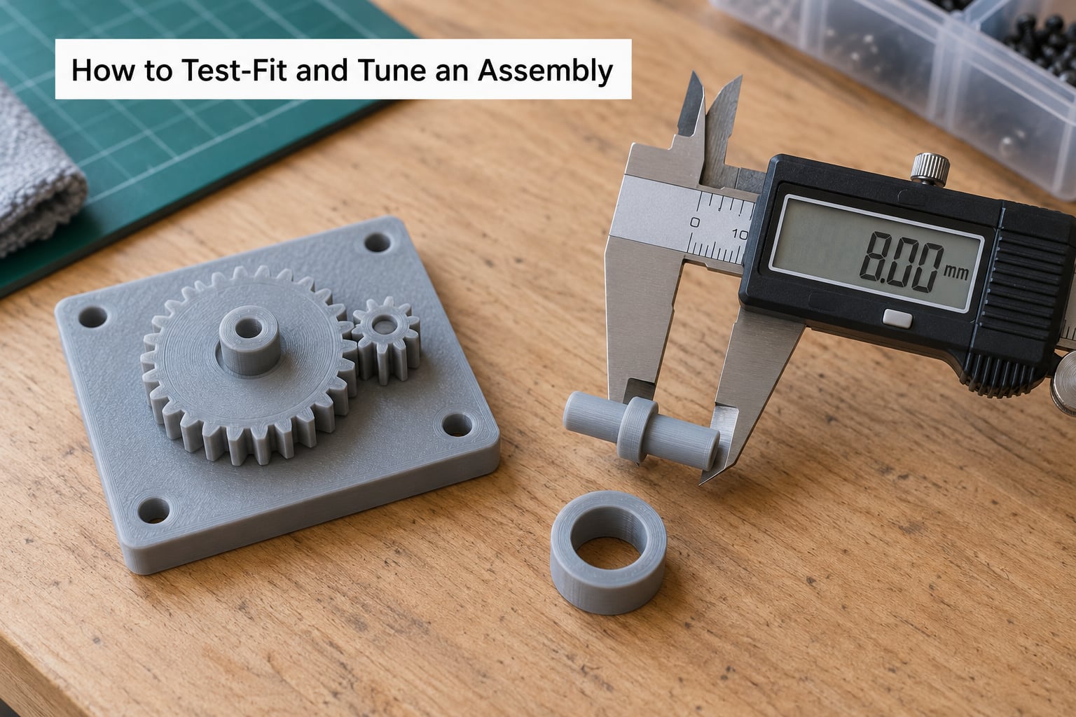
Print the joint, not the assembly. The fastest path to correct tolerances for 3D printed moving parts runs through a small coupon that contains the critical interface at full size.
- Build the coupon. Include the real hole, the real shaft, a range of clearances if you are searching (0.2, 0.3, 0.4 and 0.5 mm) and any curved or post-processed feature.
- Print it in the real orientation. A coupon on the bed tells you about bed-printed holes only. Test the vertical orientation separately if the real part uses it.
- Inspect before measuring. Look for stringing, seam blobs, delamination and lifted corners. A part with a visible defect will mislead you about dimensional error.
- Measure with the right tool. Calipers for outside dimensions, small bore gauges or pass pins for holes. Take three readings and average them.
- Assemble without force. If it needs a tool to go together, stop. Never press a printed joint together to make it fit.
- Run the motion test. A rotating joint should spin through a full revolution with a light drag. A sliding piece should move by gravity on a slight tilt.
- Adjust one variable and reprint the coupon. Change the slicer compensation or the model dimension, not both at once, or you will not know which one fixed it.
Define pass and fail before you start. A rotating joint passes if it turns through 360 degrees with no dead spot and no side load; fails if it stops anywhere in the rotation. A sliding piece passes if it travels its full stroke on a 15 degree tilt; fails if it creeps under its own weight on a flat surface. A snap fit passes if it holds with a firm pull and releases with a thumbnail; fails if it goes on without resistance or will not come off without heat.
Record the result. A note that says “0.3 mm hole gave 0.22 mm actual at 0.2 mm layer height in PETG” is worth more than any table on the internet, because it is true on your machine.
What Measurements and Tools Give the Best Results?
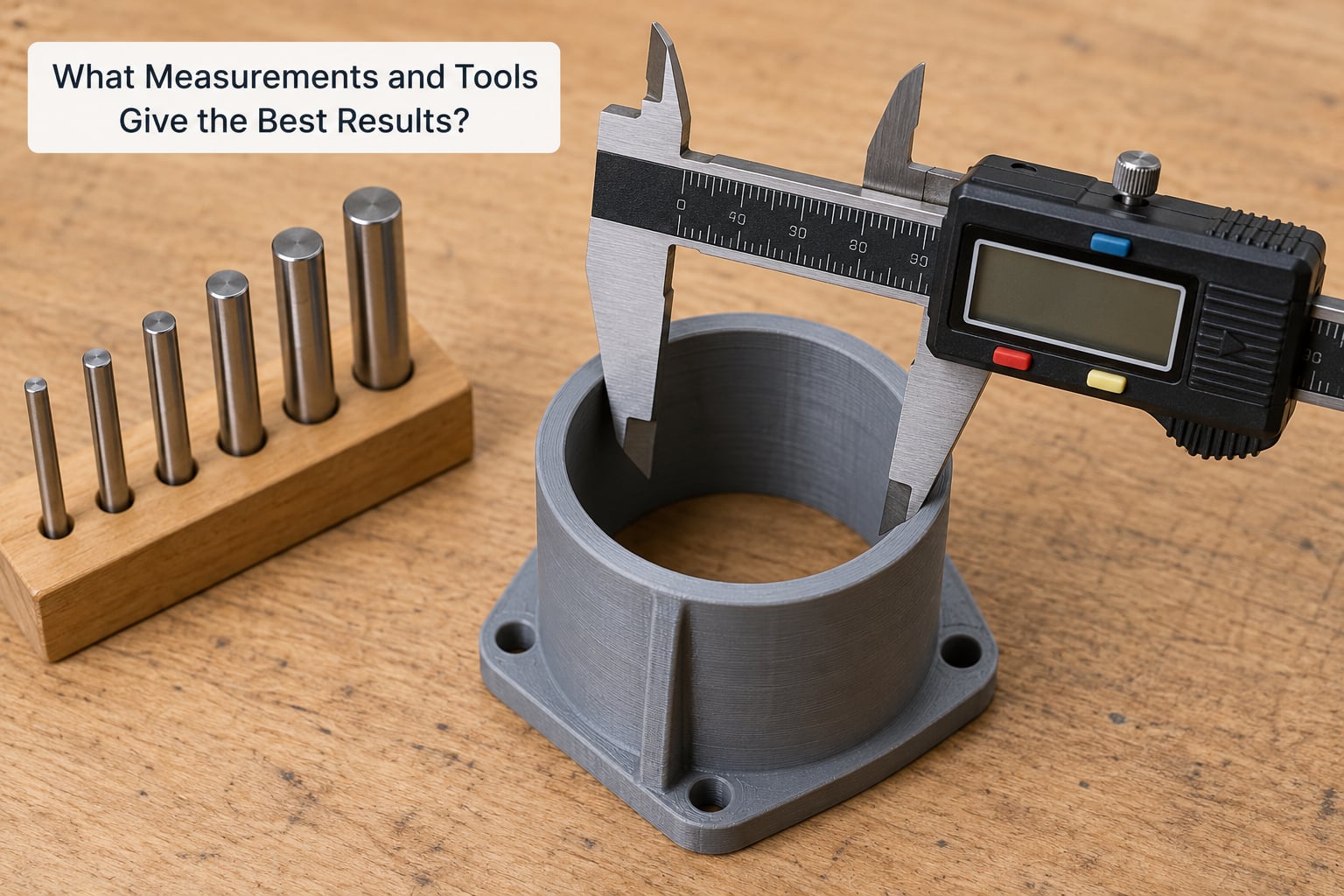
Each tool answers a different question. Knowing which one reaches for a specific measurement saves a lot of guessing.
| Tool | Good at | Limitation |
|---|---|---|
| Digital caliper | Outside dimensions, wall thickness, shaft diameters, quick checks on holes with an internal jaw | Resolution and accuracy vary; cheap units drift and cannot resolve 0.05 mm reliably |
| Outside micrometer | Shaft and pin diameters, where you need 0.01 mm resolution | Cannot measure a hole; contact pressure can push into soft plastic |
| Bore gauge | Inside diameters directly, including small holes | Expensive, and reading the dial on a soft printed surface needs a light touch |
| Feeler gauge | Gap widths and slot clearances where the gap is open on one side | Only works on accessible gaps, and the blade thickness itself is the limitation |
| Pass / fail pin gauges | Binary confirmation that a hole is above or below your limit, quickly and repeatedly | Tells you pass or fail, never how far off you are |
Measuring the actual printed part matters far more than trusting the slicer or the CAD file. The slicer reports what it was told, not what came out, and a CAD dimension is a request rather than a result.
Two habits help. Take measurements after the part has cooled fully and, for resin, after a complete cure, because both move slightly as they settle. And measure at several heights and around several positions, since a hole that is square in the CAD can come out slightly oval or tapered.
How to Fix a Too-Tight or Too-Loose Printed Part
Match the symptom to the fix rather than reaching for the same global scale every time. Most problems have one cause and one clean answer.
| Symptom | Likely cause | What to change |
|---|---|---|
| Hole smaller than modelled | Polygon rounding, thermal shrink, undersized extrusion | Set horizontal expansion to minus 0.05 or minus 0.1 mm |
| Part binds on the build plate only | Elephant foot at the base | Add a small chamfer, lift the part in the slicer, or increase first-layer cooling |
| Rotating joint grinds rather than turns | Seam burr inside the bore | Move the seam, or deburr with a fine file or scraper |
| Holes vary between prints | Flow, temperature or tension inconsistency | Run a flow test and a temperature tower, then re-check the first layer |
| Snap fit will not release | Root radius too tight, or material too stiff | Increase the root radius and add 0.1 mm clearance, or try a softer filament |
| Press fit loose after cooling | Material shrank during cooling | Model a deeper bore, add ribs, or switch to a low-shrink material |
| Layer split along the joint | Not enough layer adhesion for the load | Raise the layer height slightly, increase part wall count, or reorient the part |
| Everything is loose but consistent | Over-corrected slicer compensation | Reduce the negative expansion value, or scale the affected features only |
Two warnings. First, never assemble a tight printed joint with force. Plastic that has been forced into a hole will fail later at a spot with no visible damage, and printed parts carry almost no safety factor. Second, resist reaching for a global scale. If one interface is wrong, change that one interface.
And when reaming or drilling is the right answer, treat it as a deliberate design step rather than a rescue. Drilling out a tight hole to a target diameter works well, and reaming with a proper reamer gives a genuinely accurate bore, but a twist drill will wander and leave a burr. A pilot hole, a light cut and a final pass get you a cleaner result than fighting the drill.
Frequently Asked Questions
What is a good starting clearance for 3D printed moving parts?
Start at 0.3 mm for a rotating shaft in a bore, 0.4 to 0.5 mm for a sliding piece or print-in-place hinge, and 0.3 to 0.4 mm at the root of a snap fit. Resin usually needs only half of that. These are starting points, not answers: print a coupon at the real orientation, measure it, then adjust.
Should I scale the entire model or change only the moving fit?
Change only the moving fit whenever you can. A global scale factor shifts every dimension at once, so a joint that was already correct will drift out of tolerance and you will have no way to tell which change caused the new problem. Use slicer horizontal expansion to correct holes globally, and edit individual clearances in CAD.
Why does an FDM hole fit differently from the same hole printed in resin?
An FDM bore is built layer by layer from an approximated polygon, so the corners round inward and the hole finishes smaller, with seam blobs adding a burr. Resin cures as a smooth surface with far less rounding, which is why resin tolerances of 0.05 to 0.1 mm work reliably while FDM usually needs 0.2 mm or more.
Can I ream or drill an FDM part to correct a tight hole?
Yes, and it is often the most accurate fix available. Drill a pilot hole slightly under the target diameter, then step up slowly with a reamer for a clean round bore. Expect a little burr at the entry, and remember that drilling changes only that one feature, which is why it beats re-slicing the whole model.
How do temperature and material affect tolerances for 3D printed moving parts?
Hotter nozzles and higher chamber temperatures raise thermal contraction and shrinkage as the part cools, so the same model comes out smaller. ABS, ASA and nylon shrink noticeably and often need a scale compensation of 1 to 2 percent, while PLA and PETG are stable enough to design as modelled. Warm parts are also softer, so a joint that fits on a cold bench can bind in summer.
Conclusion
Start with a functional clearance rather than a number from a spec sheet, print a coupon that contains the critical interface at full size, measure it with a caliper or a bore gauge, and change one variable before you commit to the full assembly. Whether you are tuning tolerances for 3D printed moving parts on a printer you built yourself or tuning them for 2026 production runs, that loop is what separates a mechanism that moves from one that prints solid.