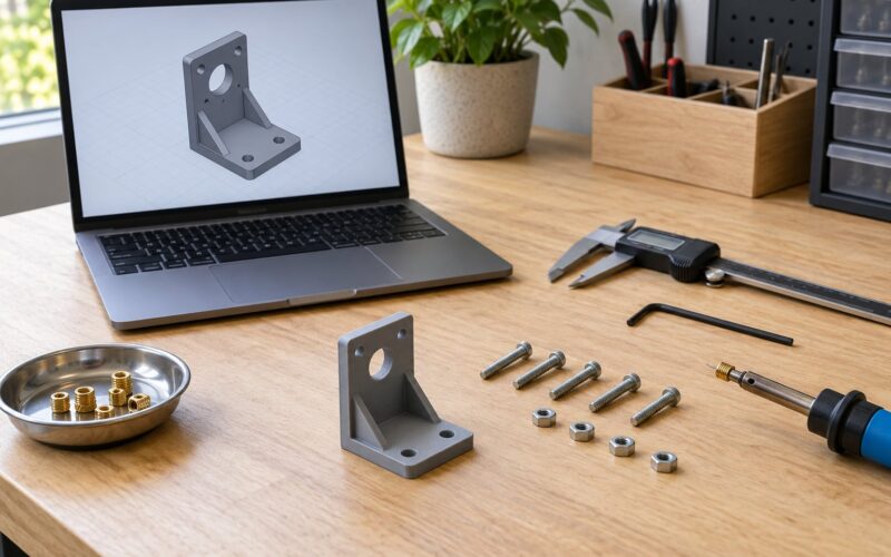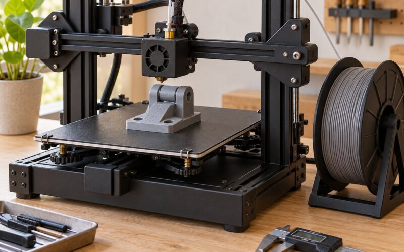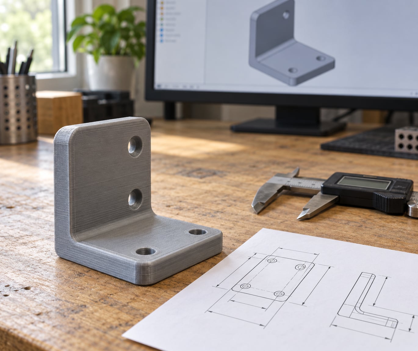
Modeling a part for 3D printing in Fusion 360 means building a 3D solid body in Autodesk Fusion, adding the geometry a printer can actually make — walls thick enough, overhangs shallow enough, holes opened up for shrinkage — and exporting that body as an STL or 3MF file for a slicer. A first printable part takes about an hour of modeling if the dimensions are already in front of you. The hard part is not the clicks; it is deciding what the printer will tolerate before you spend four hours of filament.
Fusion is free for personal use, runs on Windows and macOS, and has a browser version that behaves differently enough that I would not learn on it. Everything below is the desktop Design workspace. If a menu label differs slightly in your build, it is usually because Autodesk moved it, not because you are doing something wrong.
Table of Contents
- What You Need
- How to Model a Part for 3D Printing in Fusion 360: Step-by-Step
- Step 1: How to Model a Part for 3D Printing in Fusion 360
- Modeling an Object You Already Own With No Drawing
- Step 2: Create and Constrain the Base Sketch
- Step 3: Add Printable Features and Dimensions
- Step 4: Prepare the Model for the Printing Process
- Step 5: Inspect the Printable Model
- Step 6: Choose the Best Print Orientation
- Step 7: Export STL or 3MF and Prepare the File
- Common Mistakes
- Frequently Asked Questions
- Is Fusion 360 good for beginners making 3D-printable parts?
- Should I model in Fusion 360 or start with a mesh file?
- How do I set hole and clearance sizes for 3D printing in Fusion 360?
- Can Fusion 360 check whether my model is printable before export?
- Should I export STL or 3MF from Fusion 360 for 3D printing?
- Why won’t my 3D-printed threads fit even though the CAD model is correct?
- Conclusion
What You Need
Before you open Fusion, four things make the modeling session much shorter: a dimensioned reference, a chosen printing process, the printer’s real specs, and a slicer you already trust.
- A dimensioned drawing or a way to get dimensions. A PDF, a photo with calipers in frame, or the physical part itself. The drawing path is obvious; the calipers path is covered in Step 1.
- A chosen process. FDM, resin, or powder-bed. The process decides your minimum wall thickness, how you handle holes, and whether supports are a design problem or a slicer setting.
- Your printer’s actual numbers. Nozzle diameter, build volume, and layer height you intend to use. Fusion cannot guess these.
- The expected accuracy. Hobby FDM machines typically land somewhere around ±0.2 mm on a well-tuned part; the swing comes mostly from calibration, layer height, and material shrinkage rather than the machine brand.
- A slicer. Fusion builds geometry. The slicer decides supports, infill, layer height, and the toolpath. You need both.
Fusion’s personal-use license covers non-commercial work. It also caps you at ten live, editable documents at a time; past that you get a read-only limit message and you either archive or download the finished files. Save work into a Project, then a Design inside it, so exports land somewhere predictable.
One more prep item that pays off later: make a quick test coupon. A 20 mm cube with two differently sized holes and a short length of modelled thread tells you in ten minutes of print time exactly how much your printer oversizes holes. Every compensation value in this guide is worth testing on your own machine rather than trusting mine.
How to Model a Part for 3D Printing in Fusion 360: Step-by-Step
The eight moves below are the whole job, from a blank document to a file your slicer accepts:
- Define the part, the process, and the print orientation
- Set the document units and choose a sketch plane
- Create the base sketch and constrain it fully
- Extrude the profile into a solid body at printable wall thickness
- Add holes, pockets, fillets, chamfers, and threads
- Apply hole, thread, and corner compensation for your printer
- Inspect with Measure, Section, and body checks
- Rotate for orientation, then export STL or 3MF with high refinement
Step 1: How to Model a Part for 3D Printing in Fusion 360
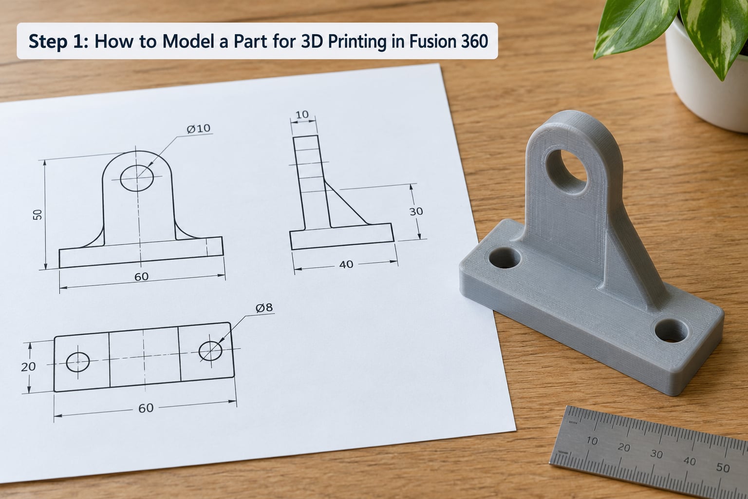
Start by writing down what the part does and how it will be held. A bracket that carries a 2 kg load with a screw through one hole is a different object from a shelf clip that just rests on something. The load path tells you where walls need to be thicker and where you need a fillet rather than a sharp internal corner.
Then decide the print orientation, because it changes the model. A part that must lie flat needs its largest face on the build plate. A part that hangs from a wall wants its layers stacked so the load runs through them, not across them.
Choose the starting geometry based on what you have:
- A constrained sketch when you know the profile: plates, brackets, enclosures, flanges. This is the parametric path and the one to learn.
- An imported mesh when a 3D scan is your only reference. Import it with Insert > Mesh, then use Mesh > Convert to BRep to turn it into a solid body you can fillet and cut.
- An existing body or component when you are making a second part that fits the first. Copy the body, add an as-built joint between the two, and the fit stays honest.
Chambers, bodies, and components are the concept that trips up nearly everyone starting out. A component is a container in the browser that holds a rigid assembly of one or more bodies. A body is a single solid piece of material. A chamber is a space between the outer body and an offset inner cavity, so you can size a hollow shell directly instead of cutting two bodies apart.
For document setup: File > New Design > Manufacturing, set units to millimeters, and stay in the Design workspace. Manufacture and Render are for CAM and rendering; you will not need them for printing prep. Sketch on the XY plane for a part that will sit flat, or select a face and choose Create Sketch on the Face when a profile needs to follow an existing surface.
Modeling an Object You Already Own With No Drawing
This is the most common question on the forums and the least answered one, so here is the sequence that works:
- Photograph the part from front, side, and three-quarter views with a ruler or calipers visible for scale.
- Measure the three overall bounding dimensions with digital calipers and write them down in millimeters.
- Measure every feature you actually need: hole diameters and their spacing, wall thickness by measuring an exposed edge, slot widths, mounting centers.
- Sketch the main profile as a rectangle using the bounding dimensions, then add each measured feature as a constraint rather than eyeballing it.
- Print a test coupon of the two features you are least sure about before printing the whole part.
- Measure the coupon, adjust the model, print again. That loop is how experienced users converge on a part that actually fits.
You do not need every dimension. You need the ones the part has to match, and those you measure. Cosmetic details on a replacement handle can stay approximate.
Step 2: Create and Constrain the Base Sketch
Select a plane in the browser or click a face, then hit Create Sketch. In the sketch environment, choose the profile tool that matches your geometry: rectangle for a plate, circle for a boss, polygon for an outline, slot for an elongated hole.
Draw roughly, then constrain. Fusion’s constraints are the actual content of the model, and a sketch held together by dragging geometry is a sketch that will break the first time a dimension changes. Dimension constraints drive size; geometric constraints control relationship. Skipping this is the most common reason a project stalls halfway through learning how to model a part for 3D printing in Fusion 360.
A few habits worth forming on the first project:
- Fully constrain the sketch before extruding. The sketch dialog shows the degree-of-freedom count; it should be zero.
- Anchor the origin first so the profile cannot drift when you add constraints.
- Use symmetry constraints instead of dimensioning the same feature twice. Half the work, half the error.
- Watch for accidental zero-length geometry. Two lines that land on top of each other make a shape that extrudes into nothing or throws a self-intersection error.
- Add user parameters for anything you may resize later. A phone case driven by a width and height parameter can become a tablet case in about fifteen seconds.
Before you leave the sketch, zoom in and read the dimension values back. A profile that looks square on screen is often not square, and you will not catch it again until the print fails.
Step 3: Add Printable Features and Dimensions
Extrude the constrained profile to your target height, which for most FDM parts equals the wall thickness the toolpath needs — roughly three to four perimeters on a 0.4 mm nozzle, or about 1.2 to 1.6 mm. Making the solid taller is fine; making the solid thinner than what the slicer can lay down in one perimeter is not.
Now add the features:
- Holes: the Hole Wizard gives you a full set of standard hole types and, importantly, lets you model clearance or threaded holes per a standard rather than guessing at a diameter.
- Pockets and slots: pocket depth drives whether the floor needs support. A shallow pocket floors itself; a deep vertical one usually does not.
- Lofts, revolves, and extrusions: loft for a tapering body, revolve for anything circular around an axis. Both print fine as long as the angle from vertical stays inside the self-supporting range.
- Fillets and chamfers: every internal corner gets a radius. Sharp internal corners concentrate stress and print as a stress riser where layers meet.
For threads, the Thread tool needs care. If you leave the Modelled checkbox clear, you get a cosmetic thread — a groove drawn on the surface that does not exist in the print. Tick it, pick an ISO Metric profile, and set the designation (for example M10x1.5) and class (6g external, 6H internal). Then compensate, because a mathematically correct thread binds on a real printer.
Know which details to simplify. Engraved logos, text under about 8 mm tall, and holes smaller than two nozzle widths usually turn into blobs. Snap-fit features need generous draft angles. Detail that survives a sanding pass is worth modeling; detail that disappears is wasted modeling time.
Step 4: Prepare the Model for the Printing Process
This is where CAD meets physics. Nominal CAD dimensions are not printed dimensions, and the gap between them is where first-print failures live.
| Feature | Value to use | Why |
|---|---|---|
| Minimum wall thickness | 3 to 4 perimeters, roughly 1.2 to 1.6 mm | Fewer perimeters print as gaps or single ragged lines |
| Internal corner radius | 0.8 to 1.2 mm | Relieves stress and removes the sharp layer corner |
| Self-supporting overhang | 45 degrees or shallower | Steeper angles droop into unsupported stringy edges |
| Hole for an M3 fastener | 3.2 to 3.4 mm nominal | Printed holes come out undersize; open the CAD hole up |
| Printed internal thread | Start 10.1 to 10.2 mm for an M10, then Offset Face +0.05 to +0.15 mm | Threads bind without compensation |
| Printed external thread | Scale to 0.98 to 0.99 | Same reason, from the other direction |
| First-layer edge | 0.5 mm chamfer on the bottom face | Limits elephant foot where the first layer squishes out |
Internal and external threads are the case most people lose a print to. The same recipe shows up consistently across hobby printing communities: model the male side first, apply a scale factor of 0.98 to 0.99 or offset the female face by roughly 0.1 mm, print a 10 mm test coupon, and adjust. Coarse pitch threads print stronger in soft materials like PLA, and printing threads vertically with the layer lines running along the thread holds far better than laying them flat.
Clearance and interference fits follow the same idea. Design for a sliding fit with a couple of tenths of a millimeter of slack if the part has to move, and note that most FDM printers across brands land in a comparable tolerance band, so material shrinkage and layer height matter more than the machine you own.
Look for the geometry that will fail silently:
- Unsupported regions: anything facing downward past 45 degrees, unless you intend to support it.
- Thin walls: below two nozzle widths, they print inconsistently or not at all.
- Trapped powder or resin: an internal cavity a brush cannot reach ruins a powder or resin print and is only visible after cleaning.
- Inaccessible cavities: an internal pocket you cannot clean or remove support from is a redesign, not a slicer setting.
- Long unsupported bridges: more than about 50 mm and most FDM printers sag.
Process differences are real but smaller than the internet suggests. Resin washes detail far better than FDM and holds tighter holes, which means less hole compensation. SLS or other powder processes have no overhang problem at all, so the 45-degree rule stops mattering — but trapped powder becomes the central design constraint, and walls need to be thick enough to be self-supporting in the tray.
Step 5: Inspect the Printable Model
Fusion will not tell you whether your part is printable, but it will tell you whether it is what you meant to build. Use Measure to check wall thickness and hole diameters, Section to look inside cavities, and the Analysis workspace’s interference and body checks to confirm the solid is closed and has no self-intersections.
Verify against a short list before exporting:
- Every wall meets the minimum thickness for your nozzle.
- Clearance holes clear the fasteners that will actually go through them.
- No sharp internal corners remain un-filleted.
- Fillets landed — Fusion silently skips a fillet that cannot fit and tells you in the dialog, and skipping it is the easy mistake to miss.
- The body is a single closed solid with no stray surfaces floating in the browser.
- Smallest features are at least two nozzle widths across.
If a measurement is wrong here, every downstream step inherits the error. Fixing it takes one edit; fixing it after a 6-hour print takes four.
Step 6: Choose the Best Print Orientation
Orientation is a design decision, and it belongs here in CAD, not at the slicer. Drag the body in the viewport and rotate it until the biggest flat surface sits on the virtual build plate. Every millimeter of surface you gain there is one less millimeter of support.
Rotate the body so loads run through layers rather than peeling them apart, so threaded features print in the direction that holds strength, and so cosmetically important faces end up on the top or front of the print. If two orientations both work, pick the one with less support material and fewer islands.
Worth repeating: Fusion’s modeling tools do not set supports, infill, layer height, or bridging. Those all live in the slicer, and the final orientation call belongs to the slicer’s preview. Use the CAD orientation as a strong starting position and confirm it there.
Step 7: Export STL or 3MF and Prepare the File
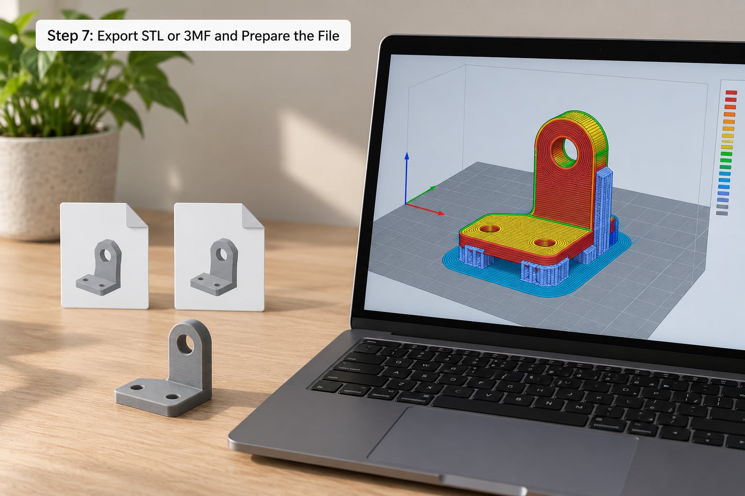
Export from the Design workspace with File > Export, or right-click the body and choose Save As Mesh. Pick a folder outside the project so your design files and mesh files stay separate.
Set the format, then set refinement. For STL, choose high refinement so fillets and holes come through as smooth surfaces rather than visible facets. Leave the units at millimeters unless you are printing in a different unit system and have checked the slicer matches — a scale mismatch between CAD and slicer is the single most common cause of a part printing at the wrong size.
Name the file with something you will recognize in three months: part name, material, and a date or revision, like bracket_v2_petg. Get this wrong and you will print the old bracket from the wrong material.
STL is fine for most prints. It stores only geometry, so it carries no units, no colors, no material assignment, and no part identity. 3MF carries units and assembly structure and keeps multiple bodies and colors in one file, which makes it the better choice when you are exporting several pieces of an assembly that must stay together.
Before you print, open the file in the slicer and confirm four things: the model is at the size you expect, the orientation is the one you planned, the support and layer settings match your assumptions, and there are no mesh warnings about non-manifold geometry. An exported file is not a printable part until the slicer agrees.
Common Mistakes
Most of the frustration people report in the forums comes from a handful of repeatable errors:
| Symptom | Likely cause | Fix |
|---|---|---|
| Model breaks when you change a dimension | Underconstrained sketch | Fully constrain it; check degree of freedom is zero |
| Extrude produces nothing or errors | Zero-length or self-intersecting sketch geometry | Zoom in and remove the overlapping profile |
| Hole prints too small | No hole compensation for shrinkage | Increase the CAD hole diameter and print a coupon |
| Threads bind or strip | No compensation, or cosmetic thread not modelled | Tick Modelled, then Offset Face or Scale by the values above |
| One dimension changed and everything moved | Scaling the body instead of editing one parameter | Use user parameters and change the single value |
| Feature shows a red cross on the timeline | Upstream sketch changed and broke the feature | Roll the timeline back to the failing feature and fix it there |
| Overhangs discovered after modeling | Orientation never decided in CAD | Rotate the body and redesign those faces |
| Part prints at the wrong scale | STL imported with wrong units in the slicer | Check slicer units and measure the first layer |
| Corners snap off in use | Sharp internal corners left un-filleted | Add 0.8 to 1.2 mm fillets |
Two checklist items catch most of the rest. Before export: is the sketch fully constrained, and are all features showing green in the timeline? Before the print: has the slicer preview shown the orientation, supports, and first layer at the size you measured in CAD?
And expect iteration. The first print of any new part is a test coupon in disguise, not a deliverable.
Frequently Asked Questions
Is Fusion 360 good for beginners making 3D-printable parts?
Fusion 360 is a solid starting point for beginners because it is free for personal use and its Design workspace does exactly what printing needs: constrained sketch, extrude, fillet, hole, and mesh export. The learning curve is steeper than browser-based tools like TinkerCAD, and the browser version behaves differently enough that desktop is worth using. Plan your first two or three parts as simple brackets and enclosures before attempting mechanisms.
Should I model in Fusion 360 or start with a mesh file?
Model in Fusion when you know the dimensions, because a constrained sketch stays editable: change one value and the whole part updates. Start from a mesh when you only have a 3D scan of the object, importing it with Insert u0026gt; Mesh and converting it to a bRep solid body so you can cut and fillet it. Meshes have no parametric history, so edits after import are manual and slower.
How do I set hole and clearance sizes for 3D printing in Fusion 360?
Model the hole larger than the fastener, because printed holes come out undersize. On a 0.4 mm nozzle, an M3 clearance hole is usually drawn at 3.2 to 3.4 mm rather than 3 mm. Use the Hole Wizard to set the standard and clearance type instead of typing raw diameters. Print a coupon with two hole sizes, measure with calipers, and adjust the CAD values by the difference you measured.
Can Fusion 360 check whether my model is printable before export?
Fusion checks geometry, not printability. Measure, Section, interference checks, and body validity confirm the solid is closed, correctly sized, and free of self-intersections. It cannot judge wall thickness against your nozzle, overhang angles against your support strategy, or trapped cavities. Those checks are yours to make in CAD, then confirm in the slicer preview before you print.
Should I export STL or 3MF from Fusion 360 for 3D printing?
STL is the default and works for almost everything: it stores geometry only, with no units, colors, or material data, and every slicer reads it. Choose 3MF when you are exporting an assembly of several printed pieces, since it keeps bodies, colors, and units together in one file. Use high refinement on either format so fillets and holes are not faceted.
Why won’t my 3D-printed threads fit even though the CAD model is correct?
A perfect CAD thread still binds because printed threads are built from layers, not machined surfaces. Tick Modelled on the Thread tool or the thread will not exist in the print at all. Then compensate: for an M10 internal thread, start at 10.1 to 10.2 mm and add an Offset Face of +0.05 to +0.15 mm, or scale an external thread to 0.98 to 0.99. Print a test coupon before committing.
Conclusion
A printable Fusion 360 model is not the result of one operation. It comes from a fully constrained sketch, features added in order, clearances adjusted for the printer and material in front of you, an orientation chosen before export, and a slicer preview that agrees with all of it.
Start with the part’s dimensions and pick your process, because those two decisions drive everything else. Then work one CAD stage at a time, checking each before moving on. Print a coupon early, measure it with calipers, and let that measurement set your compensation values. That loop, not the software, is what gets a part fitting on the second try.