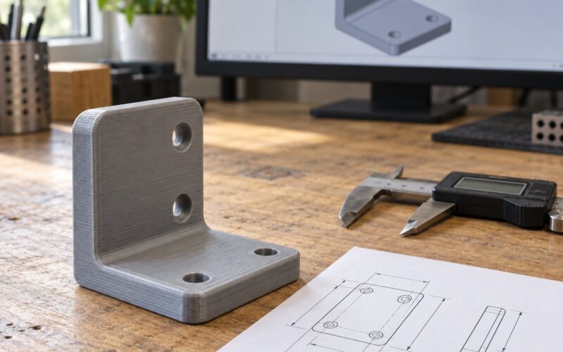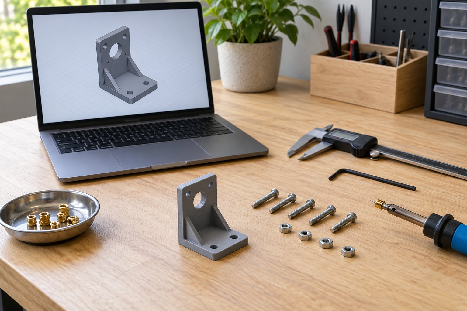
There are four real ways to add threads to 3D printed parts: model the thread directly in CAD, press a heat-set insert into a printed hole, embed a nut during the print, or cut the threads after printing with a tap. For most functional parts a brass heat-set insert is the answer, because it gives you metal threads that survive repeated assembly without the guesswork of designing a printable thread.
This guide walks through the whole job, from picking a method to verifying a joint holds. Budget about two hours for your first printed thread, most of it spent printing test coupons rather than the real part.
Table of Contents
- What You Need
- Step-by-Step: How to Add Threads to 3D Printed Parts
- Step 1: Choose the Right Thread Method
- Step 2: Set the Thread Standard and Dimensions
- Step 3: How to Add Threads to 3D Printed Parts in CAD
- Step 4: Prepare the Part for Printing
- Step 5: Test and Assemble the Threaded Part
- Common Mistakes
- Threads Seize on the First Screw
- Fine Threads Like M3 Strip or Snap
- Heat-Set Inserts Spin in the Hole
- The Part Cracks During Insertion
- Nozzle Collides During a Nut Pause
- Glued Nuts Let Go
- Wrong Pitch in the Model
- Misaligned or Warped Holes
- Frequently Asked Questions
- Can you print threads directly into a 3D-printed part?
- What is the best material for 3D printed threads?
- Should I model threads in CAD or use a heat-set insert?
- What clearance should I use for a threaded hole?
- Can you heat-set inserts into a resin or SLA print?
- How do I fix threads that stripped on the first print?
- Conclusion
What You Need
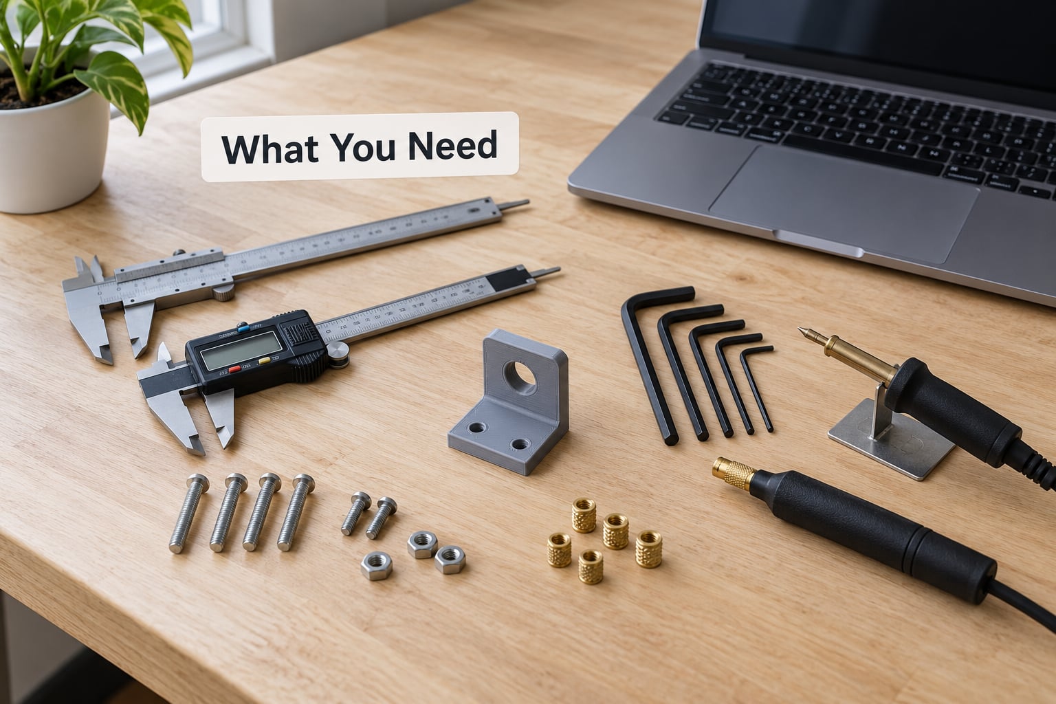
You do not need much, but you do need a caliper. Every technique below depends on a hole that is the right size, and eyeballing a printed hole is how parts end up stripping on the first screw.
- CAD software with a thread feature — Fusion 360, SolidWorks, Onshape, FreeCAD, Inventor and Shapr3D all ship one. FreeCAD’s Part workbench handles threads; OpenSCAD needs a library.
- Digital calipers — for measuring printed holes and confirming a printed peg against a real fastener.
- A thread pitch gauge or a caliper set — cheap plastic gauges are fine, and they save you from picking a 0.8 mm pitch when you meant 1.0 mm.
- Reference dimensions — the manufacturer’s hole diameter chart for your inserts, or a standard thread table for the fastener you plan to use.
- Heat-set inserts and a soldering iron — brass inserts in the sizes your model calls for, plus an iron with a small conical tip. A dedicated heat-set tip is nicer but not required.
- A tap set and a hand drill — if you plan to tap threads, you need the matching tap and a way to hold the part so it will not crack.
- Rigid filament for test coupons — PETG, ABS, ASA or nylon. Print a small coupon of every feature you are unsure about.
- Threadlocker rated for plastics — ordinary threadlocker can craze certain polymers, so check the bottle before it goes anywhere near a printed part.
Step-by-Step: How to Add Threads to 3D Printed Parts
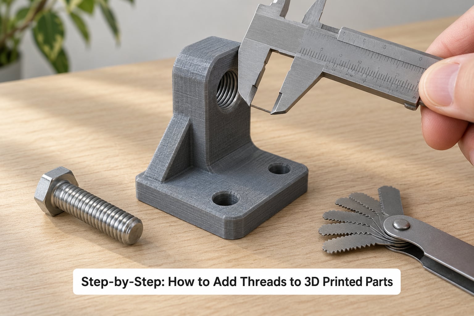
Step 1: Choose the Right Thread Method
Pick the method before you model anything, because it changes the geometry completely. Modeled threads make the part heavier and fiddlier; inserts make it simpler and stronger.
- Modeled threads in CAD — best for light-duty parts, cosmetic threads, bottle caps and hand knobs, and for anything where the joint is assembled once or twice. Avoid it where a bolt will be torqued repeatedly or where the threads carry load across layer lines.
- Heat-set inserts — the default for functional parts. Enclosures that open and close, robot joints, camera mounts, workshop jigs, anything bolted together more than a handful of times.
- Embedded nuts — strongest option and the least forgiving. Worth it for high-load joints where you want genuine pull-out strength and you can live with a print pause.
- Tapped holes and self-tapping screws — good for heat-loaded, low-cycle joints in stiff material, and the only clean option on some resin prints. Plastic threads wear out; brass does not.
One rule of thumb: if the connection is structural or repeated, use metal threads. Printed threads are for handling, alignment, and light retention.
Step 2: Set the Thread Standard and Dimensions
You need four numbers before you draw anything: the nominal diameter, the pitch, the thread form, and how much thread you want engaged. Get these from the fastener itself or from a standard table, not from memory.
Metric and imperial are the two traps here. M6 at 1.0 mm pitch has nothing to do with 1/4-20 UNC, and mixing them produces a hole that looks close and refuses to work. A pitch gauge settles it in a second. Check the marking on the bolt head or the packaging before you commit to a standard.
For strength, plan on one diameter of thread engagement. Two diameters is generous, and going past that mostly adds print time and invites cracking at the mouth of the hole.
Step 3: How to Add Threads to 3D Printed Parts in CAD
Every modern CAD package applies a thread as a feature on a cylinder rather than as a drawn helix, which saves a lot of pain. The workflow is nearly identical everywhere.
- Create or select the cylindrical face that will become the hole.
- Apply the thread feature and pick the standard from the drop-down: metric coarse, metric fine, UNC, or UNF.
- Enter the size and class. For printed threads, use a coarse standard; fine pitches are too small for reliable extrusion and usually strip.
- Terminate the thread with a blind hole or a through hole, and set the thread depth a diameter deeper than the hole so the drill point has clearance.
- Add a chamfer at the mouth of the hole. A 45 degree lead-in chamfer the diameter of the hole is a sensible starting point, and it stops the bolt from chewing the first layer it lands on.
Now engineer the clearance. FDM extrusion comes out slightly wider than the nominal nozzle path, so a hole modeled at exactly 3.0 mm will come out under 3.0 mm and will not accept a 3 mm peg. Offsetting or undersizing the modeled hole by roughly 0.15 to 0.2 mm is the standard compensation, and it is the number most people get wrong on their first attempt.
For threads modeled into the plastic itself, choose a thread form that prints. A V-thread has a sharp crest that no nozzle can reproduce cleanly. ACME and trapezoidal profiles have flat flanks and flat crests, which slice into pathable geometry and hold up far better. Most makers land on ACME.
For insert pockets, draw a tapered hole rather than a straight one. A slight draft makes insertion far easier and gives the knurled exterior something to grip. Leave a small relief well at the top so displaced plastic has somewhere to go instead of bulging the surface, and keep at least four walls around the hole for the surrounding strength.
If you use a nut pocket instead, orient the pocket so the nut enters from a direction you can reach. An upward-facing pocket on the underside of a part means flipping the whole assembly over each time you assemble it.
Step 4: Prepare the Part for Printing
Threads fail for print reasons as often as design reasons, and the slicer is where most of those get fixed.
- Orientation — print threaded features vertical whenever you can. A thread printed on its side collects the weakness of every layer line around its full circumference, and no amount of wall count saves it.
- Layer height — go finer where threads are. Sharp detail needs the layer lines to be small; a coarse layer height rounds off crests and eats your clearance.
- Walls — three or four perimeters around a threaded hole is the floor, not the goal. Five or six around an insert seat is better. More walls means fewer voids, and voids are what let an insert spin or a hole crack.
- First layer and hole quality — printed holes come out slightly smaller than modeled. If a hole is a squeeze fit when it should be a slip fit, look at your first layer before you change the model.
- Infill — solid infill inside the pocket walls helps, but do not count on infill for strength where a load is applied. The perimeters do that work.
For material, rigidity matters more than raw strength. PLA is brittle and cracks under torque once a screw is snug, so it is a poor host for threads. PETG creeps and gives slightly but tolerates a fastener. ABS and ASA hold heat and dimension better, and nylon is the pick for anything that sees load or abrasion. Resin prints cannot be heat-set at all, because the plastic will not melt and re-flow around the insert, so a stepped hole with epoxy is the resin route.
Step 5: Test and Assemble the Threaded Part
Test before you trust. Print a coupon that contains every feature you plan to use, ideally at the same orientation and on the same printer, because a thread that works on a cube can behave differently on a tall part.
Check the fit in stages. Start the bolt in by hand — it should seat with light resistance, not force, and not fall in loose. If it drops straight in with no drag, your clearance is too generous. If it stops dead, the hole is undersized. Then run it down fully and note the torque. Repeated tightening and loosening is a better test than a single hard pull.
For heat-set inserts, the install routine the community converged on works well: warm the iron a little above the print temperature, touch the insert to the tip first so it starts to soften, then press it into the hole until it is roughly 90 percent of the way down. Finish it flush with a flat metal object applied to the top face. Deep inserts grip along their full length; shallow ones rely on the mouth alone and pull out far sooner.
Finally, load the joint the way it will actually be loaded. A screw pulling outward from the insert, in other words tightening into a direction that draws the insert deeper into the plastic, gives you much more strength than the same joint in reverse. If you can, orient the fastener that way.
Common Mistakes
Most thread failures are one of a handful of recurring problems, and each has a specific fix.
Threads Seize on the First Screw
Threads that fuse to the fastener almost immediately are usually an extrusion-width problem, not a design problem. The path width closes the gap you paid for in the model. Print a single-layer test of the profile, then increase your offset until the bolt turns freely with a clean, unbroken thread flank.
Fine Threads Like M3 Strip or Snap
Below M4, FDM struggles to place a sharp thread form accurately. This is a machine limit more than a mistake. Move up one size, switch to ACME, or use an insert so the plastic never has to carry the thread itself.
Heat-Set Inserts Spin in the Hole
An insert that rotates when you tighten the bolt means the hole is too large or the walls are too thin. Drop the hole diameter one step if your chart allows, and raise the wall count around the seat to four or more. Short inserts also need a small dimple or cross-hole in the pocket to give the knurling something to bite into.
The Part Cracks During Insertion
Overheating the plastic or forcing a cold insert into a cold hole causes this. Let the part warm to roughly hand-warm, use an iron that is only 10 to 20 degrees above the print temperature, and stop pushing once the insert is seated. Cracks also show up when the hole is close to a wall or a stress concentration, so leave solid material all around.
Nozzle Collides During a Nut Pause
The pause-at-layer nut method is unforgiving, because the nozzle travels back over finished plastic to start the next layer. Drop the nozzle to a small layer height before the resume, make sure the first layer over the nut is not too hot, and design the pocket so the nut sits below the current layer rather than above it. Nozzle-brushing on a corner also lifts the part, so keep the pocket away from sharp external edges.
Glued Nuts Let Go
A nut dropped into a pocket and glued often fails because of contamination or a cold mating surface. Degrease the pocket, roughen it slightly, use a plastic-compatible epoxy, and hold the nut square while it cures. This is the method where a dry mechanical fit matters most — if the nut rattles, glue has to carry the whole load.
Wrong Pitch in the Model
A hole cut for 1.0 mm pitch will not accept a 0.75 mm pitch bolt no matter how much you change clearance. Verify the pitch with a gauge against the real fastener before you commit to a print, and keep your models on the standard your hardware actually uses.
Misaligned or Warped Holes
A hole split across two angled surfaces is not a hole, it is a trap for the bolt threads. Keep cylindrical features coaxial, avoid placing a threaded hole on a sloped face, and add enough perimeter support so the walls print vertical. For resin prints, make sure the part is fully cured and stress-relieved before you tap or fit anything into it.
Frequently Asked Questions
Can you print threads directly into a 3D-printed part?
Yes, and they work well for light-duty joints. Directly printed threads succeed best in FDM prints from rigid, dimensionally stable material like PETG, ABS, ASA or nylon, and they need a printable thread form such as ACME or trapezoidal rather than a sharp V-profile. The catch is accuracy: a modeled 3.0 mm feature rarely prints at 3.0 mm, so you must offset the hole or the peg and print a test coupon first. Printed threads also wear out quickly under repeated assembly.
What is the best material for 3D printed threads?
Rigid, dimensionally stable materials are the best hosts. PETG is a practical choice for light-duty threaded parts because it tolerates a fastener without cracking. Nylon and carbon-fiber or glass-fiber reinforced filaments hold up better under load and heat, at the cost of a harder print. PLA is the worst option for threads because it is brittle and tends to snap at the mouth of a tightened hole. Resin is dimensionally excellent but cannot be heat-set.
Should I model threads in CAD or use a heat-set insert?
Model threads when the part must stay light, simple to print, and used only a few times, such as a cap or a light retaining knob. Use a heat-set insert when the joint needs real strength, accurate repeatability, or repeated assembly and disassembly, because the insert gives you metal threads and a mechanical bond into the surrounding plastic. If you are still deciding, the insert is the safer default and most functional parts are better for it.
What clearance should I use for a threaded hole?
Do not estimate from the fastener’s outer diameter. Use your CAD package’s standard thread and clearance-hole features, then apply a printing offset of roughly 0.15 to 0.2 mm so the extruded hole prints slightly larger than modeled. The right clearance depends on the metric or imperial standard, the material, and your printer’s calibration, which is why a small test coupon is worth more than any table of ideal numbers.
Can you heat-set inserts into a resin or SLA print?
Not properly. Heat-setting works by melting and re-flowing thermoplastic around the knurled insert, and cured resin will not flow, so the plastic just crumbles or cracks. For resin parts, drill a stepped hole sized to the insert, seat it, and bond it in with a plastic-compatible epoxy or cyanoacrylate, keeping the bonded joint clear of heavy load. Printed resin threads themselves hold dimensional accuracy well but remain brittle under torque.
How do I fix threads that stripped on the first print?
Drill the stripped hole out to the next larger size and install an insert, which is usually faster than trying to repair the thread. If you want to keep the printed thread, add a thin layer of solvent-welded filament or a printed collar around the hole to build up material, then re-cut it. In the design, the real fixes are more perimeters around the hole, a coarser or ACME profile, and a chamfer so the fastener stops chewing the first layers.
Conclusion
Start here: model a small coupon with the hole and thread size you plan to use, print it vertically in PETG, and hand-fit a real bolt. Whatever clearance that coupon teaches you goes straight into the real model.
For the part itself, use a heat-set insert with a tapered pocket, four or more walls, and a chamfer. It takes ten minutes of modeling to save you an afternoon of chasing a joint that seizes on the first turn. Once the pattern works, keep the coupon in your parts bin for the next project.