A print in place hinge prints as one solid part, with the pin already sitting in its socket when the part comes off the build plate. To make one work, you need a radial clearance of about 0.20-0.30 mm per side in PLA, the pin printed on the Z axis, and slicer settings that stop the gap from filling with plastic. Get those three right and the joint moves straight off the plate.
Here is the thing that trips up most people: there is no tolerance field in your slicer. No global setting, no firmware option, nothing called “print in place.” The gap is a number the model designer baked into the geometry, and your job is to make sure your printer is accurate enough to honour it — or to compensate for it in the one or two places a slicer does expose.
This guide covers how to print print in place hinges from a downloaded model or one you design yourself, starting with the clearance numbers and ending with what to do when the joint comes off the bed fused solid.
Table of Contents
- What You Need to Print In Place Hinges
- Step-by-Step: How to Print Print in Place Hinges Without Fusing
- Check the Model and Hinge Clearance
- Choose the Orientation
- Set Materials and Temperatures
- Slice Without Disrupting the Axis
- Print, Cool, and Test the Motion
- Common Mistakes
- Frequently Asked Questions
- Can you print a print-in-place hinge in PLA or PETG?
- What layer height is best for a reliable print-in-place hinge?
- Why does my print-in-place hinge bind or not move?
- Do print-in-place hinges need supports?
- How strong should the hinge axis be for repeated movement?
- How do I fix an STL that is not designed for my printer?
- Conclusion
What You Need to Print In Place Hinges
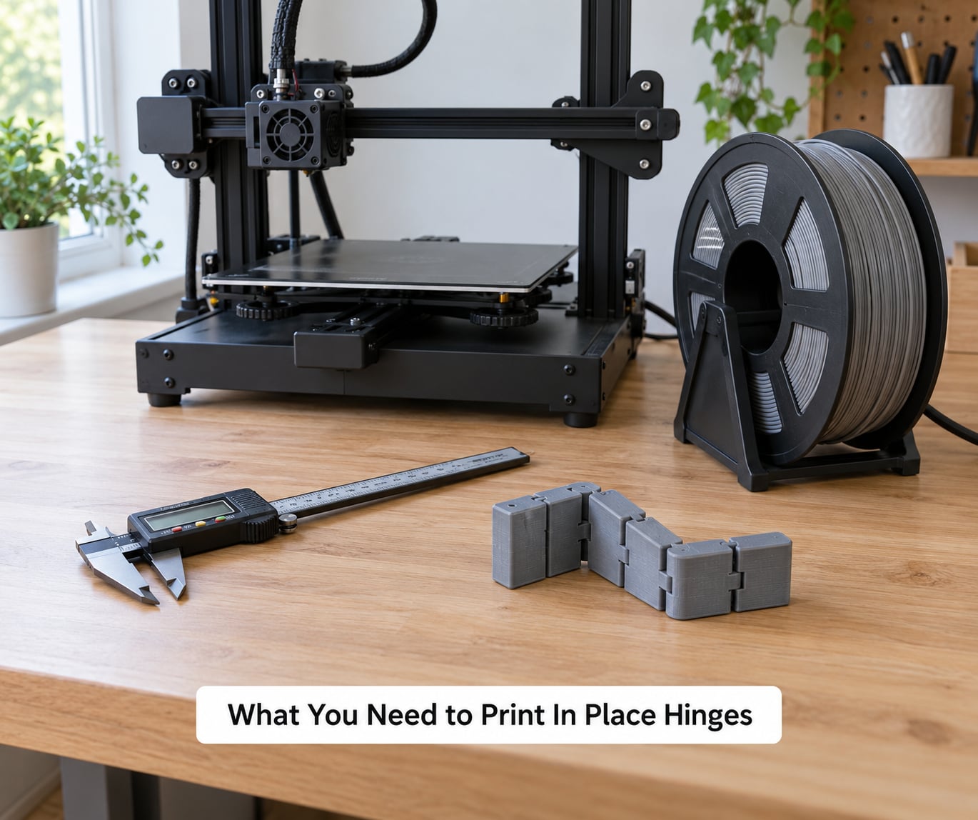
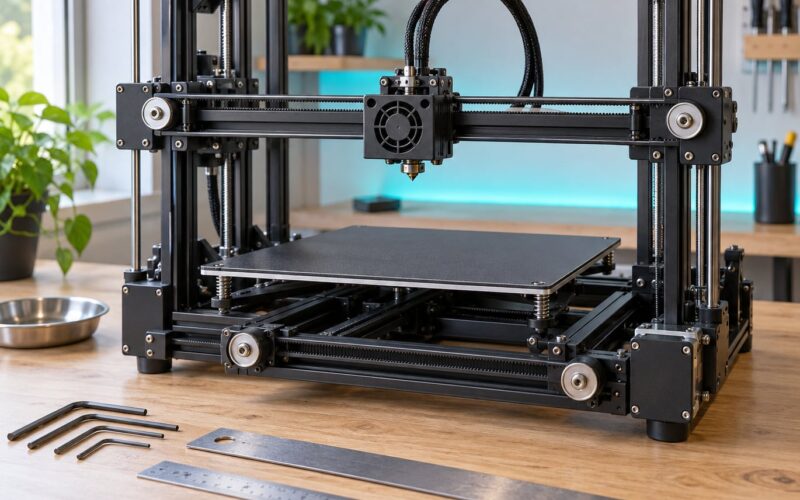
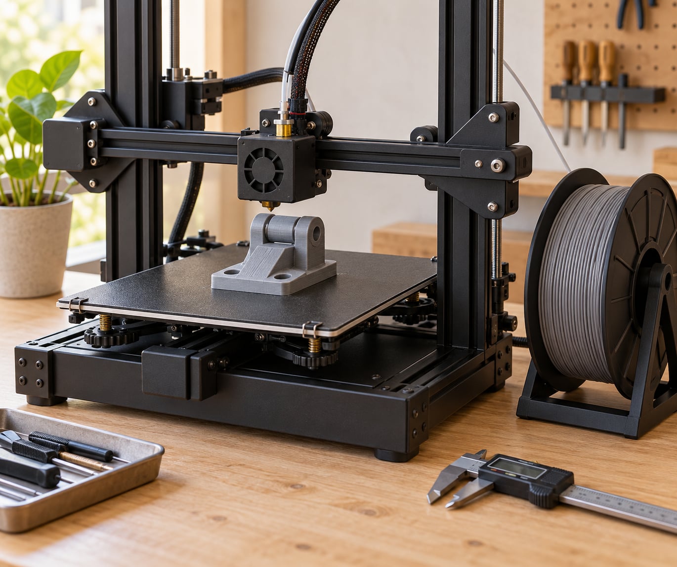
You do not need special hardware. A stock FDM machine with a properly levelled bed and an extruder that can hit 250 mm/s will print a hinge fine.
- A dry spool of filament. Wet filament oozes, and ooze is what bridges a 0.2 mm gap. PLA from a sealed bag is usually fine; PETG needs a dryer box or a food dehydrator.
- A digital caliper. To measure the actual clearance on a downloaded model, and later on your finished print.
- A recent slicer. PrusaSlicer, OrcaSlicer, Bambu Studio or Cura — all four expose the settings that matter here.
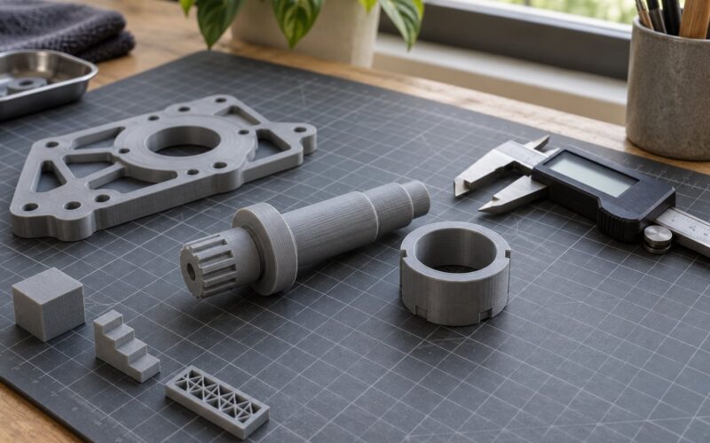
- A test coupon. A printable tolerance ladder with 0.15, 0.20, 0.25 and 0.30 mm steps. Free ones exist on MakerWorld and Printables. Twenty minutes of coupon printing saves a six-hour failed model.
- Optional: brass nozzle. Low flow makes the Z axis rounder and the clearance more predictable. Not essential, but it is the single hardware change that helps most.
Before anything else, run a flow calibration and a first-layer test. If your first layer is thick, your clearance is gone before you start.
Step-by-Step: How to Print Print in Place Hinges Without Fusing
Check the Model and Hinge Clearance
Start with 0.20-0.30 mm of radial clearance per side for PLA, and 0.25-0.35 mm for PETG. Anything tighter and extrusion die swell will close the gap on most printers.
Radial means per side. Diametral means the whole gap across the pin, so 0.50 mm diametral is 0.25 mm on each side. Half the confusion about hinge tolerances comes from mixing these up, so when a model page says “0.4 clearance” check whether it means per side or total.
| Material | Fit | Radial clearance per side | Total diametral gap |
|---|---|---|---|
| PLA | Tight | 0.20 mm | 0.40 mm |
| PLA | Standard | 0.25 mm | 0.50 mm |
| PLA | Loose | 0.30 mm | 0.60 mm |
| PETG | Tight | 0.25 mm | 0.50 mm |
| PETG | Standard | 0.30 mm | 0.60 mm |
| PETG | Loose | 0.35 mm | 0.70 mm |
These are starting points, not constants. Experienced users on the Bambu Lab forum describe 0.1-0.2 mm between pin and hole as workable, and the wider numbers above exist because most consumer printers cannot hold a tighter gap consistently.
If you downloaded the STL rather than designing it, measure it. Slice to G-code, or open the model in your CAD tool and measure across the pin and across the socket. If the gap measures 0.10 mm, that model was designed for a resin printer or a very accurate machine, and it will probably fuse on yours.
Two slicer-side levers can rescue a tight downloaded model without you remodelling it. Bambu Studio, OrcaSlicer and PrusaSlicer expose XY Hole/Contour Compensation — a negative value shrinks holes and contours, which opens the socket up. Cura users set Horizontal Expansion negative for the same effect. Start at -0.05 mm and step down in 0.05 mm increments; go too far and the joint turns into a rattle box.
One caveat on Tinkercad, since it comes up constantly: it cannot make reliable print-in-place clearances. Its shape subtraction gives you a clean circle but no control over fit, and it cannot chamfer an entry edge. If you want to design or edit a hinge, move to Fusion 360, Onshape or FreeCAD. Fusion 360 is free for personal use, which is the usual recommendation on these forums, and a single user parameter named something like “Joint_Clearance” means every joint in a model inherits the same value when you need to change it.
Choose the Orientation
Put the hinge axis vertical, along Z, whenever the geometry allows it. A vertical pin is printed as a series of tiny circles rather than a swept horizontal tube, so it stays round, and a horizontal pin has to bridge across its own length and sags while doing it.
Vertical is also why elephants’ foot matters so much here. The bottom edge of the part is squished by the nozzle, and that squished lip can grow a millimetre wider than the design. A hinge fused only at the base and free everywhere else is the classic symptom.
If the model only works horizontally, look for a teardrop or D-shaped socket. A teardrop profile has a flat at the top that widens as the part rotates, so the joint self-centres and only the narrow point needs a precise fit. It prints without supports and tolerates a lot more dimensional error than a full circle.
Most well-designed hinges need no supports at all. A good download has self-supporting geometry with 45-degree overhangs or better. Never put support material inside the clearance gap — it locks the joint permanently, and support blockers in PrusaSlicer, OrcaSlicer and Bambu Studio only stop supports touching surfaces, not the gap between them.
Set Materials and Temperatures
For PLA, run 200-210 °C on the hot end with a 60 °C bed. For PETG, go 235-245 °C with a 80 °C bed, and dry the filament for four hours at 45-55 °C before loading it.
PETG deserves the extra clearance for a specific reason: it strings. Those thin strands between the pin and the socket behave like reinforcement fibres once they cool, and they weld the joint shut. Reviewers on Reddit describe exactly this in the small gaps inside print-in-place parts. If you must use PETG, print at the high end of the temperature range to cut back on ooze and take the extra 0.05 mm per side.
ABS and ASA work but demand an enclosure and a 0.35 mm per side gap, because warp pulls the socket out of round. For a first hinge, PLA is the right call.
Slice Without Disrupting the Axis
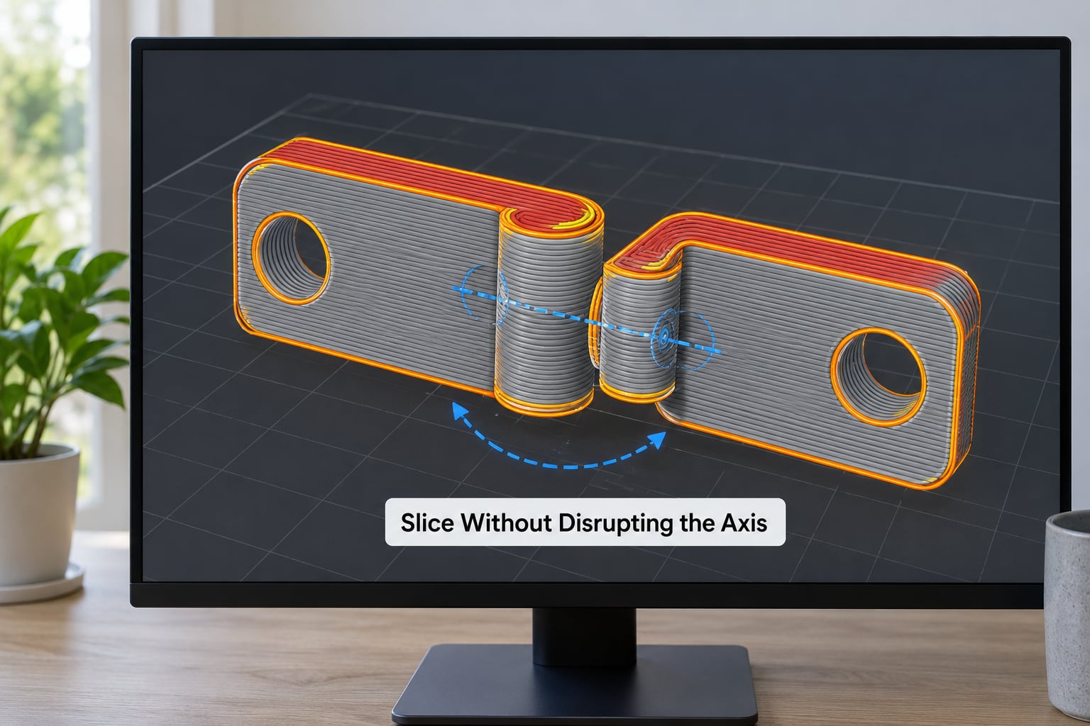
These settings keep the gap open and the pin round. Adjust to your printer, but start here.
| Setting | Value | Why it matters for a hinge |
|---|---|---|
| Layer height | 0.12-0.16 mm | Finer layers resolve the round cross-section better, so the effective gap matches your design clearance |
| Wall generator | Arachne or classic inner-to-outer | Inner-to-outside wall order prints the socket before the pin, tightening the fit |
| Elephant’s foot compensation | 0.15-0.2 mm | Stops the first layer from squishing wider and closing the bottom of the gap |
| Outer wall speed | 40-50 mm/s | Slower outer walls place more accurate perimeters |
| Bridge flow ratio | 0.90-0.95 | Keeps horizontal bridges from sagging into the clearance |
| Bridge cooling fan | 100% | Freezes bridges before they droop |
| Part perimeter walls | 3 | Three walls is enough to keep a pin round without over-constraining it |
| XY Hole/Contour Compensation | 0 to -0.1 mm | Widens holes if the downloaded clearance is too tight |
| Supports inside the joint | None | Support in the gap locks the joint permanently |
Layer height interacts with clearance more than most guides admit. At 0.28 mm layer height, the Z resolution on a round pin is poor and a nominal 0.25 mm gap can close up between layers. Drop to 0.12 mm and the same gap behaves like a gap.
Print, Cool, and Test the Motion
Check bed adhesion before the print starts. A brim that touches the hinge socket can bridge the gap on its own, so keep a 2-3 mm brim-to-object gap or use an adaptive brim.
Let the part cool completely before touching it. PLA becomes noticeably stiffer and more brittle below about 40 °C, and a warm pin will snap if you force it.
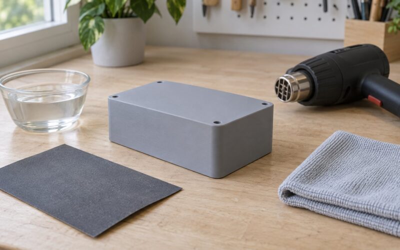
Then work the joint free in small steps. Twist gently, do not pull straight apart — a horizontal pin shears along its layer lines under pure tension. Apply heat with a hairdryer for thirty seconds if it resists, because the plastic is more forgiving warm, and stop the moment you feel the joint give rather than forcing it through.
Test the motion by cycling it twenty times. A hinge that moves smoothly for the first few rotations and then starts catching is sagging bridge geometry, not a clearance problem, and you fix it with bridge settings rather than tolerance.
Common Mistakes
Nearly every failed hinge falls into one of six buckets. Match the symptom, then apply the fix.
| Symptom | Root cause | Fix |
|---|---|---|
| Fused at the base only, free above | Elephant’s foot squishing the first layer outward | Elephant’s foot compensation at 0.2 mm, plus a brim-to-object gap |
| Fused all the way up | Clearance too tight for your accuracy, or wet filament | Dry the filament, re-run flow calibration, set XY Hole/Contour Compensation to -0.05 mm |
| Loose and wobbly | Excessive clearance or an undersized pin | Drop clearance 0.05 mm per side; if you designed it, edit the CAD parameter |
| Pin snaps off | Horizontal pin shearing along layer lines | Reorient the axis to Z, or chamfer the pin so it enters gradually |
| Stiff, grinding motion | Sagging bridges, not clearance | Bridge flow ratio 0.90, 100% bridge cooling, thicker bridge infill |
| Warped or lifted part | ABS or ASA with no enclosure, or a dirty bed | Clean the bed, raise bed temperature, add a brim and an enclosure |
PETG stringing can masquerade as fusion at any height. If the joint is welded by fine hairs rather than a solid wall, no clearance change will help — dry the filament and raise the nozzle temperature instead.
Frequently Asked Questions
Can you print a print-in-place hinge in PLA or PETG?
Yes, and PLA is the easier of the two. PLA gives a more predictable dimension at a 0.20-0.30 mm radial clearance per side. PETG works too, but stringing inside the gap can weld the joint shut, so give it 0.25-0.35 mm per side and dry the filament for four hours before loading it. ABS and ASA also work inside an enclosure, though warping needs an even wider gap.
What layer height is best for a reliable print-in-place hinge?
Between 0.12 and 0.16 mm. Finer layers resolve the round cross-section of a Z-axis pin far better, so the gap you designed actually appears on the print. At 0.28 mm the Z resolution is poor and a nominal 0.25 mm clearance can close between layers. Slowing the outer wall to 40-50 mm/s at the same time gives you noticeably rounder pins.
Why does my print-in-place hinge bind or not move?
If it is fused, the cause is either an elephant’s foot squishing the first layer wider than design or a clearance tighter than your printer can hold. Try 0.2 mm elephant’s foot compensation and XY Hole/Contour Compensation at -0.05 mm. If the joint moves but feels stiff and grinding, the problem is sagging bridge geometry, so fix bridge flow ratio and bridge cooling instead of changing the tolerance.
Do print-in-place hinges need supports?
Good ones do not, because the designer shapes the socket as self-supporting with 45-degree overhangs or a teardrop profile. Always check the model page for a support-free claim before slicing. If the hinge does need supports, keep them away from the clearance gap and use support blockers to stop support material touching the joint. Support material printed into a gap locks the hinge permanently.
How strong should the hinge axis be for repeated movement?
Three perimeters at 0.40 mm width is the usual answer, which leaves the pin solid enough for thousands of cycles in PLA. Strength comes more from how you break the joint free than from the walls: force it gently and along the direction of travel, never straight apart, because a horizontal pin shears along its layer lines. A weak or tapered pin is usually an orientation problem, not a wall-count problem.
How do I fix an STL that is not designed for my printer?
Measure the clearance first with a caliper or in your slicer. If it is under 0.20 mm per side, set XY Hole/Contour Compensation to -0.05 mm in Bambu Studio, OrcaSlicer or PrusaSlicer, or Horizontal Expansion to -0.05 mm in Cura, and step down by 0.05 mm until it moves. If that is not enough, the honest fix is to open the model in Fusion 360, Onshape or FreeCAD and offset the socket surfaces. Tinkercad cannot do this reliably.
Conclusion
Start by measuring. Print a tolerance coupon or check the clearance in a downloaded model with a caliper, and if the gap is under 0.20 mm per side you already know why it will fuse.
Three variables decide the outcome: the clearance in the model, whether the hinge axis runs along Z, and the first layer. Fix those three and how to print print in place hinges becomes unremarkable — dry filament, 0.12-0.16 mm layers, elephant’s foot compensation at 0.2 mm, and no support material anywhere near the gap. Validate all of that on a coupon before committing to a long print.