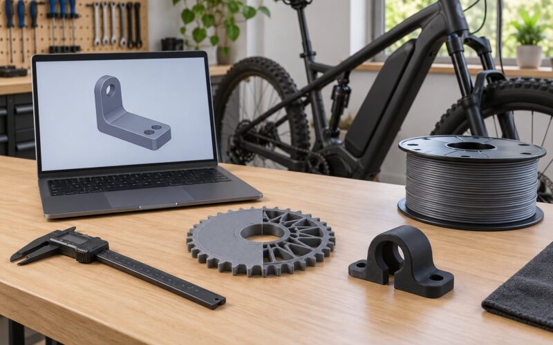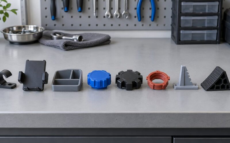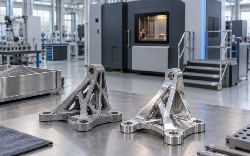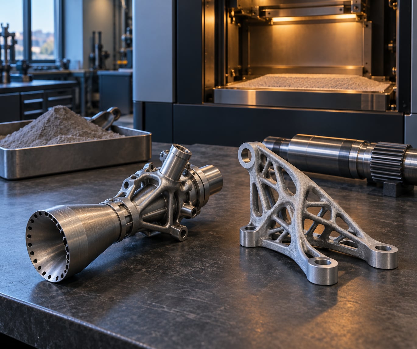
Aerospace uses 3D printed parts — formally, additively manufactured parts — to make the geometry that conventional methods cannot: fuel nozzles with curved internal passages, turbine blades with cooling channels woven right into the metal, airframe brackets with lattice infill, cabin trim, jigs, and replacement spares for aircraft that stopped being built decades ago. Printing wins here because it builds internal shapes layer by layer, trims part counts, and turns a hard geometry into a routine one.
I pulled this together for readers who keep seeing the phrase “3D printed parts” in aerospace coverage and want to know what actually flies. The honest version is more interesting than the marketing version: metal additive manufacturing makes real flight hardware, and the parts that get printed are usually small, hot, or badly shaped for machining, not entire airframes made of plastic.
Below is what gets printed, which process makes it, what material it is made from, and where the whole thing still falls short. If you have a home printer, skip to the section on why a desktop FDM machine is not a shortcut to any of this.
Table of Contents
- What Are 3D Printed Parts in Aerospace?
- How Aerospace Uses 3D Printed Parts in Practice
- How the Parts Move from Design to Production
- Which 3D Printing Processes Are Used?
- Which Materials Are Used for Aerospace-Grade Parts?
- What Are the Main Benefits?
- What Limits and Risks Must Engineers Manage?
- How Are 3D Printed Parts Tested and Approved?
- Will 3D Printing Replace Conventional Aerospace Manufacturing?
- Frequently Asked Questions
- Are 3D printed parts used in real aircraft?
- Can 3D printing make aircraft parts lighter?
- Which materials are most common for 3D printed aerospace parts?
- Are 3D printed aerospace parts certified?
- Is 3D printing cheaper than machining or casting aerospace components?
- Conclusion
What Are 3D Printed Parts in Aerospace?
A 3D printed part is a component built by adding material in thin layers until the solid is complete, guided by a digital model. Nothing is cut away except the raw powder or filament that surrounds it. In aerospace the parts that matter are almost all metal, and the formal name for the whole field is additive manufacturing, standardised into seven process families under ISO/ASTM 52900.
That is the real difference from machining, casting or forging. Subtractive machining starts with a block and removes everything you do not want, so an internal channel means a tool that must enter the part, a possible tool-access problem, and expensive material turning into chips. Additive manufacturing grows the channel instead, which is why a fuel nozzle or a heat exchanger can exist at all in the shape designers want.
Four things follow from that, and they are the entire reason aerospace adopted the process:
- Geometry. Internal passages, conformal cooling, lattices and organic shapes are native to the process, not workarounds.
- Weight. Topology optimisation and lattice infill remove material from where the load path does not need it.
- Part count. A bolted assembly of twenty machined parts can become one printed part with no fasteners.
- Lead time. A digital model can be sent to a qualified machine anywhere, which shortens queues and allows printing on demand instead of ordering against a warehouse.
Everything else in this article is detail hanging off those four points, including the parts of the process that are slow, expensive, and still unresolved.
How Aerospace Uses 3D Printed Parts in Practice
The applications that matter cluster into a handful of categories, and each one suits a different process and material. Reading the table below is the fastest way to understand why aerospace uses 3D printed parts in a very specific set of places rather than everywhere.
| Application | Typical part | Common process | Typical material |
|---|---|---|---|
| Engine hardware | Fuel nozzles, combustor liners, cooling manifolds | Laser powder bed fusion, directed energy deposition | Ni-based superalloy, Ti-6Al-4V |
| Thermal management | Heat exchangers, ducting, manifolds | Laser powder bed fusion, binder jetting | AlSi10Mg, Inconel 625, stainless steel |
| Airframe and structure | Brackets, fittings, seat tracks, stiffeners | Laser powder bed fusion, material extrusion | AlSi10Mg, Ti-6Al-4V |
| Cabin interior | Trim brackets, ducts, handle bases, latch housings | Material extrusion, powder bed fusion | ULTEM, PEEK, Antero 840CN03 |
| Tooling and jigs | Assembly fixtures, drilling jigs, formers, checking gauges | Material extrusion, binder jetting | High-temperature polymer, tooling steel |
| Space and launch hardware | Antenna assemblies, thruster parts, engine injectors | Laser powder bed fusion, electron beam melting | Ti-6Al-4V, Inconel 718, AlSi10Mg |
| MRO and spares | Obsolete brackets, duct segments, trim pieces | Laser powder bed fusion, material extrusion | Matched to the original part’s allow-list |
| Prototyping | Scale models, fit checks, wind tunnel parts | All processes, no qualification required | Cheapest valid option per purpose |
Named programmes matter more than generic claims here, because the numbers below are traceable to public sources. GE Aviation consolidated a fuel nozzle for the LEAP engine from roughly twenty separately manufactured parts into a single additively manufactured one, and reported it as around 25 percent lighter with better durability than the assembly it replaced. That is the canonical aerospace additive manufacturing example and still the one most often cited.
Space hardware follows the same logic with tougher materials. The Aerospace Corporation contributed to the qualification of an additively manufactured omnidirectional antenna assembly for telemetry, tracking and command on a GPS satellite, which is the sort of small, geometrically awkward, low-volume part that printing suits better than a foundry tool. SpaceX has flown printed nickel-alloy combustion chambers in the SuperDraco engine system used on Dragon launch escape hardware.
On the ground, NASA’s most visible prints have been structures and demonstrators rather than flight spares, including a 3D-printed launch pad and habitat concepts for lunar surface study. Tieronjet is the name to remember for regulation: it pushed the first FAA certification of a 3D-printed structural part on a certificated aircraft in the United States, which mattered more than the part itself.
Tooling is the quiet one. Printed jigs, formers, fixtures and drilling templates routinely reach the shop floor faster than machined equivalents, and they cost a fraction of a conventional tool when the tool has to be reworked after a design change.
How the Parts Move from Design to Production
A certified metal part travels through about a dozen steps, and each one exists for a reason. Skipping the middle of this list is how you end up with a part that looks right and fails a fatigue test.
- Requirements and load case. Loads, temperature, vibration spectrum, fatigue life, damage tolerance and the certification level are defined before anyone touches geometry.
- CAD and topology optimisation. The material is allowed to move. Engineers remove low-stress volume and replace it with a designed lattice or rib pattern, then check that the result still carries load in every direction.
- Design for additive manufacturing. The model is rebuilt around the process: build orientation chosen so surfaces land at a good angle, supports designed to come off cleanly, holes and threads pushed to places a machine can reach and a tool can finish.
- Material and process selection. The alloy and the process come off a qualified allow-list. Changing powder supplier or machine type can mean requalification.
- Simulation. Thermal and flow analysis, plus a build simulation that predicts residual stress and distortion before metal is melted.
- Print and support removal. The build runs under in-process monitoring, watching melt pool, temperature and layer geometry rather than just watching for a stopped machine.
- Stress relief and heat treatment. Parts come off the machine needing at least a stress relief, usually followed by a full solution and ageing cycle for alloys that require it.
- Hot isostatic pressing. HIP closes internal porosity and improves fatigue life, which is often the deciding step for safety-critical parts.
- CNC finishing. Bearing seats, sealing faces, threads and datum surfaces get machined. The as-printed surface is rarely good enough for a fit.
- Non-destructive inspection. Computed tomography, radiography and surface inspection, often with witness coupons printed alongside the part.
- Mechanical testing and records. Coupon testing for tensile, fatigue and fracture behaviour, plus a digital record linking powder lot, machine, parameters and operator to the specific part.
Anyone who has watched a printed part distort during stress relief understands step five. The build has to be oriented so the part relaxes into its tolerance rather than out of it.
Which 3D Printing Processes Are Used?
The process you pick determines the size, the alloy, the surface finish and what the part is allowed to do. Aerospace uses a short list of them seriously, and the rest exist mainly as metal prototypes or low-stress hardware.
| Process | Build size | Materials | Finish | Typical aerospace part |
|---|---|---|---|---|
| Laser powder bed fusion (LPBF / SLM) | Medium, roughly a few hundred mm | Titanium, aluminium, nickel superalloys, steels | Rough as printed, needs machining | Engine brackets, ducts, nozzle bodies, structural fittings |
| Electron beam melting (EBM) | Medium, larger than most LPBF | Mostly Ti-6Al-4V | Rougher than LPBF | Implant-style and large titanium frames, prototypes |
| Direct energy deposition (DED) | Large, up to metres | Nickel superalloys, steels, titanium | Good near the deposit | Repair of blades and casings, cladding, large structures |
| Binder jetting | Large, and many parts at once | Sand casting alloys, steels, titanium | Grainy, needs infiltration or sintering | Complex cast patterns, prototype ducts, low-volume hardware |
| Material extrusion (FDM / FGF) | Largest of the practical ones | ULTEM, PEEK, PEI, nylons, composites | Layer lines visible | Cabin trim, ducts, tooling, jigs, covers |
| Vat polymerisation | Small | Resins | Good detail | Patterns and prototypes, not flight hardware |
| Sheet lamination | Very large | Metal or composite sheet | Cut-edge dependent | Masters, models, tooling, not structural flight parts |
Two distinctions matter most in practice. LPBF and EBM are powder-based, so they are excellent detail machines with a small usable envelope; DED is the one that handles large parts and in-field repair because it deposits metal from a feed rather than a bed. And the high-performance polymers are not a lesser class of material — ULTEM and PEEK hold up in cabin environments where an ordinary PLA part would be a liability.
Which Materials Are Used for Aerospace-Grade Parts?
Material choice in aerospace is constrained by temperature, corrosion, fatigue behaviour and what a regulator will accept, not by what a machine can melt. That is why the approved list is short and why substitutes are a real certification event rather than a swap.
| Material | Why it is chosen | Where it flies |
|---|---|---|
| Ti-6Al-4V | High strength-to-weight, excellent fatigue behaviour, good corrosion resistance | Engine-adjacent brackets, ducting, antenna and structural fittings, drone and UAV airframes |
| AlSi10Mg and similar casting alloys | Low density, good castability, mature powder supply | Cabin fittings, heat exchangers, ducting, general airframe hardware |
| Nickel superalloys (Inconel 718, 625) | Creep and oxidation resistance at high temperature | Fuel systems, hot-section parts, thrust structures, nozzle bodies |
| Stainless and maraging steels | Strength, wear resistance, lower cost per part than nickel alloys | Tooling, fasteners, fuel manifolds, some engine fittings |
| ULTEM, PEEK, PEI thermoplastics | Heat and chemical resistance, low outgassing, flame/smoke/toxicity ratings, ESD grades | Cabin interior, ducts, brackets, antenna housings, covers |
| Carbon-fibre composites and filled filaments | Very high stiffness-to-weight, tailorability | UAV structures, fairings, tooling, trim |
For polymers, the specification is about behaviour in a pressurised cabin as much as strength. Outgassing, flame, smoke and toxicity ratings, and electrostatic discharge protection for electronics-adjacent parts are requirements written into the drawing, and material that lacks them cannot go in the cabin regardless of how well it prints.
Practitioners on additive manufacturing forums make the same point from the other side: the question is never “can this metal be printed” but “which approved material and process is on the list for this part.”
What Are the Main Benefits?
The benefits are real, and they are narrower than the hype suggests. Here is what an aerospace team actually gets, in the order that usually decides the business case.
- Lighter geometry. Topology optimisation and lattices remove material away from the load path. Teams commonly report weight savings in the 20 to 30 percent range for redesigned brackets and fittings rather than for whole structures.
- Fewer assembled parts. Consolidation of twenty-part assemblies into one printed body is where fastener count, leak paths and assembly labour all drop at once.
- Faster iteration. Changing a bracket no longer means re-cutting a fixture. A design tweak ships to the machine in hours rather than a queue of weeks.
- Faster tooling. Jigs, formers and fixtures are the classic quick win, because the tooling does not need flight certification and the payback arrives in weeks.
- Lower material waste. Powder can often be reused, and near-net-shape deposition wastes far less metal than machining a solid block down to a thin bracket.
- Shorter lead times. Queue time drops because the part starts as data. Real gains depend on the post-processing steps, which is where the schedule usually slips.
- On-demand and localised production. A spare can be produced where the aircraft is instead of shipped from a central warehouse, and obsolete parts can be made years after production ends.
- Simpler maintenance. Consolidated parts have fewer interfaces, fewer fasteners and fewer places for a crack to start.
Cost follows from all of that rather than from a cheaper machine. The metal is not cheap, the qualification is expensive, and the per-part number only looks good at low to medium volume.
What Limits and Risks Must Engineers Manage?
Additive manufacturing competes with machining, not with magic. Engineers managing the risk are really managing a fixed list of known weaknesses, each of which has a known mitigation.
- Surface roughness and tolerance. As-printed surfaces need machining for any sealing or bearing function, so tolerances have to be designed rather than assumed.
- Anisotropy. Layer interfaces can behave differently from the bulk material, so test data must come from the orientation and location the part will actually be built in.
- Porosity and lack of fusion. Incomplete bonding between layers shows up as defects, which is why HIP and inspection are standard rather than optional.
- Residual stress and distortion. Parts can move during stress relief, and the distortion is not always recoverable afterwards.
- Fatigue life. Fatigue, not static strength, is what limits printed metals, and qualification data has to be generated for the specific process and orientation.
- Repeatability and scale-up. A process qualified on one machine, one powder lot and one build volume does not automatically transfer to another.
- Inspection difficulty. Internal defects in complex geometry are hard to characterise, which pushes NDT capability and digital records up the schedule.
- Post-processing burden. Support removal, heat treatment, HIP, machining and finishing add cost and calendar time after the build ends.
- Size and throughput. Very large structural parts exceed most metal machine envelopes, and build rate limits how many parts a year a shop can actually deliver.
- Cost of qualification. The engineering hours for process qualification and material data exceed the machine time for small parts. That is why printed tooling pays back far sooner than printed flight hardware.
And the one people in forums argue about most: a desktop FDM machine is not a path to flight hardware. Makers on homebuilder forums generally accept that printed parts on an experimental aircraft can be legitimate when the owner is involved and accepted data supports the process, which is a different thing from a certified part on a transport aircraft. Owner-produced parts also carry a weight and inspection burden the owner has to carry, and the regulatory grey area for light aircraft is real.
How Are 3D Printed Parts Tested and Approved?
A 3D printed part is approved the same way any other part is approved: by evidence that it was built to a qualified process and meets the design’s requirements. What changes with printing is how much evidence has to be generated first.
The pathway usually runs in four steps. First, the material and process are qualified at the supplier level, with documented powder chemistry, machine parameters and mechanical property data from test articles. Second, the part design and its material are entered onto an allow-list for that aircraft or engine programme, which is what stops a part being made on a process nobody vouched for. Third, each production part is built under in-process monitoring, inspected non-destructively, and compared against the qualification data. Fourth, the build record is filed: powder lot, machine, operator, parameters, NDT results and certificates, linked to the part’s serial number for the life of the aircraft.
Test evidence usually combines several sources. Coupon testing pulls mechanical properties, including fatigue, from test articles printed alongside production parts. Computed tomography and radiography catch internal voids and lack of fusion. Surface inspection and dimensional checks cover the machined features, and each mechanism covers a different failure mode rather than repeating the same one.
The tier matters more than the technology. Prototypes need nothing but a valid model. Tooling needs durability and dimensional repeatability. Cabin and non-structural parts sit in the middle. Engine hot sections, primary structure and flight controls carry the full burden of qualification, and there is a long history of a part type earning its way up that ladder slowly.
Regulators differ in approach. European practice has leaned toward self-certification by the organisation under an approved production system, and the certification of 3D printed metal parts on aircraft in Europe has generally followed that route. The United States has required FAA approval for each specific part, which is slower and is why the Tieronjet certification and the FAA’s additive manufacturing roadmap are the reference points people cite. Quality management systems such as AS9100 sit underneath all of it, and they govern the records, suppliers and corrective action rather than the part’s strength directly.
Will 3D Printing Replace Conventional Aerospace Manufacturing?
Not as a replacement, as a hybrid. Casting, forging and machining remain cheaper per part at volume, hold better fatigue data at scale, and work on large structural components that do not fit a build chamber. Those processes are not going anywhere.
What is growing is the share of parts where geometry decides the process. A fuel nozzle with internal passages, a bracket that saves 30 percent of its weight, a thermal exchanger, a low-volume satellite antenna, an obsolete spare that no supplier will quote any more — those are printed, and they will keep being printed because no other method reaches them.
Three developments will push the share higher. Certification of new materials and processes is unlocking parts that are currently outside the allow-lists. In-space manufacturing moves from demonstration toward logistics, where a part made in orbit removes launch mass and resupply demand. Closer to the shop floor, in-process monitoring is turning printing from an open-loop process into something that can catch a defect while the layer is still being laid, which is what certification of volume production needs.
Redesign is the quiet lever. A printed part is not a machined part with a new shape; it is a part designed around what the process does well, and those parts can be half the mass of what they replace. As of 2026, the limiting factor is less the machine and more how long a material takes to work through qualification.
Frequently Asked Questions
Are 3D printed parts used in real aircraft?
Yes, though not in the way the marketing suggests. Additively manufactured metal parts fly in engines, cabin interiors, thermal systems, and structural fittings on certificated aircraft from several manufacturers. The best-known example is GE Aviation’s fuel nozzle for the LEAP engine, which consolidated roughly twenty parts into one. Most production use is small, hot, or geometrically awkward hardware rather than large airframe structures.
Can 3D printing make aircraft parts lighter?
Often, yes, but by a different route than people expect. Engineers do not simply scale a part down; they remove material away from the load path using topology optimisation and replace it with designed ribs or lattices. Redesigned brackets and fittings commonly land in the 20 to 30 percent weight saving range. Savings on large structural parts are harder to achieve because those are limited by build size and fatigue data.
Which materials are most common for 3D printed aerospace parts?
Titanium Ti-6Al-4V and aluminium casting alloys such as AlSi10Mg cover most airframe, ducting and bracket work. Nickel superalloys including Inconel 718 and 625 handle hot-section and fuel-system parts where creep and oxidation resistance matter. Cabin interiors use high-temperature thermoplastics such as ULTEM and PEEK for their low outgassing and flame, smoke and toxicity ratings.
Are 3D printed aerospace parts certified?
Yes, through a defined qualification process rather than a one-time approval of the technology. Material and process are qualified at the supplier, the design and material are added to a programme allow-list, each part is built under in-process monitoring and inspected, and the build record is filed against the serial number. Prototypes and tooling need far less than this; engine hot sections and primary structure need the most.
Is 3D printing cheaper than machining or casting aerospace components?
It depends on volume, and the crossover is usually low to medium production. Printing wins on small parts, complex internal geometry, and low quantities where tooling or patterns for casting would dominate the cost. Machining and casting win on high-volume, simple, large parts, and printing carries extra cost for heat treatment, hot isostatic pressing, CNC finishing and process qualification that rarely appears in the headline comparison.
Conclusion
Additive manufacturing earns its place in aerospace wherever geometry is the problem: internal passages in fuel and cooling hardware, consolidated assemblies, topology-optimised brackets, low-volume space hardware, obsolete spares, and the tooling that builds all of it. The processes are chosen per application, the materials come from a short qualified list, and the certification burden scales with how close a part sits to the engine or the primary structure.
Start with the part, not the printer. Define the loads, temperature, geometry, material constraint, inspection requirement and certification level, and the right process usually names itself. If your machine cannot hold the tolerance and the alloy is not on the list, machining is still the right answer — and knowing that early is cheaper than finding it out after the first build.