Metal 3D printing post processing steps run in a fixed order: depowder the as-built part, take it off the plate, strip supports and gates, stress relieve and clean, machine or finish the features that need tolerances, then inspect and document. Skipping a step or reordering them is the usual reason a part arrives functional on the bench and unusable in assembly.
The order matters because each operation makes the next one possible or harder. You cannot machine a feature accurately while residual stress is still pulling the part out of shape, and you cannot blast a surface that later needs to stay at a controlled roughness. The total route is where most of the lead time hides, and it is where most of the surprises come from.
Below is the workflow I would follow for a typical metal additively manufactured part, step by step, with the checks that tell you whether each stage actually worked.
Table of Contents
- What You Need
- Metal 3D Printing Post Processing Steps: Step by Step
- 1. Confirm the Printing Process and Material
- 2. Inspect the Part Before Post Processing
- 3. Remove the Part from the Build Platform
- 4. Remove Supports and Gate Material
- 5. Relieve Residual Stress and Clean the Surface
- 6. Machine or Finish Critical Features
- 7. Inspect and Verify the Finished Part
- 8. Prepare the Part for Use or Further Assembly
- Common Metal Post-Processing Mistakes
- Post-Processing Tips for Better Results
- Frequently Asked Questions
- Can you machine metal 3D printed parts?
- What is the usual order of metal 3D printing post processing steps?
- Is stress relief required for every metal 3D printed part?
- What is the best way to remove supports from a metal part?
- How do you clean a metal 3D printed part without damaging it?
- When is machining necessary after metal 3D printing?
- Conclusion
What You Need
Before you touch a part, gather the information and equipment the route will demand. Most failed post-processing jobs trace back to a decision made before the part ever left the printer.
- Process and material data: the printer family, the alloy, and the supplier’s specification sheet. Alloys differ in temper, shrinkage, and which treatments are safe.
- Build information: the orientation the part was printed in and where the supports and gate were placed. Support scars show up later on mating faces if you did not know where to look.
- Separation tools: band saw, cut-off wheel, wire EDM, or a deburring tool, plus files and deburring stones for the gate residue.
- Heat treatment access: a vacuum furnace or an outsourced heat treater with a documented process. Contact with air at temperature is what causes oxidation and scaling on steels and titanium.
- Cleaning and finishing equipment: a blasting cabinet with glass bead or alumina, an ultrasonic cleaner, and the chemistry matched to the alloy, such as pickling solution for stainless steel.
- Metrology: calipers and micrometers for a first look, a surface finish comparator or profilometer for roughness, and access to a CMM or coordinate measuring machine when tolerances are tight.
- Non-destructive inspection: CT scanning for internal channels, and dye penetrant or dye-free leak testing for sealed parts.
- Personal protective equipment: eye and face protection, cut-resistant gloves, a suitable respirator for powder handling, and ventilation for chemical cleaning.
Metal powder is the reason several of those items are not optional. Fine powder and its bound residues are respiratory hazards, and blasting media carries silica unless certified non-silica.
Metal 3D Printing Post Processing Steps: Step by Step
1. Confirm the Printing Process and Material
Start by identifying whether the part came from powder bed fusion, directed energy deposition, binder jetting, or metal extrusion, because each process arrives with a different set of problems. This determines the whole route before any tool is picked up.
Powder bed fusion (SLM, DMLS, LPBF) parts are nearly solid but carry coarse, layered surfaces, high residual stress, and attached supports. Binder jetting (MBJ) parts arrive as a loosely sintered “green part” that is fragile, oversized, and full of uncured binder. Directed energy deposition (DED) parts come off the plate with comparatively little support, good dimensional accuracy, and heat-affected zones. Metal extrusion (MEX) parts are a green body that needs debinding and a full sinter cycle, closer to powder metallurgy than to welding.
Record the alloy and its temper target, not just the alloy name. Ti-6Al-4V, 316L, 17-4PH, AlSi10Mg, and Inconel 718 each have their own stress relief, solution, aging, and passivation routes. Where a supplier publishes a recommended route, follow it. A service bureau’s specification reflects the parameters their machines actually ran, and deviating from it is how parts crack during stress relief.
2. Inspect the Part Before Post Processing
Record the as-built condition before any destructive operation, because this is your only baseline for deciding what finishing a part actually needs. Photograph every face, mark the part number and orientation on the drawing, and note where supports were attached.
Look for powder on horizontal down-facing surfaces, visible support contact marks, delamination or lack-of-fusion indications on curved or near-vertical walls, spatter on DED parts, and any edge damage from handling. Then take a few critical dimensions. As-built LPBF parts typically hold general tolerances around 0.1 to 0.2 mm, which is fine for a fixture body and useless for a bore that has to slip onto a shaft.
That measurement does one job: it tells you how much stock to leave for machining. Overestimating leaves material you will grind off later, and underestimating means discovering you cannot reach tolerance because the feature is already undersize.
3. Remove the Part from the Build Platform
Get the part off the plate without shocking it, because thin walls and unsupported overhangs are at their most fragile in the as-built condition. A plate that flexes, or a part levered from one corner, can snap a feature the printer did perfectly.
The usual sequence is a manual snap-off for simple, robust parts on a mechanically retained plate, then a light band saw or cut-off wheel pass for heavier parts and thick plates. Wire EDM gives the cleanest result where heat-affected zones near a thin rim are unacceptable, because it cuts without a thermal footprint. Abrasive water jet cutting works well on large plates and keeps the part cool, though the cut edge quality needs finishing.
Control three things during separation: heat at the cut, impact at the parting line, and contamination. Let the plate cool to room temperature first if the part was just built, support the part on a soft surface, and never lever against a functional face. If the design includes small tabs or a sacrificial break line, wire it deliberately rather than bending until it snaps.
4. Remove Supports and Gate Material
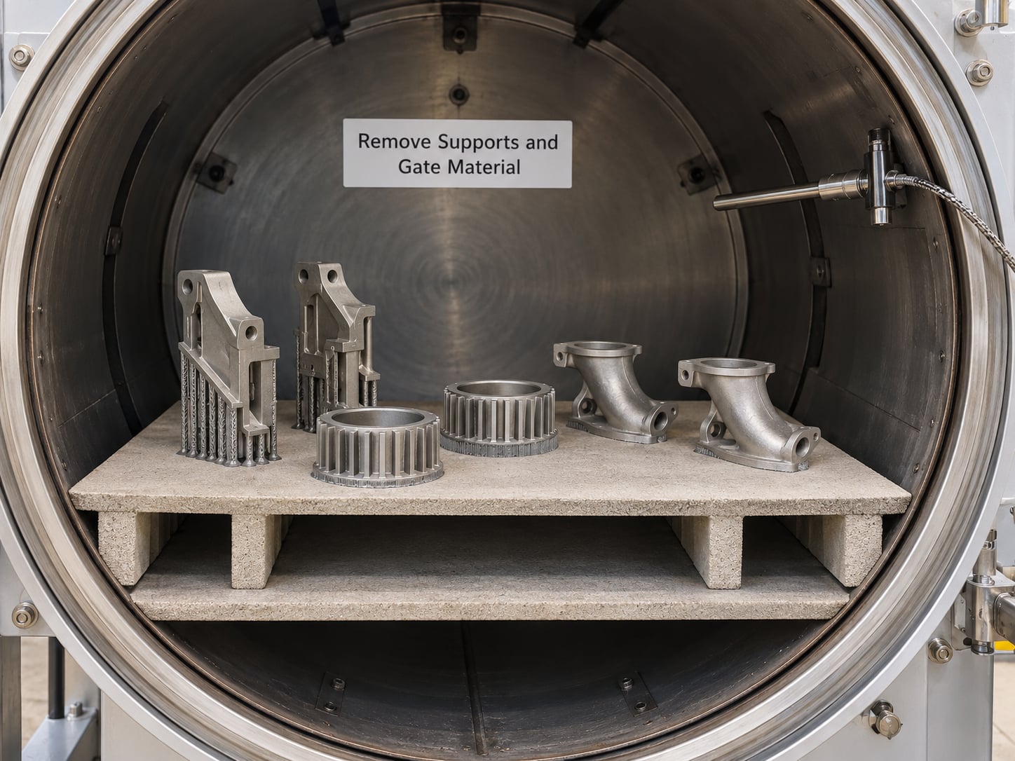
Cut supports off in stages and take thin slivers rather than trying to snap a whole branch in one movement. Whether that is a band saw, a hand file, a wire EDM, or a carbide deburring blade depends on how thin the feature you are uncovering is. Support removal on deep internal channels is still the hardest manual job in the sequence, and it is the step most often outsourced.
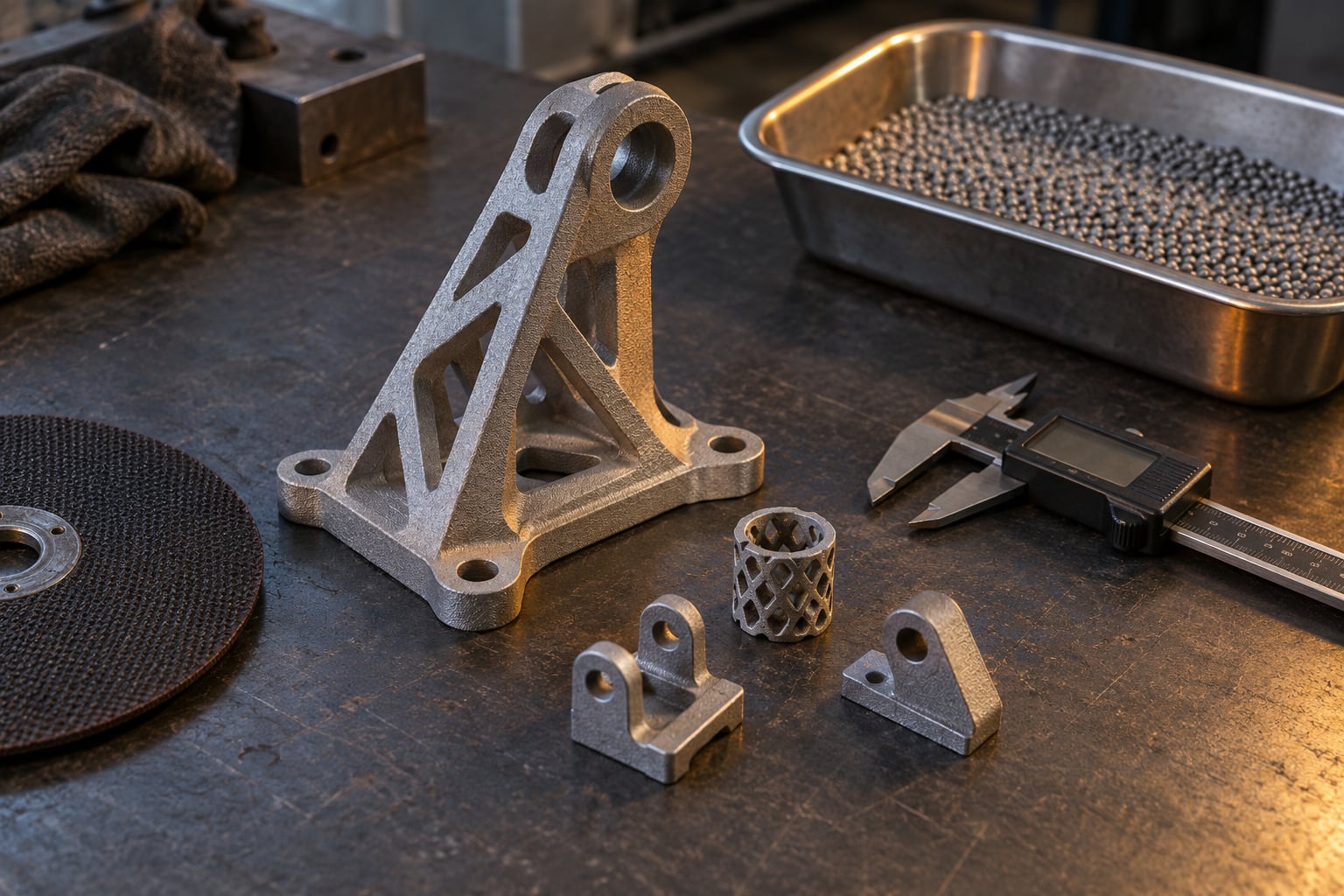
Work from the outermost supports inward, supporting the part continuously on a fixture or sacrificial stand so the weight of the piece never loads the surface you are cleaning. Flush cutters and carbide burrs handle the roots where blade access is tight. A support scar, or “scallop”, is a shallow depression left where metal met support; on a functional surface it is a stress concentrator and it has to be blended, not left.
Keep an eye on the geometry while you work. A part that distorts during support removal, twists on the bench, or no longer lies flat has moved, and the rest of the route will be chasing that error the whole way through. Where internal channels were printed, flush out loose powder as you go; trapped powder in a closed volume is effectively permanent and can force a scrapping decision much later.
5. Relieve Residual Stress and Clean the Surface
Stress relief comes before machining because heat is the cheapest moment to fix a warped part. Rapid solidification in metal AM leaves high tensile residual stress, and a part machined while still stressed will move as the stress releases. Stress relief is not optional for load-bearing or fatigue-critical work.
Typical routes, all of which you should confirm against the supplier’s specification for the exact alloy and temper:
| Alloy | Typical treatment | Approximate conditions | What it buys you |
|---|---|---|---|
| Ti-6Al-4V (ELI) | Stress relief or anneal | 550 to 600 C for stress relief, 700 to 800 C for anneal, hours at temperature, controlled cooling | Dimensional stability, ductility, lower distortion before machining |
| 316L stainless | Solution anneal | around 1000 to 1100 C, fast cool | Corrosion resistance restored after welding or HIP |
| 17-4PH | Solution treat then age | roughly 1050 C solution, then aging in the H900 to H1150 range depending on target strength | Very high strength with good machinability in the aged condition |
| AlSi10Mg | Solution treat and age (T6) | roughly 530 C solution, then artificial aging | Strength and fatigue life over as-built T0 |
| Inconel 718 | Solution plus precipitation age | around 950 to 1000 C solution, then 700 C aging for several hours | Aged strength for high-temperature service |
| CoCr / dental alloys | Anneal or stress relieve, per spec | process specific | Dimensional stability for fitted restorations |
Hot isostatic pressing is the next step up. It is not heat treatment exactly, but it closes internal porosity and gas voids under high-pressure argon, improving fatigue life on parts that will see cyclic loading. It is expensive, adds days, and changes dimensions slightly, so it belongs before final machining and usually after rough machining where it matters most.
Plan for distortion. Anything with thin walls, long unsupported spans, or a large flat face can warp on the way up or on the way down. Support the part on high-temperature setters or graphite tooling, keep fixturing marks away from functional surfaces, and above all stay inside the temperature ramp the supplier specified. For warped parts, a pre-machining straightening pass under control is far cheaper than discovering bow after finishing.
Cleaning follows. Loose powder comes off with compressed air, a brush, or a vibration-cleaning cycle, followed by ultrasonic cleaning to shift what is trapped in surface texture. Abrasive blasting with glass bead or alumina gives a uniform matte surface and takes the edge peaks off layered surfaces; media hardness should stay well below the alloy hardness so you are not embedding contamination. Pickling and chemical etching remove oxide scale, and passivation restores the passive chromium oxide film on stainless and cobalt-chrome parts. Whatever you use, check compatibility: pickling chemistry that is right for 316L is wrong for titanium and will etch it.
For binder jetted parts, the order is different. The body gets a controlled debind cycle, then sintering, which is where the 15 to 20 percent shrinkage allowance lives. Design in that compensation or the part will not meet size after the furnace.
6. Machine or Finish Critical Features
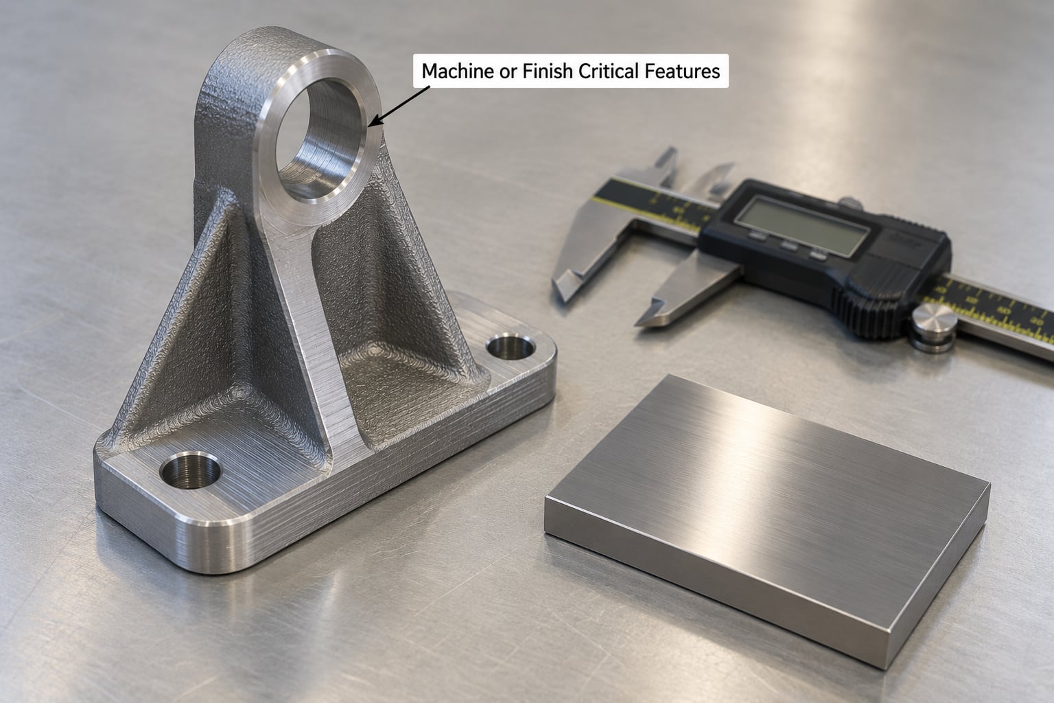
Machine whatever the design promised and the printer cannot hold: bores, threads, sealing faces, bearing seats, and gauging surfaces. LPBF is routinely held to roughly 0.1 to 0.2 mm as printed, so a tolerance that matters functionally usually means a finishing operation.
Plan a machining allowance rather than chasing zero. Leaving on the order of 0.5 to 1 mm of stock on machined features is common practice for metal AM, and it exists so the machine has material to cut and a consistent load to establish a true datum. The trade is time: more stock means a longer, more expensive cut, less stock means risk on features that print undersize. Some shops work down to a thinner stock and hold more time for finishing.
CNC milling handles pockets and flat faces, CNC turning handles round parts, and wire EDM or grinding handles tight holes and hardened features where a cutter would break. Leave the setup thinking: where is the datum, and does the fixture reach the tool? Fixturing on a printed surface without a machined pad leaves witness marks and eats tolerance. Threads are usually cut rather than printed, and printed threads suit light duty only, which is a question that comes up constantly on machining forums.
Surface finishing is a separate decision from dimensional machining. The method you choose sets the roughness you will end up with, and the method you need depends on the alloy and the function of the surface.
| Method | Typical Ra outcome | Good for | Watch out for |
|---|---|---|---|
| As-printed LPBF | roughly 6 to 15 micrometers | Fit checks, non-critical prototypes | Layer lines, trapped powder |
| Glass bead or alumina blasting | roughly 1 to 3 micrometers | Uniform matte finish, cleaning | Media embedment, loss of detail on sharp edges |
| Vibratory or barrel finishing | roughly 0.5 to 2 micrometers | Many small parts with no tight features | Part-to-part variation, damage to small features, and it is hard to control per-part uniformity |
| Precision grinding | roughly 0.2 to 0.8 micrometers | Flatness and size on sealing faces | Heat, cost, material removal |
| Manual or buff polishing | roughly 0.1 to 0.5 micrometers | Appearance, low-wear faces | Hours of labor, inconsistent between operators |
| Electropolishing | roughly 0.1 to 1 micrometer | Corrosion resistance, biocompatible surfaces, complex geometry | Cost, hydrogen embrittlement risk on high-strength steels, and it smooths but does not flatten |
Electropolishing is worth calling out because it is often the right answer for internal channels and complex geometry. It removes material rather than dragging it across the surface, so it preserves sharp edges and reaches into features that mechanical tools cannot. The trade is that it corrects roughness, not form: if a bore is out of round, polish it and it stays out of round.
Surface protection comes after finishing where the service demands it. Passivation on stainless and CoCr, anodizing on aluminum alloys, PVD or DLC coatings for wear, and thermal spray for restore-on-wear surfaces. The order is not flexible: coatings follow blasting and machining, and passivation follows any operation that exposes fresh metal, including machining.
7. Inspect and Verify the Finished Part
Verify against the drawing, in the order that costs the least to fail early. Visual and tactile first: look for burrs, residual support scallops, blast media embedded in the surface, tool witness marks on cosmetic areas, and any indication of a crack at a support root.
Dimensional verification comes next, with a coordinate measuring machine for tight tolerances and calipers or micrometers where the drawing is looser. Check the features you machined, plus the overall envelope, because heat treatment and finishing both move geometry. Note the actual surface roughness with a comparator or profilometer rather than trusting the process name.
Internal features are where problems hide. CT scanning gives a non-destructive view of internal channels, lattice structures, and the interface between a machined bore and printed material around it, and it is becoming standard practice for complex fluid and cooling parts. Where the part must hold pressure or fluid, dye penetrant testing on non-porous alloys or a pressure or flow test proves the function directly. For regulated work, first article inspection to AS9102 documents every characteristic on the drawing, and materials certificates for the powder or the finished part close the traceability loop.
8. Prepare the Part for Use or Further Assembly
Finish the last mile so the part arrives at assembly ready. That means a final cleaning pass after all handling, lubrication where the design calls for it, marking for traceability, and the documentation packet: heat treatment charts, inspection results, and the material certificate.
Storage matters more than most people expect. Parts with machined surfaces that will sit for weeks before use can pick up moisture and staining, and a titanium or passivated stainless part touching dissimilar metal in a drawer can show galvanic marking. Vented, non-abrasive packaging and a short quarantine between finishing and assembly keep the surface you paid to finish intact.
Common Metal Post-Processing Mistakes
Aggressive machining on an unstressed, unproven part is the most expensive error. Cutting into a printed wall with a light, interrupted load invites delamination along the layer interface, and a part that cracks at the machine is a scrapped part plus a scrapped billet. Prove the route on a sample of the same geometry before running production.
Using the wrong abrasive or chemistry comes next. Silica-containing media leaves a residue that is a nightmare to remove, alumina at the wrong hardness can erode a thin printed wall, and pickling chemistry meant for stainless will etch titanium. Match the media and the chemistry to the alloy, and test on a coupon.
Skipping stress relief to save a few days trades a real property improvement for a schedule. Residual stress shows up later as a part that moved after machining, or as a fatigue crack in service, which is a far more expensive place to discover it. Measuring before the part has cooled to room temperature wastes the measurement and can send you machining a still-moving part.
Contamination gets introduced at every stage that touches the part. A nitrile glove fingerprint before a passivation step, blast media left in a channel, and a dirty fixture that transfers ferrous particles onto stainless all end up as corrosion sites. Handle clean, use dedicated non-ferrous tools on stainless, and clean again at the end.
Post-Processing Tips for Better Results
Plan the metal 3D printing post processing route at design review, not at the finishing bench. Support placement, gate location, powder evacuation openings, and machining stock are all decisions made in CAD, and they determine how much hand work the part will need. A design-stage review of support access on complex internal channels saves more time than any equipment choice.
Record every operation as you go: parameters, fixtures, operators, dates. When a nonconformance shows up three operations later, that record is the difference between a targeted fix and a full re-run, and it is what an auditor or a customer quality review will ask for.
Start with conservative parameters on the first part of a new geometry. Higher feed, higher blast pressure, and longer pickling time all make faster progress until the first time they don’t, and the failure tends to be uninspectable until much later. A slower first article is cheap information.
Protect cosmetic surfaces. If a face matters for appearance, mask it or use fixturing that contacts only sacrificial areas, because there is no way to blend a tool witness mark out of a visible surface convincingly. Decide which surfaces are cosmetic before the first operation, not after the first scratch.
Match verification to the actual requirement. Surface finish targets should be written as a Ra value with a measurement method, tolerances should name a standard, and any certification requirement, from AS9102 to a biocompatibility surface, should be settled before the print job is released rather than after the part is finished.
Frequently Asked Questions
Can you machine metal 3D printed parts?
Yes. Metal AM is routinely machined on CNC mills and lathes, and for functional parts it usually is. Bores, threads, sealing faces, and bearing seats are cut after printing because as-built tolerances of roughly 0.1 to 0.2 mm are too loose for a slip fit. Leave a machining allowance of roughly 0.5 to 1 mm on those features so the cutter has consistent material to remove.
What is the usual order of metal 3D printing post processing steps?
The usual order is: depower, remove the part from the build plate, strip supports and gates, stress relieve, clean, machine critical features, finish surfaces, inspect, then protect and document. Machining comes after stress relief because a part still holding residual stress will move as the stress releases. Surface protection comes last, after any operation that exposes fresh metal.
Is stress relief required for every metal 3D printed part?
Not every part, but every part that is machined, dimensionally critical, or fatigue loaded. Stress relief is what keeps a part from warping after machining and what reduces crack initiation in service. A cosmetic prototype in a non-critical material can sometimes skip it, which is why the decision belongs with the person who specified the part’s use, not with the finishing bench.
What is the best way to remove supports from a metal part?
Cut supports off in stages with a band saw, wire EDM, or carbide flush cutters, taking thin slices instead of snapping branches off. Support the part continuously so its weight never loads the surface you are cleaning, and work inward from the outermost supports. Wire EDM is the cleanest option near thin walls because it cuts without a heat-affected zone.
How do you clean a metal 3D printed part without damaging it?
Start with loose powder removal using compressed air, brushing, or vibration cleaning, then use an ultrasonic bath for what sits in surface texture. Abrasive blasting with glass bead or non-silica media gives a uniform finish without embedding contaminants. Match pickling chemistry to the alloy, and treat titanium and aluminum with their own compatible processes rather than stainless steel chemistry.
When is machining necessary after metal 3D printing?
Machining is necessary wherever the printed surface must hit a tolerance, a fit, or a sealing condition that printing cannot hold: bores, threads, datum pads, flanges, and gauge features. It is also useful for creating clean fixturing points. Cosmetic or purely functional-as-printed surfaces, such as a lattice or a flow channel that will be deburred rather than gauged, usually do not need it.
Conclusion
Start with three things: identify the alloy and printing process, inspect the raw part and record a dimensional baseline, then build the route from the part’s geometry, tolerances, and end use. Everything after that is execution. The shops that finish quickly are rarely the ones with the fastest machines; they are the ones that decided, before printing, where supports went, what stock to leave, and which surface actually has to be smooth.