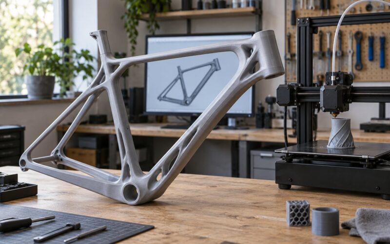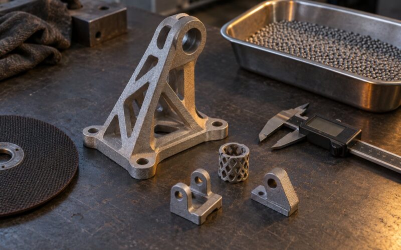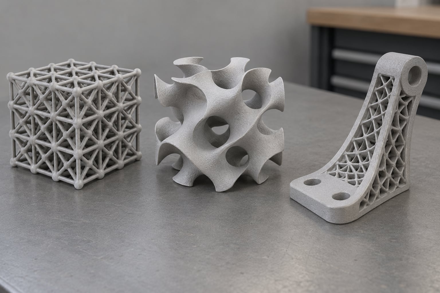
A lattice structure in 3D printing is a connected network of thin struts and nodes that replaces a part’s solid interior, so material only sits where it carries load. Printed lattice structures are lighter than solid parts while staying stiff or strong enough for the job, and additive manufacturing is what makes those internal networks practical to build.
The idea is not new. Honeycombs, spider webs, bone and lobster shells all solve the same problem: how to be stiff without being heavy. What changed is manufacturing. A few years ago, generating a lattice meant industrial simulation software and a metal powder machine. Today a free mesh tool can put one inside your own model and a desktop printer can make it in an afternoon.
This guide covers what lattices actually do mechanically, the main families you will run into, how to generate them, and the print settings that decide whether the part comes out strong or falls apart in your hands. Last updated for 2026, and it assumes you have sliced a part before but have never designed one for load.
Key takeaways
- A lattice replaces solid material with a repeating network of struts, cut weight where the load path does not need it.
- Relative density, strut thickness and cell orientation control stiffness, strength and energy absorption more than the material choice does.
- Strut, planar, TPMS and surface-based lattices behave differently, and each fails in a different way.
- Most processes demand a minimum member thickness. Below it, you get fragile, faceted features or trapped powder.
- Free tools exist. Blender, FreeCAD and Grasshopper all generate lattices; commercial engines are faster but not required.
Table of Contents
- What Are Lattice Structures in 3D Printing?
- How Do Lattice Structures Work?
- What Are the Main Types of 3D-Printed Lattices?
- How lattice structures differ from ordinary infill
- Where Are Lattice Structures Used?
- How Do You Design a Lattice for 3D Printing?
- What Unit Cell Should You Choose?
- Which 3D Printing Process Works Best?
- What Print Settings and Slicing Parameters Matter?
- What Are the Advantages and Limitations?
- How Do You Test and Validate a Lattice Part?
- Frequently Asked Questions
- Are lattice structures stronger than solid 3D-printed parts?
- Can you 3D print lattice structures without supports?
- Are lattices the same thing as infill patterns?
- Which 3D printers can manufacture lattice structures?
- Are lattice structures reliable enough for production use?
- Conclusion
What Are Lattice Structures in 3D Printing?
A lattice structure is a three-dimensional network of connected struts and nodes, built from a repeating unit cell, that replaces the solid interior of a part. By controlling how much material sits inside the shape, you get a part that is far lighter than a solid one while keeping stiffness, strength or energy absorption where the load actually needs it.
The word gets used loosely, so it is worth being clear about what is and is not a lattice here. A slicer’s infill setting is not a lattice structure in the engineering sense. Infill is a fill pattern inside a solid shell, chosen for speed or surface texture. A lattice structure is a deliberately designed internal geometry with its own mechanical behaviour, generated from parameters like relative density and cell type rather than picked from a dropdown of patterns.
One more disambiguation, since the term is polysemous. In materials science, a “lattice” also means the repeating atomic arrangement in a crystal, and a crystalline lattice describes molecular order. That is a different concept from the mechanical lattice used in additive manufacturing, which is macroscopic geometry on the millimetre scale.
How Do Lattice Structures Work?
A lattice works like a miniature truss bridge. Load enters the part through its outer skin, travels into the struts, and crosses to the opposite side through the network. Bulk material that would sit in the middle contributes almost nothing to that path, so removing it costs little stiffness and saves most of the mass.
Compare an office chair seat. A solid shell is strong everywhere and heavy everywhere. A lattice seat keeps a continuous rigid skin, then puts a graded lattice core beneath it: dense under the load path where someone sits, sparse toward the edges. The rider feels the same support while the seat uses a fraction of the material.
Aerospace panels use the same logic in a different shape. A satellite or aircraft bracket is stiff in one direction and light. Engineers choose a cell geometry and orientation that run the struts along the load axis, then thin them out in the regions where finite element analysis shows low stress. TCT Magazine reported a titanium racing bike brake calliper hanger cut by 51 percent in volume and 18 percent in mass, holding the same stiffness, which is the sort of result that made lattices worth the trouble.
Four geometry properties drive almost everything:
- Relative density (also called volume fraction) is the fraction of the enclosed volume filled with material. Raising it raises stiffness roughly in proportion.
- Strut thickness controls how the struts themselves behave. Thin struts bend before they break, which is why some lattices feel springy rather than merely light.
- Cell size sets how many struts sit in a given area. Smaller cells with the same density give a smoother, more uniform material behaviour and less visible faceting.
- Orientation decides which way the structure is stiff. A lattice aligned with its load path can be several times stiffer in that direction than a random one.
That last point is why lattice parts behave differently from solid ones under a shock. A strut network deforms gradually, so it absorbs energy over a long stroke instead of failing at once. That is the mechanism behind crash structures, helmet liners and shoe midsoles. It is also why lattices feel different in the hand: soft at first, then firming up as the cells bottom out.
What Are the Main Types of 3D-Printed Lattices?
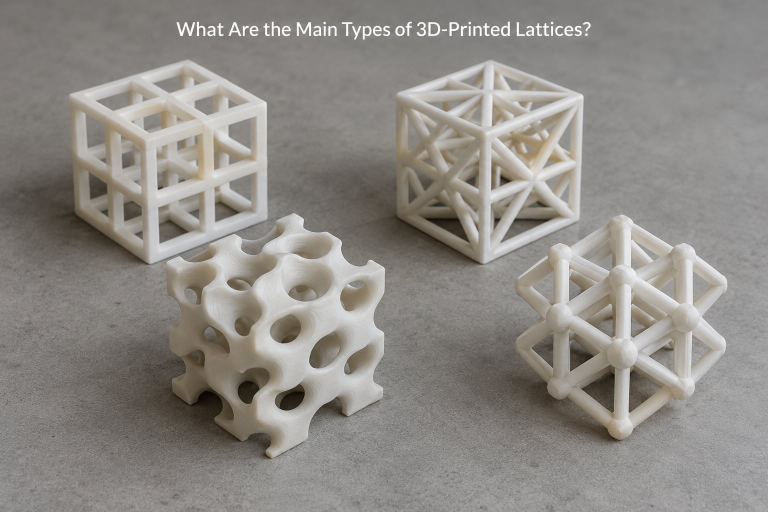
Most printed lattices fall into four families. The differences are geometric, but they show up at the print bed as different failure modes.
- Strut-based lattices. The classic. Straight or curved beams connect at nodes, in configurations such as cubic, octet, Kelvin or diamond. They are predictable, easy to analyse, and the usual first choice for load-bearing parts because struts can be aligned with the load.
- Planar (2D) lattices. Honeycombs and similar patterns extruded through a thickness. Very efficient in one plane, stiff in that plane, and weak out of plane. Common in panels, sandwich cores and protective inserts.
- Triply periodic minimal surfaces (TPMS). Gyroid, Schwarz P, Schwarz Primitive and relatives. A mathematically smooth surface that divides space into two interpenetrating networks, with no sharp corners for a nozzle to worry about. They divide the interior into open channels, which is what makes them useful for filters and heat exchangers.
- Surface-based and shell lattices. A skin wrapped around a hollow interior, sometimes with an internal core added. These save the most material for non-structural parts and for cosmetic shells.
Hybrid designs mix them, often by adding solid material where load concentrates. Variable-density lattices push that further: thick cells in one region, thin cells in another, graded along the part so the density follows the stress field.
| Lattice type | Behaviour | Hardest thing to print | Typical use |
|---|---|---|---|
| Strut (cubic, octet, diamond) | Stiff, predictable, can be anisotropic | Nodes and strut-to-wall junctions | Brackets, arms, structural frames |
| Planar (honeycomb) | Very stiff in-plane, weak out of plane | Keeping flat top and bottom skins bonded | Panels, sandwich cores, guards |
| TPMS (gyroid, Schwarz P) | Isotropic, smooth deformation | Surface finish; requires fine resolution | Filters, heat exchangers, bone-like scaffolds |
| Surface or shell | Light, mostly cosmetic strength | Denting and layer adhesion on thin skins | Enclosures, housings, display parts |
| Variable-density hybrid | Stiffness follows the stress field | Machine time and material use | Performance parts, implants, weight-critical parts |
How lattice structures differ from ordinary infill
Infill and lattice fill the same space but answer different questions. Infill asks “how do I make this shell strong without wasting filament and print time?” A lattice asks “where does this part need material, and how little of it can I get away with?”
The technical difference is in what you control. Infill density is set as a percentage inside a slicer, and you have little say over cell geometry beyond picking a pattern. In a lattice, the unit cell, strut diameter, cell size, orientation and density are design parameters that you choose deliberately, usually informed by simulation.
Practically, infill parts are easy to print because the slicer handles overhangs and keeps the pattern attached to the walls. A designed lattice can contain features the slicer cannot rescue. If the lattice does not need to carry load, infill is usually the right answer. If it does, a lattice lets you place the material deliberately.
Where Are Lattice Structures Used?
Different sectors latch onto different lattice properties, and that is why the same geometry turns up in very different parts.
- Aerospace and drones. Brackets, hinge arms, seat frames and heat-exchanger cores. Here the driver is mass, because every gram removed on a flying vehicle is fuel or range saved.
- Automotive. Brake callipers, engine covers and crash absorbers. Racing teams use lattices to shed mass in rotating parts; production cars use them for impact energy management.
- Medical implants and prosthetics. Trabecular, bone-mimicking lattices. Bone grows into open, porous structures, so a printed implant with a controlled porosity supports osseointegration in a way a dense polished surface does not. Research on lattice bioinks has found them more porous with better flow behaviour than rectangular printed sheets, which matters for cell and nutrient delivery in tissue engineering.
- Tissue engineering scaffolds. The same porosity logic, at a smaller scale, to give cells something to attach to and grow through.
- Heat exchangers, filters and catalytic supports. This is where TPMS wins outright. The smooth, continuous channels have no corners to trap debris or block flow, and the enormous internal surface area does the work of heat transfer.
- Footwear and consumer electronics. Lattice midsoles spread impact while staying light; lattice speaker grilles and drone frames cut weight without looking like engineering samples.
How Do You Design a Lattice for 3D Printing?
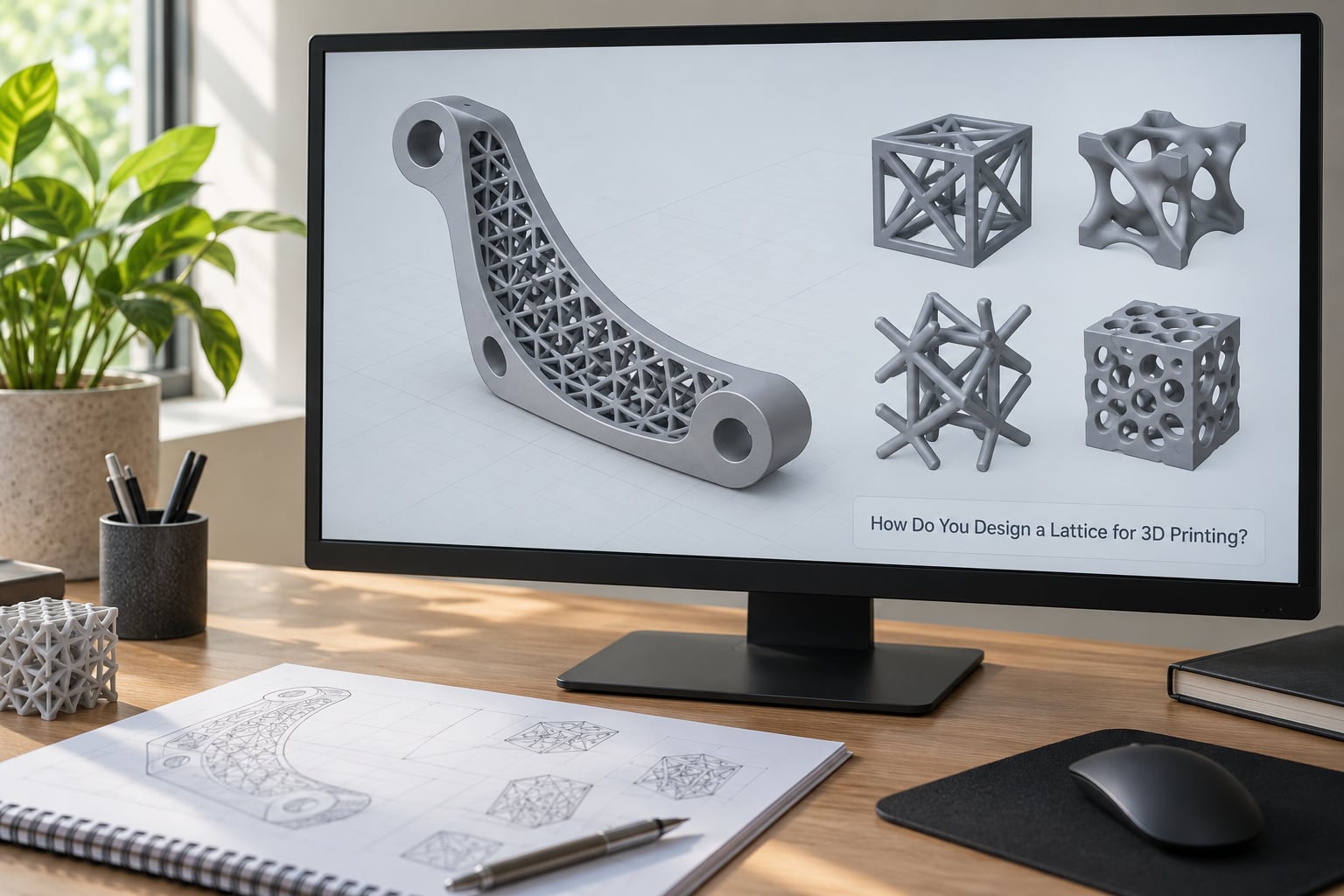
Good lattice design starts with the load, not the pattern. Work through this sequence and you avoid most of the disappointments.
- Define the load and the target property. Write down what the part does: carries a static load, absorbs a crash, dissipates heat, or simply needs to hold shape. Also state the property you care about. Stiffness, strength and energy absorption pull in different directions.
- Keep solid material where it matters. Leave the load introduction points, mounting faces and bolt holes solid. A lattice that begins exactly at a hole or a bearing face will crack there first.
- Pick a unit cell. Choose a geometry whose struts you can point along the load path. Cubic and octet cells are forgiving; diamond cells are light but softer.
- Set relative density and strut thickness. Start conservatively. Increasing density in small steps and reprinting is cheaper than one print that snaps.
- Set cell size to your machine. The cell should be several times the minimum member thickness your process can produce. Struts thinner than that come out faceted and weak.
- Grade the density to the stress field where it helps. Thin cells in low-stress regions, thicker ones near load paths, and a smooth transition between them.
- Terminate the lattice cleanly. Blend it into the outer skin over a short distance instead of stopping it abruptly. A sudden stop creates a long horizontal bridge and a stress riser in one.
- Check support needs per feature. Assume you need support on any surface that faces downward at less than the self-supporting angle for your process.
- Validate in simulation if the load matters. Finite element analysis on the lattice, not on the solid block it replaced. A solid block will always over-predict the stiffness and under-predict the deflection.
What Unit Cell Should You Choose?
There is no best unit cell, only one that suits the load and the machine. Compare candidates on triaxiality, how evenly the cell resists load in all three directions, along with surface area, anisotropy, print direction and mechanical behaviour.
The cubic cell is the easy start. Struts run along the three axes, self-supporting geometry covers roughly half of it, and its behaviour is well documented. The octet cell is also broadly isotropic and can be stiffer at the same density, at the cost of more trigonometry in the model. The Kelvin cell uses curved struts, which print better than sharp junctions and read as lighter than they measure.
The diamond cell is the lightest and the softest. Its low angle between struts makes it poor at carrying load but excellent at absorbing energy, so it belongs in impact parts rather than brackets. Gyroid and Schwarz P cells divide space into two smooth interpenetrating networks, so behaviour stays even in every direction, the channels stay open for flow, and the surface carries no sharp corners. Schwarz Primitive works the same way with larger, more open channels.
Match that against the job: cubic or octet for a structural frame, diamond or a low-density gyroid for something meant to be crushed once, and a gyroid with well-defined channels when fluid or gas has to move through the part. If the part will be printed rather than machined, favour whichever cell keeps the most struts above your machine’s minimum member thickness.
Which 3D Printing Process Works Best?
No process wins outright; each has a resolution limit that sets the smallest strut you can produce. Those published service figures from Protolabs are a good sanity check for what is possible at industrial scale.
| Process | Min. member thickness | Max. bridge distance | Lattice reality |
|---|---|---|---|
| FDM | Roughly one or two extrusion widths | Short; depends on flow | Cheapest, coarsest struts, supports common |
| SLA (resin) | About 0.76 mm | About 7.62 mm | Fine detail, but resin traps in closed cells |
| DMLS (metal) | About 0.76 mm | About 2.03 mm | Strong, heavy supports, trapped powder risk |
| SLS / MJF (powder) | About 3.16 mm | Support-free | Chunky struts, no supports needed, easy powder removal |
| Metal DED | Typically 1 mm or more | Process and nozzle dependent | Repair, cladding and large structures, not fine detail |
Two numbers from that table matter most to designers: the minimum self-supporting angle of 45 degrees, and the minimum member thickness. Self-supporting geometry covers about half of a cubic lattice, so a cubic cell can often print without support. A planar honeycomb or a diamond cell usually cannot, because it puts flat surfaces in mid-air.
Support-free is a real advantage in powder processes. Powder bed machines need no scaffolding at all, which removes both the support material and the risk of someone breaking a fine feature while removing it. Resin and metal powder bed processes have no such luxury.
What Print Settings and Slicing Parameters Matter?
On a desktop printer, the small number of settings that decide lattice quality are strut thickness, layer height and orientation.
Strut thickness. Make every strut at least two extrusion widths wide. On a 0.4 mm nozzle, that means roughly 0.8 mm; below that, thin struts print as one wobbly line with poor layer bonding. With a 0.6 mm nozzle you can push to about 1.2 mm. Follow your machine’s actual specification rather than a generic number.
Layer height versus strut size. A strut one layer tall bonds poorly. Keeping struts at least two, ideally three, layers tall gives a much stronger part. This is why very fine lattices need low layer heights and long print times.
Orientation. Print struts as close to vertical as possible, since an extrusion is far stronger along its length than across its layers. Turning the part so the main load runs along the extrusion direction usually matters more than any infill percentage. Rotate the part in the slicer and compare the preview before committing.
Supports. Tree supports are gentler on finished surfaces than blocky supports, but they still snag on fine lattice features. Where you do need support, make sure it is reachable from outside and can be removed without flexing the part.
Materials. PLA prints the cleanest fine lattices but is brittle and has poor heat resistance. PETG is tougher and handles bridging better, making it the safer default for a first lattice attempt. ABS and ASA need an enclosure and still struggle with overhangs. Nylon and carbon-filled nylon are stiff and light but demanding. TPU makes a lattice that absorbs impact superbly, though fine struts get difficult fast.
Slicer settings for the skin. Because a lattice is only useful if it is attached to the outer surface, check the slicer’s perimeters and top and bottom layer counts. More perimeters mean a thicker load-transfer region where the lattice meets the wall.
What Are the Advantages and Limitations?
The advantages are real and well documented. You cut mass while keeping stiffness, you use far less material for the same job, and you can tune deformation so the part absorbs energy on purpose. You also gain internal geometry that machining cannot produce: closed channels, graded density, and a large internal surface area in one piece.
The limitations are equally real. Printed lattices are directionally dependent, so a part can be stiff one way and weak ninety degrees off. Surface finish on a lattice is poor by default because it is a forest of thin members. Post-processing is difficult: lattices chip, catch on tooling and are awkward to deburr or machine, which is a real problem when a mating surface has to stay flat.
Inspection is another gap. Internal defects in a metal lattice may not show on the outside, so nondestructive inspection is often needed before a part can be trusted. Cost per part stays high for small volumes in metal, and certification for safety-critical use demands documented process control that most hobby workflows simply do not have.
And the most common disappointment: a lattice designed at a relative density that looked fine on screen but printed undersized, because the strut fell below what the machine can actually produce.
How Do You Test and Validate a Lattice Part?
Validation happens in stages, and the early stages are cheap. Begin with a dimensional check: measure a few struts and node diameters on the printed part against the CAD values, since a thin strut printing undersized is the most common reason a part looks right and behaves badly.
Printability trials come next. Print a small block of the same cell at the intended density before committing to the full part. On a desktop machine this is the cheapest insurance available, and it also tells you how many hours the real part will take.
For anything that carries load, test coupons. Small samples of the same geometry at the same density give you a load-displacement curve you can compare against the solid equivalent. Fatigue matters more than static strength for repeated loading, and a coupon run to failure in a few hundred cycles tells you far more than a part that survived a single drop.
In industry, compression and fatigue testing goes alongside nondestructive inspection, because internal flaws in a dense metal lattice are invisible from the outside. Post-print heat treatment and stress relief often follow on metal parts. Treat the material, the process and the intended use as the deciding factors, not the lattice type alone.
Frequently Asked Questions
Are lattice structures stronger than solid 3D-printed parts?
A lattice is not stronger than solid material of the same weight. What it does is deliver far more stiffness and strength per unit of mass, because material is placed along the load path instead of spread through the middle. A solid part wins on absolute strength in every direction; a lattice wins on performance for a given mass. Compare them at equal weight, not equal volume, or the comparison flatters the solid part unfairly.
Can you 3D print lattice structures without supports?
Sometimes. About 45 degrees is the generally accepted minimum self-supporting angle, and a cubic lattice oriented with struts near vertical can print support-free on many machines. Planar honeycombs and diamond cells put flat surfaces in mid-air and usually need support. Support-free options exist in powder bed processes such as SLS and MJF, which need no scaffolding at all because loose powder supports the part.
Are lattices the same thing as infill patterns?
No. A slicer infill pattern fills the inside of a solid shell, chosen mainly for print speed and surface feel, and it is not designed to carry load in a controlled way. A lattice structure is deliberate internal geometry, generated from parameters such as unit cell, strut thickness, cell size and relative density, with mechanical behaviour that has been analysed. Infill suits a lightweight shell; a lattice suits a part that has to carry or absorb something.
Which 3D printers can manufacture lattice structures?
Any process can print a lattice, but resolution decides how fine it can be. FDM prints coarse lattices with struts of roughly one or two extrusion widths. Resin printers reach about 0.76 mm members and give the best surface detail. Metal powder bed fusion reaches similar detail in titanium or steel, while SLS and MJF need coarser members of about 3.16 mm but print support-free. Metal directed energy deposition suits large structures and repair work rather than fine lattices.
Are lattice structures reliable enough for production use?
Yes, provided the lattice is designed and validated for the specific process and material. Aerospace brackets, brake components and orthopaedic implants with lattice interiors are used in production today. The requirement is documented process control, coupon testing in compression and fatigue, and often nondestructive inspection, because internal flaws in a dense metal lattice are not visible from the outside. A lattice optimised in simulation but never test-printed is a prototype, not a production part.
Conclusion
Lattice structures in 3D printing work because material placed along a load path does more for a part than the same material spread evenly. Get the unit cell, relative density, strut thickness, orientation and printing process chosen together, and you get a part that is lighter without being flimsy.
Your first action is simple: take a small block of your target cell size, set a conservative density, and print it at two or three settings before you model anything else. Twenty minutes and a few grams of filament will tell you more about your machine’s limits than any specification sheet.