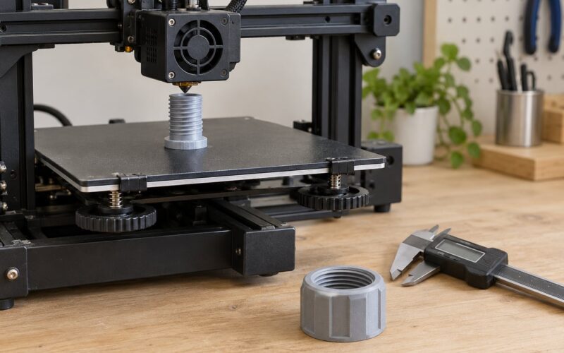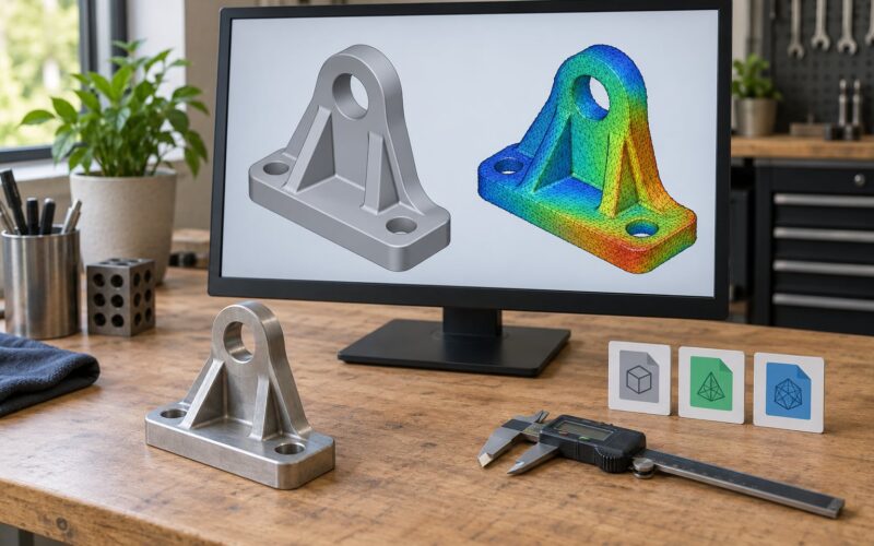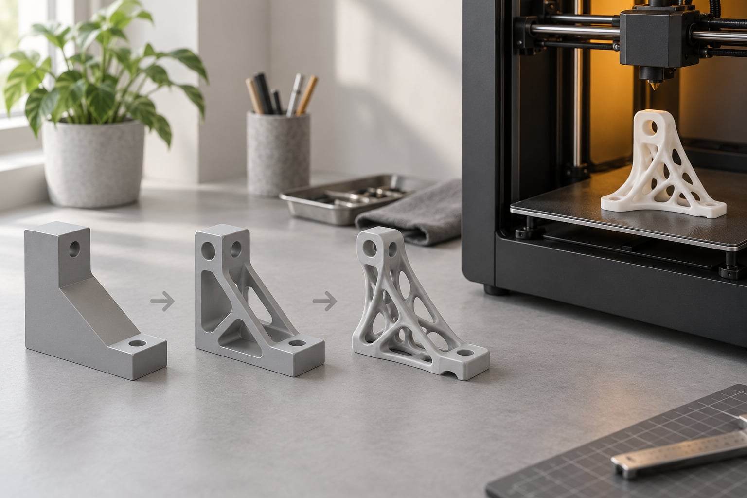
Topology optimization explained for printed parts: it is a simulation-driven way of deciding where material belongs inside a fixed design space, so the part carries its loads with the least possible mass. A solver runs finite element analysis, strips out everything that barely works, and hands back an organic-looking structure. 3D printing is what makes that result real.
Most people meet the idea through a video of a solid block turning into a lattice of ribs. That is the correct mental picture, but it skips the part that decides success or failure: the solver assumes a perfectly uniform, isotropic material, and a printed part is anything but. Get that gap wrong and you end up with a beautiful, optimized, weak part.
Table of Contents
- What Is Topology Optimization and Why Use It for 3D Printing?
- Topology optimization explained for printed parts in one paragraph
- How Does Topology Optimization Actually Work?
- The six-step optimization loop
- How topology optimization relates to generative design and shape optimization
- Topology Optimization Explained for Printed Parts: Key Inputs
- Glossary: the terms solvers keep using
- What Design Loads and Constraints Should You Use?
- The anisotropy problem: your assumptions are set before you pick a build direction
- A worked example: a lightweight mounting bracket
- How Do You Make a Topology-Optimized Part Printable?
- Topology optimization explained for printed parts: the honest printability check
- Which 3D Printing Method Works Best for Optimized Parts?
- When a tuned infill beats an optimized solid
- What Software Workflow Produces a Manufacturable Result?
- Commercial CAD tools
- The free and open-source route
- How Do You Validate and Test a Topology-Optimized Part?
- Validation checklist
- When to bring in a professional engineer
- Frequently Asked Questions
- Does topology optimization always save material?
- Is a topology-optimized part safe to use without testing it?
- Can you 3D print a topology-optimized model with FDM or resin printing?
- Is topology optimization the same as generative design?
- What material properties should I enter for my filament or resin?
- Conclusion: Start With a Manufacturable Design Brief
What Is Topology Optimization and Why Use It for 3D Printing?

Topology optimization is a computational method that redistributes material inside a design domain to minimise strain energy, or compliance, for a given set of loads. You tell it where forces go and what must stay solid. It returns the lightest shape that still carries them.
It is worth separating two things people blur together. Weight reduction is the by-product: the same stiffness with less material. Performance-driven redesign is the real work: the solver is free to invent geometry nobody would sketch, because there is no mould, no fixture and no tool to constrain it.
That freedom only exists because of additive manufacturing. A milling machine needs a rigid billet and a way to reach every feature with a tool. A printer starts with nothing and adds material exactly where it is needed, so curved internal webs and tapering struts cost nothing extra. The organic shapes look odd because they are not designed to be looked at. They are designed to follow load paths.
Topology optimization explained for printed parts in one paragraph
You start from a solid envelope. You mark the zones that must stay solid, such as bolt bosses and bearing seats, and the zones that are forbidden, such as a clearance bore for a cable. You apply the real forces. The solver repeatedly checks the structure, removes the stiffest-to-remove material it can find, and repeats until the target stiffness is met at minimum volume. What comes out has to be recovered into a clean solid model, thickened, support-planned, sliced, printed and tested. The optimisation is the easy part. Most of the work is what you do after it.
How Does Topology Optimization Actually Work?
Under the hood it is finite element analysis on a loop. A denser-based method assigns every element of the mesh a value between void and solid, solves the structure under load, moves material toward high-stress regions, and repeats hundreds of times until the objective stops improving.
The six-step optimization loop
- Define the design space. The solid envelope the solver is allowed to work inside. Start larger than the part you have in mind, because material only moves into space you offered it.
- Lock the non-negotiable regions. Bolt pads, bearing bores, sealing faces and press-fit features. These are excluded from removal entirely.
- Set the load case. Where forces are applied, in what direction, and how much. Keep-out volumes keep the solver out of clearance zones.
- Enter the material. Young’s modulus and density, plus a volume or weight target and a minimum member thickness tied to your printer.
- Set the removal threshold. The fraction of stiffness each region may contribute before the solver is allowed to cut it. Raise it and the result gets lighter and sparser; lower it and the result stays conservative.
- Run, inspect and iterate. Look at where the material ended up. A result with material pooling in a spot that carries nothing is a sign your load case or keep-out zones are wrong.
Solve time depends heavily on mesh density and element order. Practitioners on the Altair community threads cut run times sharply by switching to first-order elements, accepting slightly more approximation in exchange for a result you can iterate on in minutes rather than hours.
How topology optimization relates to generative design and shape optimization
These three get mixed up constantly, and one of them is mislabelled in Fusion 360 itself, where the tool appears as shape optimization in places and topology optimization in others. They are the same solver in different clothing, which is why users assume they are different things.
| Method | What it does | Typical output | Best fit |
|---|---|---|---|
| Topology optimization | Redistributes material through the whole design space to meet an objective | One organic structure | Lightweighting with fixed interfaces |
| Generative design | Runs topology optimization across many variations, materials and manufacturing processes | A ranked set of candidates | Comparing load cases and materials at once |
| Shape optimization (misnamed topology optimization) | Same underlying solver, often applied to surfaces and cosmetic features | One modified shape | Styling, draft and fillet control |
| Slicer infill | Fills a fixed outline with a chosen pattern at the print stage | Shell plus pattern | Simple parts with a known load direction |
The relationship is one-way: generative design uses topology optimization, but topology optimization does not have to be generative. One person’s summary of that on r/GenerativeDesign puts it well, the gap between what topology optimization outputs and what prints is where the real work lives.
Topology Optimization Explained for Printed Parts: Key Inputs
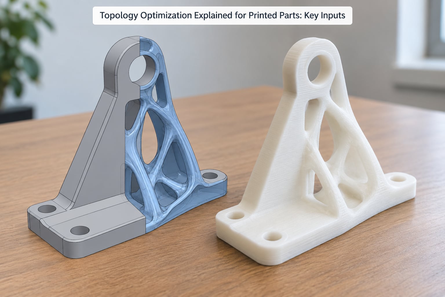
These are the inputs that decide whether a result is useful. The table is split because the difference between a real engineering study and a weekend experiment is mostly about the first three rows.
| Input | What to set | Where the value should come from |
|---|---|---|
| Load case | Force magnitude, direction, and contact area at each interface | Engineering analysis. Guessing here invalidates everything downstream |
| Fixed and preserved regions | Bolted joints, bearing seats, press fits, sealing faces | Geometry, not guesswork. These are the interfaces everything else depends on |
| Material properties | Young’s modulus, density, allowable stress | Datasheets, or tensile coupons you printed yourself for early design work |
| Minimum member thickness | Thinnest feature the printer can actually resolve | Derived from nozzle or laser spot, usually 3 to 4 times extrusion width |
| Manufacturing orientation | Build direction and the overhang angle you can support | Your printer and your support strategy |
| Objective | Minimum volume, minimum compliance, or a frequency target | Choose one. Mixing objectives gives a result that is good at nothing |
Glossary: the terms solvers keep using
Design space (design domain): the envelope the solver may put material in. Load case: one specific combination of forces the part must survive, not a vague expectation. Hardpoint (preserved region): an area the solver is not allowed to modify. Objective function: the number the solver tries to minimise. Minimum member thickness: the floor on how thin any structural member may become, and the single most important input for printability.
What Design Loads and Constraints Should You Use?
Model the forces the part actually carries, including the ones that are annoying, such as vibration, off-axis bolting and handling loads. A bracket that only survives a perfect centred load is a demonstration, not a part.
Constraints matter as much as loads. Keep-out volumes protect clearances. Symmetry constraints simplify a part that is loaded symmetrically. Forbidding material in a region the optimiser keeps using is a signal that your design space is too generous there.
The anisotropy problem: your assumptions are set before you pick a build direction
Finite element analysis assumes an isotropic material: the same stiffness in every direction. A printed part is not. Layer adhesion alone means the strength of an FDM part across the layers can be a fraction of its strength in-plane, and the failure mode is a clean split rather than a gradual yield. On r/3Dprinting, the advice that comes back repeatedly is that topology optimization assumes a much more isotropic material than actual 3D printing is, so use engineering judgement and apply a safety factor.
Here is the part people miss. The solver decides the structure before you ever commit to a build direction, so the print orientation constraint is not a manufacturing detail you add later. It is an input. A useful habit is to run the study twice, once with the part built flat and once standing, and see whether the two results point the same way. If they do not, the load path is sensitive to something you have not modelled.
On the safety factor: for a non-safety-critical jig, a factor of 2 on the printed part’s strength is a common starting point and is roughly what experienced makers settle on. For anything carrying a person, a pressure vessel or a road load, do not pick a number at all, get it reviewed.
A worked example: a lightweight mounting bracket
Start with a solid block 60 mm square, two bolt holes, and a load of roughly 200 N hanging from one edge. Mark the bolt pads as fixed, forbid a 12 mm cable channel in the middle, and set a minimum member thickness your nozzle can actually hold. Run it.
The result is usually a set of ribs sweeping from the loaded edge back to the bolt pads, with the middle hollowed out. That is correct behaviour. Now the part fails for a different reason: two of those ribs are near-horizontal spans that will need support, and the third ends in a 1.5 mm tip the printer will produce as a blob. The optimisation was fine. The recovery step is where this part gets made real.
How Do You Make a Topology-Optimized Part Printable?
The raw output is a rough, triangulated mesh with features thinner than your nozzle and edges pointed at angles no support strategy can rescue. Do not slice it as-is.
Topology optimization explained for printed parts: the honest printability check
- Set minimum thickness from the machine, not from habit. A 0.4 mm nozzle reliably resolves about 1.2 to 1.6 mm walls. A 0.2 mm nozzle still struggles below 1 mm. Enter that as your minimum member thickness so the solver never proposes what you cannot print.
- Check overhangs against your support angle. A 45 degree self-supporting limit is a good target for FDM. Below that, decide per span whether a support is cheaper than removing the feature.
- Watch for trapped material. SLS traps powder in closed cavities, and SLA traps uncured resin. Any pocket the optimiser creates with no drain path is a part you will clean by drilling.
- Rebuild the interfaces. Holes, inserts, threads and split lines do not survive the solver. Re-cut them afterwards on solid geometry, ideally with a fastener that can be replaced rather than a thread cut into plastic.
- Recover smooth surfaces. Most CAD packages have a surface reconstruction or smoothing step. It changes the shape, so re-run a static check afterwards to confirm you did not shave a load path.
Which 3D Printing Method Works Best for Optimized Parts?
Optimized geometry is thin, curved and internal, which suits some processes far better than others.
| Process | Geometry it handles well | Material use | Supports | Main risk |
|---|---|---|---|---|
| FDM / FFF | Thick ribs and beams | Low | Often needed for overhangs | Layer anisotropy and thin-feature loss |
| SLA / resin | Fine internal detail and smooth webs | Low | Many, and tedious to remove | Brittle behaviour and trapped resin |
| SLS | Complex lattices and overhangs | Low | None | Trapped powder, rough surface, weaker in Z |
| SLM / metal | Consolidation-critical parts | High | None | Cost, distortion, post-processing |
FDM is the pragmatic default for most desktop work. SLS wins when the geometry is genuinely overhang-heavy and you want the supports not to exist at all. Metal processes are for parts where the load case justifies them.
When a tuned infill beats an optimized solid
Topology optimization will always use less material than an unoptimized part printed at 100% infill. That is the easy comparison, and it is the one usually quoted. Against a deliberately chosen infill it gets much closer, and the advantage can disappear entirely.
Gyroid and cubic infills are already space frames, and a well-tuned one can be stronger per gram than a topology-optimized solid of the same mass. If your load case is simple and you can orient the part so the load runs along the print direction, print a solid-shell part with a tuned infill and skip the solver. Reserve topology optimization for interfaces, packaging constraints and genuinely multi-directional loads.
What Software Workflow Produces a Manufacturable Result?
Every commercial tool follows the same eight steps, whatever the menu names are: build or import the base geometry, define the design space, mark fixed and forbidden regions, apply loads, enter material and thickness limits, run the solve, recover manufacturable features, then export and slice.
Commercial CAD tools
| Tool | Where topology optimization lives | Worth knowing |
|---|---|---|
| Fusion 360 | Simulation workspace, generate extension | Labelled shape optimization in some menus; the label confuses people more than the tool |
| SolidWorks Simulation | Study, insert, topology optimization | Standard parametric workflow, presets rather than full scripting access |
| Onshape | Simulation, generative design study | Browser-based, so the solve runs on their servers |
| Creo | Live Optimizer and Creo Simulate | Common in regulated engineering teams, with the audit trail to match |
| Altair | SimSolid / OptiStruct | Scriptable automation, first-order element options for fast iteration |
| nTopology | Dedicated computational design | Strong on lattices and multi-material; the raw result needs more recovery work |
The free and open-source route
Three of the eight related searches for this topic ask for a free toolchain, and the honest answer is that it exists but is assembled rather than packaged. CalculiX is a finite element solver that accepts topology optimization jobs and is the engine underneath much of this route. FreeCAD hosts CalculiX, so you can model, mesh, solve and inspect in one open-source package. OpenSnaps handles mesh smoothing and thickness recovery, which is the step that otherwise eats an evening.
If you are comfortable scripting, a Python pipeline with a finite element library gives you more control than any GUI. Users looking for a single end-to-end open-source path generally do not find one, and that is worth saying plainly before you spend a weekend on it.
One practical warning from r/Fusion360: feeding true anisotropic material data straight into a solver is a common route to an invalid material properties error, because most density-based solvers expect an isotropic scalar. The usual workaround is to run the study with a conservative isotropic modulus and handle the direction penalty yourself with a safety factor and a chosen print orientation.
How Do You Validate and Test a Topology-Optimized Part?
A result that looks plausible is not evidence. The solver told you where material was efficient under the model you gave it, and the model is where the errors live.
Start with the cheapest checks. Re-run a static analysis on the recovered, cleaned geometry at the actual print orientation, with the material’s measured properties rather than the datasheet ones. Then print a coupon of the thinnest member and load it, because that is where failure starts. After that, print the part and test it at a load above what it will ever see in service, and watch for layer splitting rather than a clean break.
Validation checklist
- Re-analysis run on the recovered geometry, not the raw mesh
- Print orientation fixed and the load path checked against layer direction
- Material properties from your own coupons, not the nominal datasheet value
- Thinnest member coupon tested and the result compared to the target safety factor
- Interfaces checked by hand: bolt holes, threads and sealing faces
- First article sectioned or load tested before you trust the second one
When to bring in a professional engineer
Simulation is a prediction, and the accuracy is entirely the accuracy of the material model, the boundary conditions and the mesh. Once a failure would hurt someone, the gap between a good guess and a defensible one is a licence, a standard and a signature. Personal organisers, drone frames, tooling and consumer products are fine to iterate on yourself. Anything structural, anything medical, and anything that carries a person needs a qualified engineer and real test data.
Frequently Asked Questions
Does topology optimization always save material?
Always compared with printing the same part at 100% infill, yes. Compared against a deliberately tuned infill it is not. A gyroid or cubic pattern is already a space frame, and per gram it can match or beat an optimized solid of the same mass. Use the solver when interfaces, packaging and multi-directional loads drive the design, not for a simple part with one clear load path.
Is a topology-optimized part safe to use without testing it?
No. The solver reports how material arranges under the model you supplied, so every error in the loads, restraints or material properties carries straight through. The larger gap is anisotropy: the analysis assumes an isotropic material, and a printed part is much weaker between layers. Print a coupon of the thinnest member, load it past your working load, and apply a safety factor on top.
Can you 3D print a topology-optimized model with FDM or resin printing?
Yes, but not straight from the solver. The raw output is a rough triangulated mesh with members thinner than your nozzle. Set your minimum member thickness in the software to roughly three to four times your extrusion width, recover smooth solid geometry, re-cut holes and threads, then plan supports. FDM suits thick ribs; resin gives finer webs but leaves many supports and can trap uncured resin.
Is topology optimization the same as generative design?
Not the same, and one contains the other. Topology optimization is the solver: given a design space and loads, it arranges material to meet an objective, and it returns a single result. Generative design is the wider workflow that runs that solver across many variations, materials and manufacturing processes, then ranks the candidates. A Fusion 360 user asking whether they are different is usually looking at one tool with two names on it.
What material properties should I enter for my filament or resin?
Young’s modulus and density, and for printed parts a safety factor on top, because datasheet values describe injection moulded coupons rather than your layer lines. Most desktop solvers expect a single isotropic value, so run with a conservative modulus and handle direction separately. For real numbers, print a small tensile coupon in your chosen orientation and measure it. That dataset beats any generic table for predicting how your actual part will behave.
Conclusion: Start With a Manufacturable Design Brief
Start with the load case, not the software. Write down the forces, the surfaces that must stay flat and threaded, the clearances that must stay open, and the thinnest wall your printer can hold. Feed those into the solver and the result has a fighting chance of being a part rather than a render.
Then do the unglamorous half properly: recover clean geometry, re-cut the interfaces, fix the print orientation, and test something before you rely on it. Topology optimization explained for printed parts comes down to that sequence every time. The solver places material for the model you gave it. Whether the part survives contact with a printer and a load is still your job.