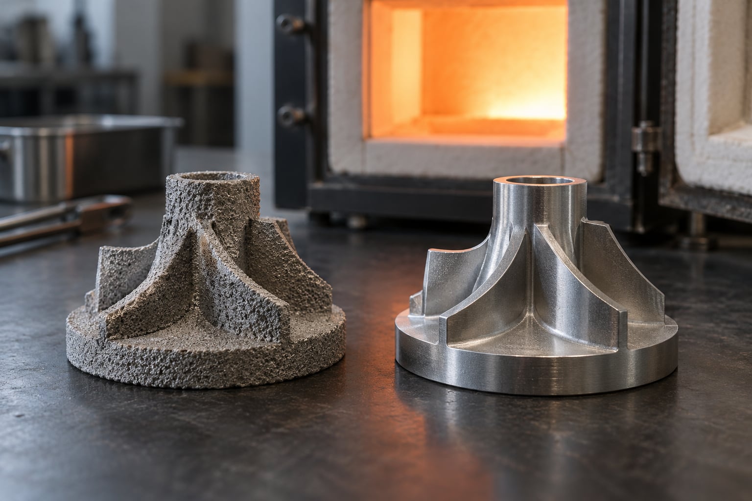
Sintering is the heat treatment that turns a loosely bonded pile of metal powder into a solid part. Heated to roughly 60-80% of its melting point, the powder never fully melts; atoms migrate across the contact points between particles, the part densifies, and it gains real strength.
It is also the step everyone gets wrong the first time. Printers that melt metal layer by layer and furnaces that cook printed or bound powder parts both get called sintering, and they behave nothing alike. This guide separates them, then walks through the process, the numbers, and the failure modes.
Table of Contents
- Sintering Explained in Metal 3D Printing
- Two processes people mix up
- Why Metal Powder Is Sintered After Printing
- How the Sintering Process Works Step by Step
- Sintering Explained in Metal 3D Printing vs. Melting
- Sintering Temperatures, Atmospheres, and Shrinkage
- How Sintering Changes Metal Part Properties
- How Different Metal Printing Technologies Use Sintering
- Benefits, Limitations, and Suitable Applications
- How to Prevent Sintering Defects and Failed Parts
- Frequently Asked Questions
- What temperature is used to sinter metal in 3D printing?
- Does metal sintering cause noticeable shrinkage?
- Why does a sintered 3D printed metal part become brittle?
- Is an inert gas atmosphere required for metal sintering?
- Can the same sintering temperature be used for every metal?
- Conclusion
Sintering Explained in Metal 3D Printing
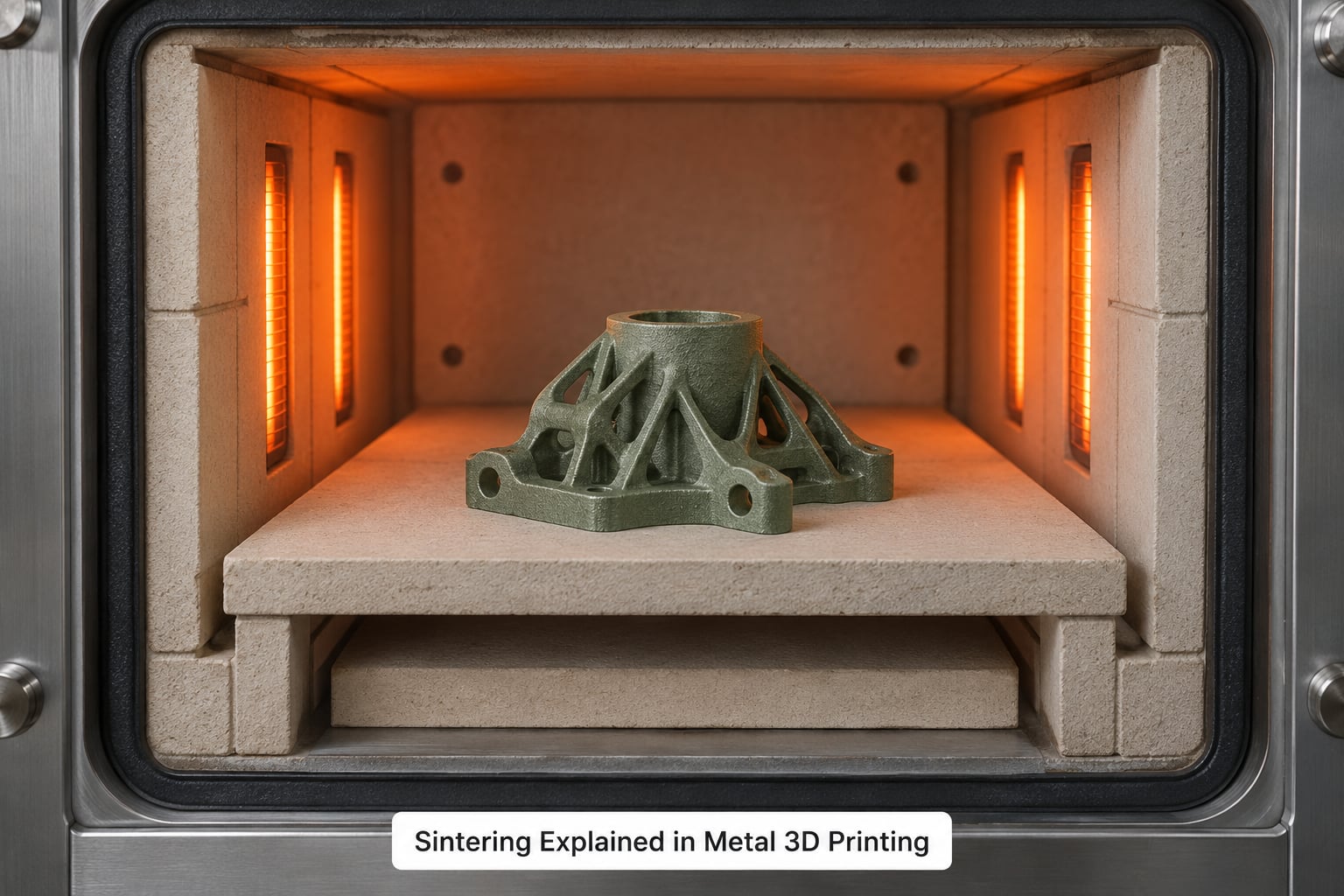
In metal 3D printing, sintering is the controlled heating of a printed metal part below its melting point so that atoms diffuse between powder particles and bond them into one solid piece. The metal never becomes fully liquid, so the part densifies, gains strength and shrinks instead of melting and re-solidifying.
That single distinction separates sintering from melting, and it matters more than it sounds. A part that melts fully tends to come out of a machine dense and dimensionally close to the model. A part that only sinters comes out needing shrinkage compensation, and usually a machining pass.
Two processes people mix up
Sintering explained in metal 3D printing means two different things depending on who is talking. In direct metal laser sintering (DMLS), also called laser powder bed fusion (LPBF) or selective laser melting (SLM), the word describes the laser melting individual powder grains in the build chamber, layer by layer. Despite the name, most metal powder beds are fully melted by the laser.
The second meaning is furnace sintering: a separate, whole-part heat treatment applied after printing, used by binder jetting, metal binder extrusion and metal-filled filament workflows. That is what this guide mostly covers, because that is where the interesting physics and the failure modes live.
Why Metal Powder Is Sintered After Printing
An as-printed metal part is not a metal part. In a powder bed it has been melted, so it is solid metal. In a binder or filament route it is a powder compact held together by a polymer binder, closer to a fragile ceramic than to a billet.
Heat changes that. As the compact rises through the sintering range, atoms at particle contact points move from high-energy surface sites into lower-energy neck positions. Those necks grow, neighbouring particles fuse, and the pore network between them shrinks.
A simple way to picture it: a pile of loose spheres has maybe 60% of the material actually touching. After sintering the same material occupies a much smaller volume with metal bridging across nearly every gap, which is why density climbs toward 95-98% of theoretical and strength climbs with it.
How the Sintering Process Works Step by Step
Debinding comes first. The binder burns out slowly, usually on a long ramp, because rushing it traps vapour inside the part and blows it apart. A thermal debinding step can run many hours and leaves behind a porous, binder-free compact called the brown part.
Then the sinter cycle. The furnace heats the brown part through several ramp stages to a peak temperature below the melting point, holds there so necks can grow and pores can close, then cools under protection.
Three variables decide the outcome. The heating rate sets how fast necks form and how much thermal stress the part carries. The hold time (dwell) sets how far densification goes. The atmosphere sets what the surface chemistry is allowed to do while it happens.
Mechanically, densification moves through stages: surface diffusion first smooths particles without shrinking the part, neck formation then creates bonds, pore shrinkage closes the gaps and pulls the dimensions in, and long holds start trading porosity for grain growth. Get the hold too long and the grains grow, the part gets brittle, and you lose the strength you were trying to gain.
Cooling matters too. Parts come out of a sintering furnace soft enough to scratch with a fingernail, so they are usually supported on ceramic fibre or setters during cool-down to stop them deforming under their own weight.
Sintering Explained in Metal 3D Printing vs. Melting
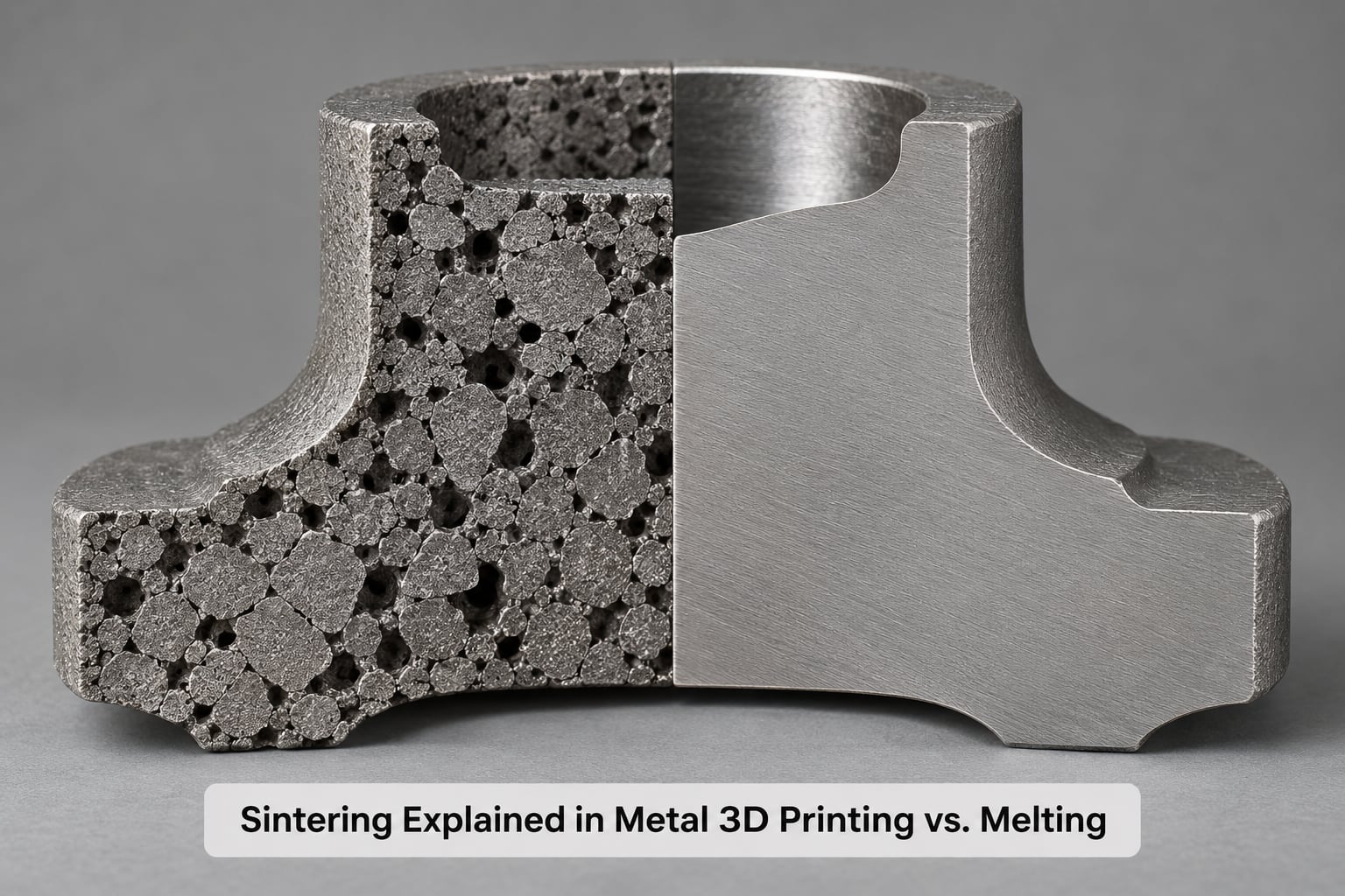
Sintering reaches high density without a melt pool; melting reaches very high density but pays for it with thermal stress, support structures and energy. Choose sintering when geometry is complex, cost matters and a small machining allowance is acceptable. Choose melting when you need the tightest tolerances or a certified fatigue-critical alloy.
| Factor | Sintering | Melting (LPBF/SLM) |
|---|---|---|
| Bonding mechanism | Solid-state diffusion below melting point | Full melting and re-solidification |
| Typical relative density | 95-97% binder jetting, 97-98% metal FFF after sinter | Above 98% as built |
| Linear shrinkage | Often 10-20%, occasionally up to 30% on green metal filament parts | Minimal, roughly 1-3% thermal |
| Surface finish | Rough, porous, generally machined before use | As-built roughness, often bead-blasted or machined |
| Distortion risk | High; thermal gradients on thin features and overhangs | Moderate; residual stress handled by stress relief and supports |
| Energy use | Lower, no melt pool | Higher, laser or electron beam per layer |
| Typical lead time | Print plus a furnace cycle of many hours, batchable | Long build, stress relief, sometimes HIP |
| Best suited to | Prototypes, jigs, jewelry, tooling inserts, lattice and heat sinks | Aerospace brackets, medical implants, load-bearing parts |
Two related routes sit nearby. Liquid-phase sintering uses a small amount of a lower-melting alloy to wet the particles, which speeds densification at lower temperatures. Hot isostatic pressing (HIP) is a pressurised gas cycle that closes internal pores a furnace alone cannot reach, and it is often added after sintering for safety-critical work.
Support-free printing is quietly one of sintering’s best arguments. Binder routes usually print unsupported overhangs and internal channels, which a laser process needs support structures for. On thin, tall or cantileversed features though, unsupported means unsupported during sintering too, and that is where distortion shows up.
Sintering Temperatures, Atmospheres, and Shrinkage
There is no universal sintering temperature. Peak temperature usually lands somewhere between 60% and 80% of the alloy’s melting point, but the exact profile depends on the alloy, the powder particle size, the binder chemistry and the furnace. Always follow the profile published for your specific material and equipment.
| Material family | Representative peak temperature | Typical hold | Atmosphere | Expected linear shrinkage |
|---|---|---|---|---|
| 316L stainless steel | Around 1200-1350 C | 2-4 hours | Vacuum or flowing argon | 15-20% |
| Bronze-filled steel | Around 1050-1150 C | 1-3 hours | Reducing or inert | 15-20%, often anisotropic |
| Copper | Around 900-1000 C | 2-4 hours | Hydrogen or high vacuum | 10-17% |
| Tungsten heavy alloy | Around 1300-1400 C | 1-2 hours | Vacuum | 10-20% |
| Tool steel and carbide blends | Around 1250-1400 C | 2-5 hours | Vacuum or inert | Up to 30% |
Shrinkage compensation is arithmetic once you know your number. If a material shrinks 15% linearly, divide 1 by 0.85 and scale the model by 1.18. Add a machining allowance of 0.2-0.5 mm per surface on features that actually need tolerance, and remember that Z shrinkage is not always the same as X and Y.
That anisotropy is real and it has been measured. Bronze-filled steel parts have been reported shrinking roughly 20% differently in Z than in the print plane, which comes from the layer bonding and how the binder was laid down. Print a small coupon with a hole or a step in it, measure it after sintering, and use your own numbers rather than the datasheet.
How Sintering Changes Metal Part Properties
Sintering raises density, and almost everything mechanical follows density. Tensile strength and yield strength climb steeply as porosity falls, because pores are stress concentrators and a crack finds them first. Hardness rises too, since there is less void space for a load to bite into.
Ductility moves the other way in many sintered materials. Metal powder metallurgy parts are famously less ductile than wrought equivalents, and a part at 95% density behaves very differently from one at 99%, especially in bending rather than tension.
Push the cycle too far and you overshoot: long holds promote grain growth, coarse grains reduce the number of grain boundaries available to stop cracks, and the part turns brittle. Corrosion resistance follows porosity as well, since connected internal pores act as crevices that attack the inside of the part where you cannot see them.
Dimensional accuracy moves in the other direction. Sintering is not a dimensional process. Uniform shrinkage can be designed in, but warping on thin walls, long parts and overhangs means you plan a machining operation rather than trusting the as-sintered geometry.
How Different Metal Printing Technologies Use Sintering
Binder jetting prints a thin layer of powder, sprays liquid binder on the cross-section, spreads the next layer, and repeats. The part leaves the machine as a fragile green body that needs full debinding and sintering in a separate furnace, so this route has the highest shrinkage and the lowest density of the three.
Metal binder extrusion and metal-filled filament print a green part in a familiar FDM or pellet format, again to be debound and sintered off-machine. The filament route is the hobbyist entry point, and it inherits the same furnace cycle as everything else.
Laser powder bed fusion does its bonding inside the build chamber under an argon shield, one layer at a time, with no separate furnace sinter. What is often called a sinter step there is really a stress-relief or HIP cycle afterwards to relieve residual stress and close internal pores.
Cold metal fusion and similar routes use a chemical vapour deposition step to join metal powder particles below their melting point, which removes the separate debinding furnace entirely. That is a genuine workflow difference, not a marketing one.
Benefits, Limitations, and Suitable Applications
The advantages are real. Sintering builds complex internal channels, lattices and unsupported overhangs more cheaply than melting, uses less energy, and lets many parts share one furnace load, which spreads the cost. Copper, bronze and tungsten can be processed at temperatures a consumer furnace can reach.
The limitations are equally real. Linear shrinkage of 10-20% has to be modelled and compensated, residual porosity stays higher than in a melted part, warping and cracking come from thermal gradients, and dimensional accuracy usually means machining afterwards. One r/manufacturing thread summed it up well: sintered metal almost always needs a secondary machining operation, even if the only goal is getting the part off the plate.
Where it makes sense: prototypes and fit checks, production jigs and fixtures, jewelry and decorative work, tooling inserts and wear parts, heat sinks and complex manifolds, and low-volume mass production of simple geometry. Where it does not: anything with a certified fatigue limit, tight fits without post-processing, or a requirement for full density in a safety-critical component.
How to Prevent Sintering Defects and Failed Parts
Most failed sintered parts trace back to one of five things: powder condition, thermal stress, atmosphere, cycle time, or a geometry that cannot survive being unsupported.
| Defect | Likely cause | What to do |
|---|---|---|
| Cracks after sintering | Rapid ramp, thermal gradients, unsupported thin walls | Slow the ramp, add setters and supports, redesign thin sections |
| Warping or curling | Uneven heating, long thin parts, section changes | Lower the part onto a settor, increase hold uniformity, thicken transitions |
| Incomplete bonding, low density | Hold too short or temperature too low | Follow the alloy profile, extend dwell, check furnace calibration |
| Excessive shrinkage | Normal physics pushed past the compensation factor | Scale the model by the calculated factor and verify with coupons |
| Oxidation, blistered or discoloured surface | Air leak or insufficient inert gas | Verify seals, purge properly, check oxygen level with a meter |
| Contamination, dark patches | Residual binder or carbon from oily powder handling | Extend debinding, store powder dry, run a burnout cycle |
| Inconsistent density between parts | Uneven packing or a loose powder bed | Recycle powder properly, keep layer density consistent |
Two habits close most of these gaps. Run a coupon with every material change and measure the actual shrinkage, and add a slow initial ramp below the binder burnout range so thermal expansion does not fight the part’s own structure.
One more safety note, because it gets skipped. Debinding off-gasses, and so does the early part of the sinter cycle. Do this in a kiln with proper venting and capture, wear a respirator when opening a loaded chamber, and never run a furnace cycle unattended in an unventilated space.
Frequently Asked Questions
What temperature is used to sinter metal in 3D printing?
Sintering happens below the melting point, usually at roughly 60-80% of it. Stainless steel powders commonly sinter around 1200-1350 C, copper around 900-1000 C and tungsten blends around 1300-1400 C. These are representative ranges only. The correct peak temperature, ramp rate and hold time come from the profile published for your alloy, particle size and furnace.
Does metal sintering cause noticeable shrinkage?
Yes, and it is the main reason sintered parts need a machining allowance. Linear shrinkage commonly falls between 10% and 20%, and some green metal filament parts shrink by up to 30%. You compensate in CAD by dividing 1 by (1 minus the shrinkage fraction), so 15% shrinkage means scaling the model by about 1.18.
Why does a sintered 3D printed metal part become brittle?
Three things cause it. Leaving residual porosity leaves stress concentrators that cracks find first. Running the hold time too long grows the grains, and coarse grains give cracks fewer boundaries to stop against. A thin or contaminated binder layer from a rushed debind can also embrittle the surface. Match the cycle to the alloy profile and check density before blaming the material.
Is an inert gas atmosphere required for metal sintering?
For most metals, yes. Argon or vacuum prevents oxidation, and copper normally needs hydrogen or a high vacuum to reduce its oxide layer. Stainless steel and tungsten blends work well under vacuum or flowing argon. Aluminium and bronze-filled steels are more forgiving, but atmosphere control still decides how much oxide ends up trapped inside the part.
Can the same sintering temperature be used for every metal?
No. Each alloy has its own melting point, diffusivity and oxide chemistry, so the peak temperature, ramp rate and hold time have to be matched to the material. Steel, copper, tungsten and bronze-filled filaments all sit in different ranges, and using a profile from one on another is a good way to end up with a part that is either barely bonded or badly overcooked.
Conclusion
Sintering explained in metal 3D printing is simpler than the vocabulary suggests: heat a powder part below its melting point, let atoms diffuse between particles, and accept that the part will shrink on the way to becoming metal.
Start by identifying your exact alloy and finding its manufacturer thermal profile, because that determines temperature, atmosphere, hold time and your shrinkage factor. Print a small coupon, measure the real shrinkage in X, Y and Z, then set your scale factors and machining allowances from measured data rather than a datasheet.