3D printing spare parts for aviation means producing replacement aircraft components by additive manufacturing and getting them approved for installation on a specific airframe. The process itself is the easy half. A printed part only becomes legal on an aircraft after it passes through a defined approval route and arrives with full material and inspection records, which is where most home projects quietly stop.
This guide walks through what these parts really are, which components suit the technology, how a design becomes an airworthy spare, what the paperwork costs in time, and where owners and hobbyists hit a legal wall. It is written for maintenance teams, approved-parts specialists, manufacturers, and owners who want a clear answer before printing anything that goes on a real aircraft.
Table of Contents
- What Are 3D Printing Spare Parts for Aviation?
- 3D Printing Spare Parts for Aviation at a Glance
- Which Aviation Parts Are Best Suited to 3D Printing?
- Parts that print well
- Parts to leave alone
- The screening test
- How Does the 3D Printing Process Work for Spare Parts?
- How you get the CAD model when nobody sells it any more
- What Materials Are Used for Aviation Spare Parts?
- What Certification and Quality Controls Are Required?
- How Do You Calculate the Cost and Lead Time?
- What Are the Main Risks and Limitations?
- How Can an Organization Start an Aviation Spare-Parts Program?
- Glossary of terms used above
- Frequently Asked Questions
- Can 3D printed parts be used in commercial aircraft?
- What aviation parts are easiest to manufacture with 3D printing?
- Are 3D printed metal parts as strong as conventionally manufactured parts?
- How are aviation 3D printed spare parts certified?
- Is 3D printing cheaper than buying a traditional spare part?
- Can a 3D printed part replace an approved aircraft component immediately?
- Where to Start With 3D Printed Aviation Parts
What Are 3D Printing Spare Parts for Aviation?
A 3D printed spare part is a component built layer by layer from a digital model, certified for installation on a named aircraft type, and released for sale and installation with traceable documentation. That certification is not optional. A part can be dimensionally perfect and still be unlawful to fit if no approval pathway covers it.
Three things drive aviation toward additive manufacturing for spares. The first is Aircraft on Ground, or AOG, cost: an idle jet burns six figures per hour in lost revenue, lost leases and repositioning costs, so a two-week lead time on a small bracket is expensive in a way that the bracket itself never is. The second is obsolescence. Airframes stay in service for decades, and a duct or a sensor housing can go out of production long before the airframe that uses it does.
The third is consolidation and weight. A single printed bracket can merge eight machined pieces, carry internal channels that would be impossible to mill, and weigh less than the assembly it replaces.
It is worth separating three things people often lump together. A prototype is printed to check a design, and it never flies. A fit-check or pattern print is used in jigs, tooling and measurement, and it stays on the ground. A certified spare part is printed under a quality system, inspected against the applicable specifications, and released with paperwork that lets a maintenance release sign it into service.
3D Printing Spare Parts for Aviation at a Glance
| Part class | Typical material and process | Realistic volumes | Main benefit | Biggest challenge |
|---|---|---|---|---|
| Engine-adjacent brackets and hot-section hardware | Ti-6Al-4V via laser powder bed fusion; Inconel via EBM | Dozens per year | Lead time cut from months to days; part consolidation | Fatigue qualification and full material traceability |
| Ducts, fairings and exterior aerodynamic add-ons | Glass-filled engineering nylon via selective laser sintering | Dozens to a few hundred | Light, complex internal geometry, cheap repeats | Flammability and burn-certification evidence |
| Cabin and interior fittings, latches, vent tubes | Polyamide or flame-retardant polymers via SLS or FDM | Hundreds per year | Weight and cost at low volume | Flame and smoke requirements for cabin locations |
| Structural load-bearing replacement parts | Ti-6Al-4V via laser powder bed fusion | Very low, single digits | Weight reduction and removal of forging tooling | Highest evidence burden; years of substantiation |
| Obsolete and discontinued components | Process matched to the original material | One-off to a handful | Keeps a retired part alive without new tooling | Obtaining a controlled CAD source and drawings |
| Production tooling, jigs and fixtures | High-temperature polymers such as ULTEM and anodized aluminum | Continuous | No fixture shop, no casting patterns | None from an airworthiness standpoint; ground use only |
One row in that table carries most of the commercial weight: tooling. Ground support jigs and fixtures do not need airworthiness approval, which is why many shops adopt additive manufacturing for tooling long before they dare print anything that flies.
Which Aviation Parts Are Best Suited to 3D Printing?
Good candidates share a short list of traits: low or fluctuating demand, complex shape, no need for bulk mechanical properties, an available digital model, and a low consequence if supply stops. The economics fall apart fast when a part is needed in the thousands and a casting would serve.
Parts that print well
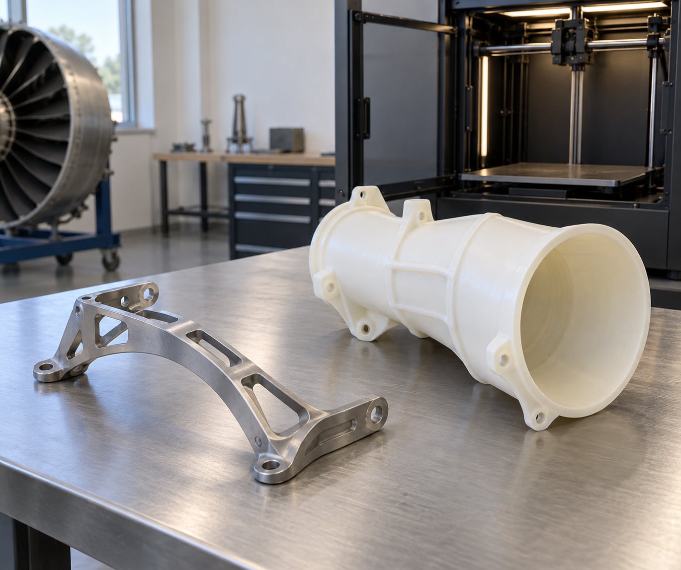
Non-structural housings and covers score well because their job is enclosure, not load. Brackets and clips that consolidate several machined pieces into one piece print well too, especially when a casting would need a core and machining would need a fixture. Ducts, vent tubes and air intake pieces benefit because internal geometry controls airflow in ways a moulded or extruded part cannot match.
Seal supports, spacers and shims are recurring items where the original drawing may be lost. Engine sensor housings, cable and harness brackets, and fairings sit in the middle. Aerodynamic add-ons such as microvanes have their own case: they are non-structural, they sit on the outside where damage is visible, and they can be iterated on flight-test data.
Parts to leave alone
Landing gear, primary structure, and any flight-critical load path stay with conventional processes. The same goes for large castings where material cost dominates, and for anything where fatigue life, not static strength, is the limiting factor and the test evidence does not exist yet.
The screening test
Ask four questions before commissioning a scan. How many are needed in a year? Is a controlled CAD model available? Is the consequence of a porosity defect a cosmetic blemish or a hull breach? And does a qualified supplier already hold the approvals for that process and material? If two of the four answers are uncomfortable, look at the next part on the list instead.
How Does the 3D Printing Process Work for Spare Parts?
The route runs from data to released spare in a fixed order. Each step has an owner and a record, because a gap in the chain is exactly what an auditor finds later.
Step 1, design and data rights. The part exists as a CAD model with a known revision. For current parts this comes from the original manufacturer under licence. For obsolete parts it comes from reverse engineering a physical example, which creates its own problem: the scanned geometry is a copy, and the party commissioning it must own or license the design rights.
Step 2, process selection. The material and machine are chosen against the part’s function, environment and load. This is the table most teams should memorize:
| Process | Feedstock | Suitable part classes | Known limits |
|---|---|---|---|
| Laser powder bed fusion | Metal powder | Titanium and nickel structural or hot-section parts, complex ducts | Layer-direction anisotropy; porosity requires post-processing and inspection |
| Selective laser sintering | Thermoplastic powder | Nylon, glass-filled nylon, flame-retardant polymers for ducts and interior parts | Rough surface needs coating; lower temperature ceiling than metals |
| Electron beam melting | Metal powder in vacuum | Nickel superalloys for engine applications | High residual stress; limited build size and expensive machines |
| Fused deposition modeling | Thermoplastic filament | Tooling, jigs, trim and cabin trim prototypes | Layer adhesion and visible seams limit it for airworthy structures |
| Binder jetting | Metal powder plus binder | Complex metal parts in larger batches | Requires extensive sintering and infiltration steps |
Step 3, printing and monitoring. The build runs under a recorded parameter set. Powder lots are controlled and, for aerospace work, kept under heat and lot traceability so every part can be tied back to a material certificate.
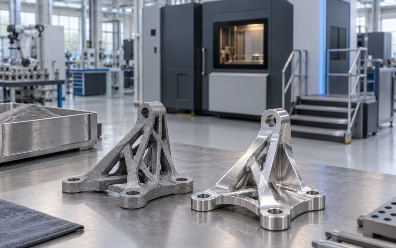
Step 4, post-processing. This is where printed metal becomes usable metal. Stress relief, hot isostatic pressing to close internal porosity, solution heat treatment, ageing, machining of critical surfaces and bores, surface treatments, and non-destructive inspection all happen here. The ordering matters, and so does the record of each operation.
Step 5, inspection and documentation. Dimensional check against the model, coupons for material properties, computed tomography or other non-destructive examination where required, and a First Article Inspection Report that proves the first article met every drawing requirement.
Step 6, approval and release. The part enters one of the approval routes below, and only then does a maintenance organisation buy it, fit it, and sign it into service.
How you get the CAD model when nobody sells it any more
For a supported part the answer is straightforward: buy the data or the spare from the manufacturer and license what you need. For an obsolete part, follow this order.
1. Ask the original manufacturer whether a data package still exists. Some keep archive licences available long after production ends, and that is the cheapest and cleanest source.
2. Check whether an existing Supplemental Type Certificate or Parts Manufacturer Approval already covers the part. A print supplier holding an approval can often supply you the geometry under contract, with the paperwork already in place.
3. Scan a known-good physical example and rebuild the model, then validate the reconstructed geometry against that example by measuring both. Reverse engineering from a degraded part produces a degraded part.
4. Establish ownership before printing anything for sale. The scan belongs to whoever commissioned it, but reproducing a protected design raises separate questions, and copying a file you downloaded from a forum is the clearest way to get this wrong.
5. Generate a full technical data package from the reconstructed model: material, tolerances, surface finish, all drawing notes. An approval submission with a bare mesh file will not pass.
6. Have the model checked against the physical part by someone independent of the reconstruction. Dimension drift in the reconstruction is the most common root cause of a rejected first article.
What Materials Are Used for Aviation Spare Parts?
Material choice is a compromise between weight, strength, temperature, corrosion behaviour, how well the material can be inspected, and how well it has been qualified already. Qualification history often matters more than the numbers on a datasheet.
Glass-filled nylon printed by selective laser sintering is the workhorse for exterior ducts and aerodynamic surfaces. It is light, stiff for a polymer, resists many solvents, and takes complex internal channels. Its weak point is flammability and smoke, which is why parts destined for the cabin need flame-retardant grades and burn-certification evidence.
Unfilled polyamide is easier on the print and inspection side but softer and more moisture-sensitive. High-temperature polyimides such as ULTEM handle tooling and trim applications that exceed the thermal ceiling of nylon.
Ti-6Al-4V is the default for load-bearing and hot-adjacent metal parts. It is light, strong, corrosion resistant, biocompatible, and it has a large body of aerospace qualification behind it. The cost of that pedigree is full lot traceability, post-processing and inspection on every build.
Nickel superalloys such as Inconel cover higher-temperature engine applications where titanium would soften or creep. Aluminium alloys print well for lighter structures and ducting, and stainless steel covers fittings and hardware where strength and wear matter more than weight.
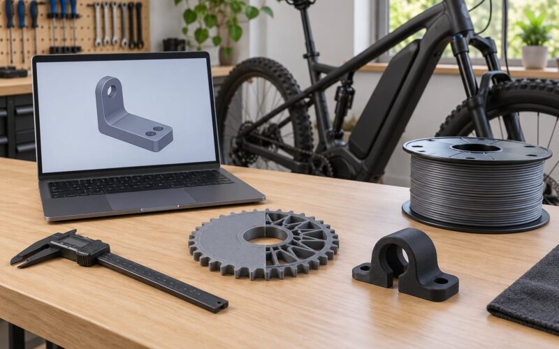
Consumer filaments deserve a straight answer. PLA, PETG and standard ABS have no airworthiness approval for flight-critical use. A desktop printer in a home office is a reasonable tool for patterns, mock-ups, jigs and shed tooling. It is not a reasonable tool for producing a part that goes on an aircraft, whatever the print looks like.
What Certification and Quality Controls Are Required?
Four routes exist for putting an additively manufactured part onto an aircraft, and they differ enormously in who may use them and what evidence is required. Laid them out side by side and the differences are easier to judge.
| Route | Who can use it | What it requires | Typical shape |
|---|---|---|---|
| OEM type-certificate change | The original manufacturer only | Full type-design change, new technical data, authority validation | Installed on new aircraft and on spares sold by the OEM |
| Supplemental Type Certificate | A PMA holder or a modification organisation holding an STC | Approved design, test substantiation, production quality system, installation instructions | Modification to an existing type certificate |
| Parts Manufacturer Approval | A company with a PMA for that part number | Type-design data, own quality control system, part number and markings | A drop-in replacement sold as an alternative to the OEM part |
| Owner-produced part under 14 CFR 21.9 | An owner or an operator producing for their own use | Strict conditions, including not produced for sale and no commercial distribution | One aircraft, owner-made, minimum necessary quantity |
The owner-produced route deserves a warning label. It is limited to the owner’s own aircraft, it cannot be a production run, and the produced part cannot be offered for sale. A part made by an owner and then sold, given away commercially, or produced as a batch is outside the rule, regardless of how good it is. Forum discussions among owners and mechanics keep circling this point, and the honest answer is that it is not a business route under any reading.
Behind the approval sits a quality stack. Aerospace suppliers typically hold AS9100D certification, handle export-controlled work under ITAR registration where applicable, and use NADCAP-accredited special processes for the steps that cannot be verified by inspection alone, such as certain heat treatments, coatings and bond testing. Material arrives with certificates tied to heat and lot numbers, and those numbers follow the part through every operation.
Real examples show what a finished approval looks like. In 2022 EASA certified the first additively manufactured load-bearing spare part, a titanium A-Link anti-icing duct ring produced by Premium AEROTEC for Lufthansa Technik on the IAE-V2500 inlet cowl, where vibration wear on mounting holes drives periodic replacement. Metro Aerospace and RAG hold an FAA Supplemental Type Certificate for laser-sintered microvanes in glass-filled nylon, the first for an additive part on an aircraft exterior, with first article inspection reports and material traceability documented within weeks. Defense Logistics Agency’s Team Travis has produced certified replacement parts on an FAA-certified production printer. Solar Atmospheres has reported heat treating the first FAA-certified Ti-6Al-4V structural components produced through rapid part development.
For context on the earlier wave, GE Aviation’s LEAP fuel nozzle was printed in titanium, consolidated around twenty assembled parts into one, and cut weight by roughly a quarter, going from prototype in 2012 to approval in 2016.
How Do You Calculate the Cost and Lead Time?
The printed part price is rarely the deciding number. The comparison that matters is the printed part against the total cost of getting the part into the aircraft today.
Direct costs to model. Machine time for the build, which for a titanium part can run tens of hours plus a large chamber-prep overhead. Material, which for titanium powder is a rounding error next to machine time but for large polymer prints is not. Post-processing is often the biggest surprise: hot isostatic pressing, heat treatment and machining can exceed print time. Inspection, including computed tomography on critical parts. Certification amortised across the programme. And engineering time for reverse engineering or data licensing.
Ongoing costs to include. Quality system maintenance, calibration, recurring audits, material shelf-life management and staff training. A quality system is a fixed cost you pay whether or not you print anything.
The alternatives you are comparing against. New OEM stock, typically the fastest and the most expensive, with the strongest paperwork behind it. OEM surplus and removed serviceable parts, cheaper with a life history attached. A PMA part, usually cheaper and fully approved for the specific aircraft. Salvage or teardown parts. And a conventional one-off made at a machine shop, which wins for simple metal parts once tooling is ignored.
The avoided cost. AOG downtime is commonly estimated in the six figures per hour, which dominates everything else for a grounded airliner. For a business jet, the equivalent measure is charter cost and lost utilisation. Printing wins decisively when the part is obsolete, low-volume, complex, and needed immediately. It loses when the part is simple, common, and available through a distributor.
Lead time moves in the same direction. An existing drawing plus an approved process can go from release to shipped spare in days to a few weeks. A new part with no certification is months to years, because the evidence, not the print, sets the schedule.
Here is a way to make the comparison concrete. Take one candidate and fill in five cells: annual quantity, price of the current route, current lead time, price of the printed route, printed lead time. Add a sixth cell for the number of aircraft that are grounded per year waiting for that part. Most surprises in these programmes come from cell six, which nobody has ever calculated.
A second trap is amortising certification across the wrong volume. A Parts Manufacturer Approval or Supplemental Type Certificate costs the same whether the part ships five times a year or five hundred. If your demand is tiny, buy from a supplier who already holds the approval and skip the fixed cost entirely.
What Are the Main Risks and Limitations?
Additive manufacturing has real technical limits, and honest programs state them internally rather than discovering them during an investigation.
Anisotropy. Layer bonding direction means a printed metal part rarely matches across and within layers. Z-direction properties are usually the weakest, and a part printed in one orientation cannot simply be rotated later without re-qualification.
Porosity. Unmelted powder and keyhole defects leave internal voids. Hot isostatic pressing and post-processing reduce them, and non-destructive inspection finds them. A process without both is not an aerospace process.
Surface finish and tolerances. As-built surfaces are rough and generally require machining where a seal or a bearing seat is involved. Dimensional accuracy depends on the process, the machine, and the post-processing, which is why a machined critical feature on a printed body is common and sensible.
Fatigue. Static strength data says little about cyclic life. Fatigue testing on printed material is expensive and time-consuming, and the database is far thinner than for wrought or cast stock.
Repeatability. Machine-to-machine and operator-to-operator variation is real. Qualification requires the specific machine, the specific parameter set, and often the specific powder lot range to be controlled.
Data and cybersecurity. A printed part’s design lives as a file, which means version control, access control and supply-chain security apply to the digital model as much as to hardware. That is a new problem for maintenance organisations and a familiar one for anyone who has managed drawing vaults.
Documentation gaps. The most common real-world failure is not a broken part. It is a physically sound printed part with no First Article Inspection Report, no material certificate, and no logbook entry, which the maintenance release cannot accept. A part that fits and works is not the same as a part that is fit for service, and the gap between those two states is where most online confusion lives.
Design data rights. Printing someone else’s design and selling the result raises a separate problem from airworthiness: the CAD file may be copyrighted, and the part may infringe a patent. Contractual rights and product liability travel with the sale, and neither disappears because the part is printed rather than milled.
How Can an Organization Start an Aviation Spare-Parts Program?
Start narrow. Pick a part class that is non-structural, low-volume and currently expensive to source, and prove the pathway end to end before touching anything else.
1. Build a candidate list. Mine the last two years of purchase orders and the spares-discontinued notices. Rank by annual spend, lead time and number of aircraft affected.
2. Screen out the wrong parts. Apply the four questions from earlier: volume, CAD availability, failure consequence, existing supplier approvals. Drop anything load-bearing.
3. Decide make or buy. Buying from an approved additive supplier is faster and cheaper for a first programme. Printing in-house only makes sense once you have the quality system, the machines and the engineers to sustain it.
4. Get the design rights sorted early. License the OEM data if it exists. If it does not, reverse engineer the part and establish who owns the resulting model before you build anything commercial from it.
5. Choose the process from the requirements. Write the requirements first, including environment, loads, temperature and inspection requirements. Then pick the material and machine that meet them.
6. Engage quality and legal before engineering finishes. The approval pathway and the contractual framework cost more calendar time than the design.
7. Prototype and test. Build test articles, run material coupons and mechanical testing, and where required, non-destructive examination and fatigue substantiation.
8. Document everything. First Article Inspection Report, material certificates, process parameters, post-processing records, inspection reports. Assemble them as if an auditor will read them, because one will.
9. Obtain approval and train staff. Certification, production approval, and then training for the technicians and inspectors who will handle it day to day.
10. Measure what happened. Track lead time, cost per part, scrap rate, non-conformance count and aircraft hours saved against the baseline.
One more note on scope. On-aircraft printing for military and emergency use has been demonstrated, including a US Marine Corps effort with portable equipment carried on an aircraft, and airlines have trialed printing at the gate. Treat all of it as a programme to watch rather than a practice to plan around today.
Glossary of terms used above
AOG, Aircraft on Ground. AM, additive manufacturing. AS9100D, the aerospace quality management standard. EBM, electron beam melting. FAIR, First Article Inspection Report. FDM, fused deposition modeling. ITAR, International Traffic in Arms Regulations. LPBF, laser powder bed fusion. NADCAP, the special-process accreditation programme. PMA, Parts Manufacturer Approval. SLS, selective laser sintering. STC, Supplemental Type Certificate. TCDS, Type Certificate Data Sheet.
Frequently Asked Questions
Can 3D printed parts be used in commercial aircraft?
Yes, but only as approved parts. Commercial aircraft carry certified additively manufactured components today, including laser powder bed fusion titanium duct rings and laser-sintered microvanes holding Supplemental Type Certificates. Each part is approved for a specific aircraft type and ships with a part number, material certification and installation instructions. An unapproved printed part installed on a commercial aircraft is not airworthy, regardless of how well it fits.
What aviation parts are easiest to manufacture with 3D printing?
Non-structural, low-volume, complex-shaped parts are the easiest. Ducts, vent tubes, fairings, cable brackets, sensor housings, spacers and cover fittings all print well because they need no bulk mechanical properties and benefit from internal channels and part consolidation. Production tooling and jigs are even easier, since they never leave the ground and need no airworthiness approval at all.
Are 3D printed metal parts as strong as conventionally manufactured parts?
They can reach comparable static strength, but fatigue behaviour is the real story. Printed metal is direction-dependent, with layer interfaces typically weaker, so a part is only valid in the qualified orientation. Hot isostatic pressing and heat treatment improve density, yet the fatigue database for printed material remains far thinner than for wrought or cast stock. Qualification testing decides, not the datasheet.
How are aviation 3D printed spare parts certified?
Through one of four routes: an OEM type-certificate change, a Supplemental Type Certificate, a Parts Manufacturer Approval, or the owner-produced rule in 14 CFR 21.9. Each requires a controlled design, material traceability, inspection records including a First Article Inspection Report, and a production quality system such as AS9100D. The authority validates the evidence before the part can be installed.
Is 3D printing cheaper than buying a traditional spare part?
Sometimes, and the deciding factor is rarely the part price. Direct costs include machine time, material, post-processing, inspection and certification, which can exceed the OEM price for a common simple part. The case is won on avoided cost: six-figure-per-hour AOG losses, months-long lead times, obsolescence and the removal of tooling and jig expense. Low-volume, complex, obsolete parts win; common simple parts do not.
Can a 3D printed part replace an approved aircraft component immediately?
No. A printed part with no approval pathway, no material records and no logbook entry cannot be signed into service by a maintenance release. Under 14 CFR 21.9 an owner may produce a part only for their own aircraft, in minimum quantities, and it can never be sold or distributed. Everything else needs certification first, and the paperwork and testing usually set the schedule, not the print.
Where to Start With 3D Printed Aviation Parts
Start with tooling, not flying parts. A printed jig or fixture teaches your team about powder handling, machine uptime and post-processing without an airworthiness conversation.
Then take one obsolete, non-structural, low-volume component with a known drawing and put it through a full approval cycle. You will learn more about 3D printing spare parts for aviation from that single part than from any amount of reading, because every stage of certification becomes concrete the first time you do it.