The easiest robot part to print first is a flat chassis plate with two motor mount holes, because it needs no supports, prints in one layer on a beginner printer, and gives you a foundation everything else bolts to. Start there, add a wheel module, then a controller board mount. This guide covers which 3D printed robot parts to make first, what each one needs from your slicer, and how to fix the fit problems that end most first builds.
A first robot is mostly structure. Motors, boards, screws and batteries all come off the shelf, and printing handles the part nobody sells you well: the plates, brackets, hubs and covers that hold them at the right angles. The whole thing can be a weekend of printing plus an evening of assembly. Everything below reflects current desktop printing practice in 2026, where a decent PLA spool and a 0.4mm nozzle are enough to build something that moves.
Table of Contents
- What You Need
- Tools
- Filament
- Fasteners and hardware
- Electronics
- Safety equipment
- Step-by-Step
- 1. Plan a Simple Robot Design
- 2. Choose Beginner-Friendly 3D Printed Robot Parts
- 3. Create or Download the Part Model
- 4. Set Up the Print for Accurate Robot Parts
- 5. Print the Parts and Remove Supports
- 6. Assemble the Chassis and Gears
- 7. Add Motors, Wheels, and a Controller
- 8. Test the Robot Safely
- Common Mistakes
- Beginner Tips
- Frequently Asked Questions
- What are the easiest 3D printed robot parts for beginners?
- What material should beginners use for 3D printed robot parts?
- Do I need a 3D printer to make robot parts?
- What are the best free websites for downloadable robot part models?
- How do I make printed robot parts fit together properly?
- Can I build a working 3D printed robot without soldering?
- Conclusion
What You Need
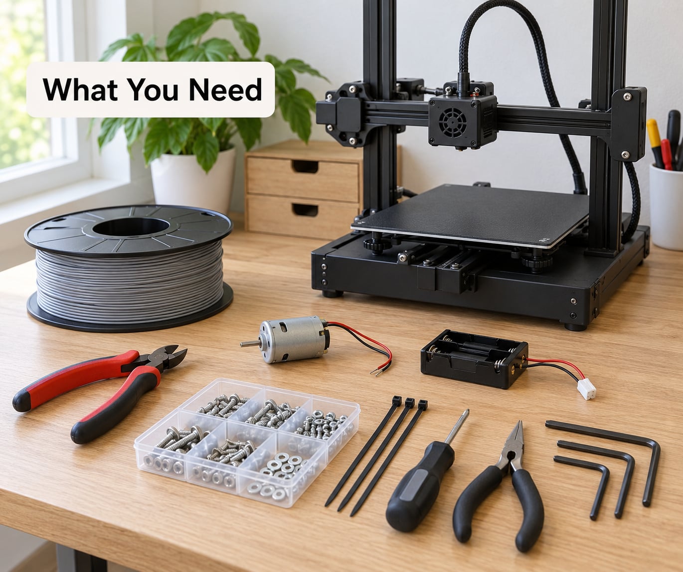
Most of this list you already own or borrow. Buy the electronics and the fasteners, and let the printer make the structure.
Tools
A flush cutter and a small file for cleaning up printed edges. A screwdriver set that includes a 1.5mm and 2.5mm head, because servo horns and motor mounts use tiny screws. Side cutters or scissors for wire, and a multimeter if you have never checked polarity before.
Filament
Start with plain PLA for structural parts, PETG for load-bearing brackets and hubs, and TPU 95A once you want a joint that flexes instead of cracking.
Fasteners and hardware
M2 and M3 machine screws in a few lengths, matching nuts, and a handful of washers. A few zip ties or printed cable clips. Foam tape or double-sided tape for battery and sensor mounting, because glue on a robot is a bad idea.
Electronics
Two DC gear motors with wheels, an Arduino Nano or Uno for a rover or an ESP32 if you want Wi-Fi control, a motor driver such as an L298N or a TB6612FNG, and a matching battery pack. Add MG90S micro servos for arms and grippers, and two or three IR or ultrasonic sensors if you want line following or wall following later.
Safety equipment
Safety glasses if you have ever had a nozzle spit, and a pair of gloves for pulling failed prints off a bed. Keep a pair of needle-nose pliers nearby for hot-end swaps. No soldering iron is strictly required for a first build, and there are ways around that entirely.
Step-by-Step
1. Plan a Simple Robot Design
Choose a two-wheel differential drive robot, sometimes called a rover or line follower. Two motors, one castor, and a flat body is the whole mechanical concept, and it moves under almost any control code you write.
Set the dimensions before you model anything. Measure your motor body length, the bolt spacing on its face, the diameter of the shaft, and the diameter of your wheels. Write those four numbers on paper. Most failed first builds come from designing a chassis, printing it, and only then holding a motor against it to find out it does not fit.
Skip anything with gears, belts, or a differential drive for the first attempt. Every mechanism adds a tolerance problem, and tolerance problems are where first-time builders usually quit.
2. Choose Beginner-Friendly 3D Printed Robot Parts
The parts worth printing on a first build are the ones that take load or need exact alignment. These are also the easiest shapes to print.
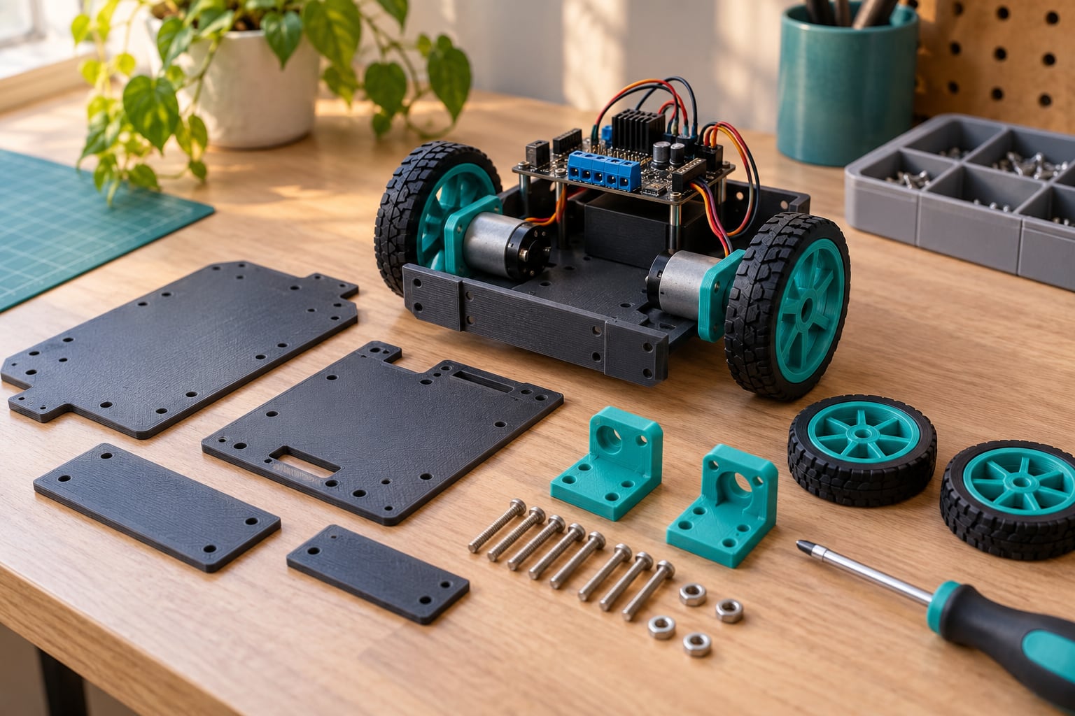
Chassis plate. A flat plate, roughly 120 by 90mm, with holes for the motors, the controller, and the battery. Prints in minutes with no supports.
Motor mounts. Printed brackets that hold a motor square to the chassis. Printed in pairs and matched, they keep the wheels parallel, which is what stops a rover from veering.
Wheel hubs. D-shaped or hexagonal hubs that screw or press onto a motor shaft. Printing these saves you the classic problem of a wheel that is slightly off-axis and wobbles at speed.
Standoffs or spacers. Short cylinders or hex pillars that lift the electronics board off the plate so soldered pins do not scrape.
Cable clips. Tiny channels that route motor wires along the chassis. Two of these stop the wires that snag the wheel and reverse your commands at random.
Sensor mounts. Brackets that hold IR or ultrasonic sensors at a fixed height and angle. Height matters more than position, and a bracket lets you adjust it later.
Battery holder and electronics enclosure. A printed tray or box that keeps a pack from sliding and gives you something to hang standoffs from.
Leave gears, suspension, compliant fingers, and print-in-place linkages for a second robot. Gears need tight tolerances, and print-in-place moving assemblies often fail at exactly the moment you want to show someone.
3. Create or Download the Part Model
Most beginners should download rather than model. Sites like Thingiverse, MakerWorld, Printables and Cults3D host thousands of free robot STLs, and an STL is simply the 3D model file your printer reads.
Before printing anything, check the licence on the model page. Look for a Creative Commons tag, and read it carefully: some models are personal-use only, some allow remixing, and a few forbid redistribution. A model with hundreds of reviews and printed make instructions is a safer bet than a bare upload with no feedback.
If you want to change something, a browser CAD tool like Tinkercad handles holes, boxes and rounded shapes without a learning curve. One rule for modifying a downloaded file: never scale a part without re-checking hole sizes, because uniform scaling moves the screw clearance too.
4. Set Up the Print for Accurate Robot Parts
Fit problems in a robot are almost always slicer settings, not bad luck. These settings cover most printed parts on a rover or arm.
| Part type | Material | Layer height | Perimeters | Infill |
|---|---|---|---|---|
| Chassis plate | PLA | 0.3mm | 3 | 20% |
| Motor mount bracket | PLA or PETG | 0.2mm | 3 | 30% |
| Wheel hub | PLA or PETG | 0.2mm | 4 | 40% |
| Gears | PETG | 0.15mm | 4 | 60% |
| Joint or bumper | TPU 95A | 0.2mm | 3 | 15% |
| Enclosure or cover | PETG | 0.3mm | 3 | 15% |
For a screw hole, print it undersize. A nominal 3mm hole should be modelled at 2.7 to 2.8mm in PLA so the screw self-taps and the plastic does not split. That single habit removes the most frustrating assembly problem beginners hit.
For a press-fit hole, aim for a 0.2mm clearance between the printed part and whatever goes into it, and test-fit before you glue anything. Multi-perimeter walls around holes matter more than infill, so raise perimeters before you raise infill.
5. Print the Parts and Remove Supports
A good print looks flat on the bottom, has visible layer lines with no gaps, and holds a straight edge against a table. If the corners of a plate lift off the bed, that part needs reprinting, not rescuing.
Remove supports while the plastic is still slightly flexible, and break them off along the natural layer direction rather than prying. Push a screwdriver tip into the support socket and rotate it like an Allen key. Then ream every hole with the screwdriver shaft so burrs go away.
Test-fit the whole stack dry before fastening one screw. Chassis, motor mounts, hubs, spacers. If something binds now, more force later will crack it.
6. Assemble the Chassis and Gears
Work from flat plate upward. Insert one motor into each mount, tighten its screws evenly on both sides, and check that the shaft sits parallel to the ground. Repeat on the other side and measure the gap between both wheel mounting faces, because a half millimetre difference is enough to make a rover pull to one side.
If you are adding gears later, press a shaft into the hub first rather than drilling it after mounting, and check that the gear mesh has about one tooth of visual overlap. Back the assembly off slightly by the backlash amount if it binds. Never force a printed gear to mesh; it will strip at the teeth, and PETG holds up better there than PLA.
7. Add Motors, Wheels, and a Controller
Wire each motor to the driver board first with the robot on the bench, not on its wheels. Power the board, run a short test that spins each motor alone, and confirm both spin the same direction. If one runs backwards, swap that motor’s two wires at the driver. Reversed wiring on both motors sends you in a circle, which looks like a bad design rather than a polarity problem.
Mount the controller on printed standoffs so the underside of the board clears the chassis, and fix the battery holder so the pack cannot shift. Route motor cables through the printed clips and leave at least 20mm of slack at the board. That slack is what lets you open the robot up to change a sensor instead of rebuilding it.
Route every wire away from wheel paths and away from the castor. Wire touching the ground at speed is the single most common cause of a robot that resets mid-run.
8. Test the Robot Safely
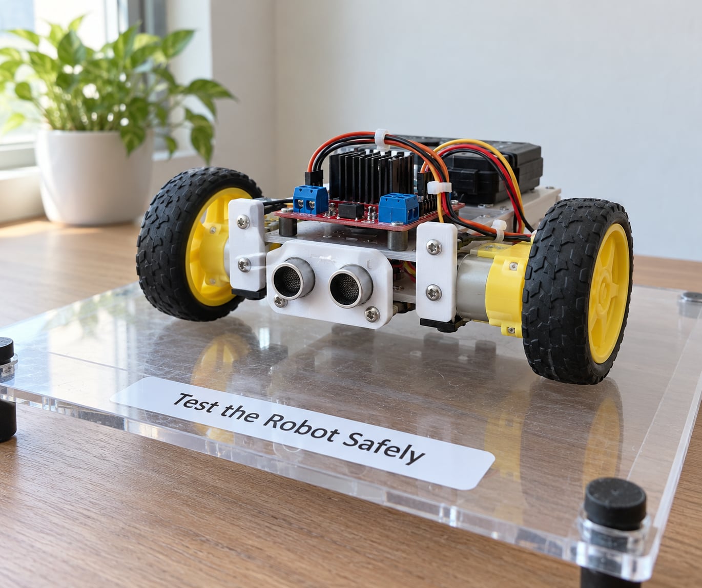
Run the first test with the wheels lifted off the surface. Hold the chassis at wheel height so nothing near your fingers, give a short throttle command, and check the direction again. Do this before you set it down.
Then place it on a large clear floor, not a table. Wheels at speed off a desk edge are how beginner robots end up in pieces. Run for five minutes and touch the motors. Warm is fine, too hot to hold is not; a motor that needs a cooling gap or a lower duty cycle will fail later under load.
Make small changes from there. Add a sensor mount once driving is reliable, then code a mode that uses it. A wander routine is a good first program because it needs no sensor and still proves the drivetrain.
Common Mistakes
Corners lifting off the bed. A warped plate will never bolt flat. Clean the bed, raise the nozzle closer for that first layer, add a brim around the plate, and enclose the printer if you draft. PETG sticks better and warps less than PLA, so switch material if a large flat part refuses to behave.
Holes too tight, or screw heads splitting the plastic. Print holes 0.2 to 0.3mm undersize and add a washer face on the entry side. If you have already printed them, run a drill bit through by hand rather than forcing the screw, and ream the hole with a screwdriver shaft until the bit slides in with no wobble.
Supports breaking through the surface. Support material is rougher and harder to remove than the part. Z-hop a little higher, lower the interface layer count, or redesign so the part self-supports by angling the overhang to about 45 degrees or less.
Gears binding or stripping. Print gears at 0.15mm with 4 perimeters in PETG, check the shaft hole is actually round after printing, and ream it. Any wobble in a gear train shows up as a robot that shakes rather than turns.
Parts that are slightly undersized overall. Scaling a model changes every hole inside it. Scale only decorative pieces, or model at true size from the start and fix tolerances in the CAD file.
Wheel wobble. Either the hub is cracked around the shaft, or the shaft is not perpendicular to the wheel face. Check the hub bore by pressing it onto an axle and spinning it; if it rocks, reprint the hub at 4 perimeters.
Motors running hot. The usual cause is a driver set too high for small motors, or continuous stall. Lower the speed, add a small delay between direction changes, and check nothing is dragging on the drivetrain.
Robot reverses at random. Almost always a loose motor wire touching a wheel or a noisy power rail brownout. Re-seat every connector and add a small capacitor across the motor terminals if it is still intermittent.
Beginner Tips
Print one of everything before the full set. A single wheel hub test tells you in twenty minutes whether your clearance numbers are right, and it saves reprinting twelve of them later.
Be generous with clearance. It feels wasteful for the first few prototypes and it is the difference between a build that goes together and a build that ends in a bag of screws.
Label parts as they come off the bed with a marker while you are still at the printer. Two identical brackets become an afternoon of confusion otherwise.
Build in modules. One chassis module with wheels and motors, one sensor module, one gripper module. Modules let you debug one section at a time instead of rebuilding everything after each fault.
Add electronics in stages. Chassis and drivetrain first, then a controller, then sensors, then servos. Each stage is something you can test on its own.
Write down settings that work. When a mount prints perfectly, save that profile with a name like motor-mount-PETG-0.2. Your own notes will beat any guide six months from now.
Support the designers whose files you print. Leaving a rating or a printed photo on the model page helps the next beginner the same way helpful posts help you.
Frequently Asked Questions
What are the easiest 3D printed robot parts for beginners?
A flat chassis plate with motor holes is the easiest first print: no supports, one layer, and a couple of hours at most. After that, motor mount brackets, wheel hubs, standoffs and cable clips are all simple shapes that print reliably in PLA at 0.2 to 0.3mm layers. Save gears, suspension and print-in-place linkages for a second build, because those are where tolerance problems show up.
What material should beginners use for 3D printed robot parts?
Plain PLA for most structural parts. It prints at a lower temperature, hardly warps, and needs no tuning on a beginner printer. Move to PETG for load-bearing brackets, hubs and gears, since it absorbs impacts and heat better. TPU 95A is worth having for joint bumpers, wheel tires and flexible fingers once you want parts that damp movement.
Do I need a 3D printer to make robot parts?
You need one for the structural parts, because chassis plates, brackets and gear trains are rarely sold off the shelf in the sizes your project needs. Many beginners start with a kit for the motors, driver, controller and wiring, then print the frame and covers themselves. Order kits and printed files online and you can have the hardware in hand on the same day the plates finish printing.
What are the best free websites for downloadable robot part models?
Thingiverse, MakerWorld, Printables and Cults3D all host large free robot model collections. Judge quality by review count, photos of printed results, and whether the designer published a bill of materials. Always read the licence tag before printing: some models are personal use only, some allow remixing, and a few forbid redistribution.
How do I make printed robot parts fit together properly?
Give every screw hole a clearance by printing it 0.2 to 0.3mm undersize for a 3mm screw, and give every press-fit hole about 0.2mm clearance. Keep at least three perimeters around holes, since wall strength matters more than infill there. Dry-fit the whole assembly before tightening anything, and ream holes with a screwdriver shaft to remove burrs.
Can I build a working 3D printed robot without soldering?
Yes. Use screw terminal or JST connectors for the motors and driver board, and use a microcontroller board with headers already fitted rather than a bare chip. Wire the battery holder and driver to screw terminals, and leave the board accessible through an open enclosure. Some builds avoid it entirely by using a pre-soldered battery pack and a driver board that plugs straight in.
Conclusion
Print a chassis plate with two motor mounts and matching wheel hubs first. That is four parts, roughly an hour of printing each, and it gives you a drivetrain you can test immediately. Wire the motors to a driver, confirm both spin the same way with the wheels off the surface, and only then think about anything else.
Sensors, grippers and gear trains all work better as a second and third build, once you already know how your printer handles clearances and holes. Build a rover that drives, then add the interesting mechanisms one at a time, and you will still be making robots when the more complicated designs would have walked away from you.