Metal 3D printing is additive manufacturing with metal: a 3D CAD model is sliced into thin cross-sections, a machine spreads fine alloy powder across a build platform, and a high-energy laser or electron beam melts only the powder matching each layer’s outline, repeating the cycle until the part is solid.
That definition is the whole idea, but the details are where metal separates from plastic printing. The powder has to be spread at 20 to 50 microns, the chamber has to hold oxygen below roughly 25 parts per million, and the finished part is almost never usable straight out of the machine. In 2026, most metal printing runs through some flavour of powder bed fusion, then goes to a furnace and a CNC machine before anyone measures it.
Table of Contents
- How Does Metal 3D Printing Work?
- The Main Metal 3D Printing Methods
- Powder bed fusion: SLM, DMLS and EBM
- Binder jetting
- Bound powder extrusion
- Powder Bed Fusion Step by Step
- 1. CAD model and orientation
- 2. Slicing
- 3. Chamber setup and purge
- 4. Powder spreading
- 5. Selective melting
- 6. Platform step-down
- 7. Cooling and de-powdering
- 8. Support removal and finishing
- What Is Direct Metal Deposition?
- Which Metals Can Be Used in Metal 3D Printing?
- Why Metal 3D Printing Is More Complex Than Plastic Printing
- What Happens After the Part Is Printed?
- How Do Designers Prepare a Part for Metal Printing?
- What Are the Main Advantages and Limitations?
- Frequently Asked Questions
- Is metal 3D printing safe?
- What is the most common metal 3D printing process?
- Can metal 3D printers print at home?
- How accurate is metal 3D printing?
- Does metal 3D printing require support structures?
- How much does a metal 3D printed part cost?
- Where to Start
How Does Metal 3D Printing Work?
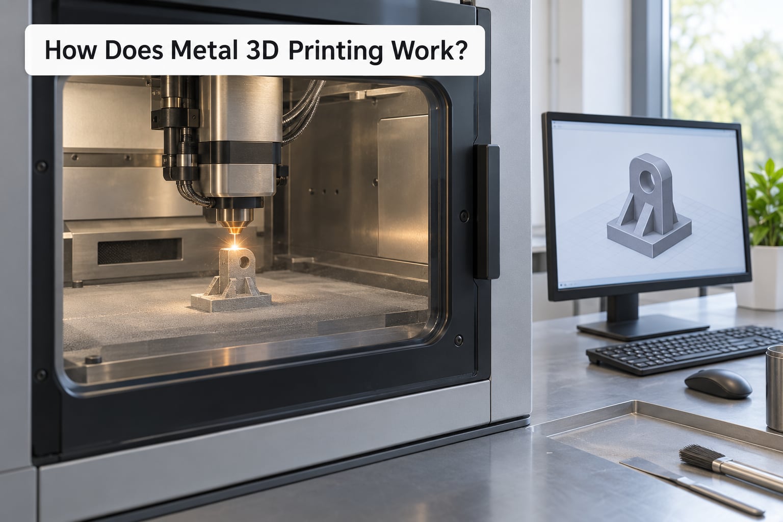
Short version: a digital model becomes slices, the slices become a laser or beam pattern, the pattern melts metal powder one thin layer at a time inside a sealed argon-filled chamber, and the finished part gets support removal, heat treatment and inspection. Every metal printing technology shares that spine, even though the energy source and feedstock change.
The shared pipeline, in the order it happens:
- Model creation — a part is designed in CAD, usually with wall thickness and support geometry in mind from the start.
- Slicing — software cuts the model into 2D cross-sections and writes the toolpaths, scan strategy and support structures into machine instructions.
- Machine setup — powder is loaded and sieved, the build platform is preheated, the chamber is purged with inert argon, and a test coupon is usually run.
- The build cycle — a recoater spreads powder, the beam fuses the layer’s cross-section, the platform steps down one layer, and it repeats for thousands of layers.
- Cooling and de-powdering — the part cools in argon, loose powder is vacuumed or brushed off, and the part is removed from the platform.
- Post-processing and inspection — supports come off, the part is stress relieved or annealed, critical surfaces are machined, and it gets measured and tested.
One thing surprises newcomers: a metal build is slow. A small part on a lab machine can take hours, and a dense industrial part can run for days, because each layer is maybe 30 to 60 microns thick and the recoater only moves once per layer. Layer count drives build time far more than part size does.
The Main Metal 3D Printing Methods
There are four families of metal printing, and they differ mainly in one question: how does the metal become solid? Two melt it, one glues it, one squeezes it out as a filament.
| Method | Energy source | Feedstock | Atmosphere | Layer thickness | Typical use |
|---|---|---|---|---|---|
| Laser powder bed fusion (SLM, DMLS) | Fibre laser, 100 to 1000 W | Loose alloy powder | Argon | 20 to 60 microns | Aerospace, medical, tooling, general parts |
| Electron beam melting (EBM) | Electron beam, high vacuum | Loose alloy powder | Vacuum | 50 to 120 microns | Titanium implants, aerospace |
| Directed energy deposition (DED) | Laser, plasma or arc | Powder or wire | Air, argon or shielding gas | 0.5 to several mm | Repair, cladding, very large parts |
| Binder jetting | Thermal curing, then sintering | Powder plus liquid binder | Air, then furnace | 50 to 120 microns | Patterning, sand cores, low-load parts |
| Bound powder extrusion | Plastic filament extrusion | Metal powder in a polymer binder | Air | 100 to 300 microns | Desktop shops, tooling, small batches |
Powder bed fusion: SLM, DMLS and EBM
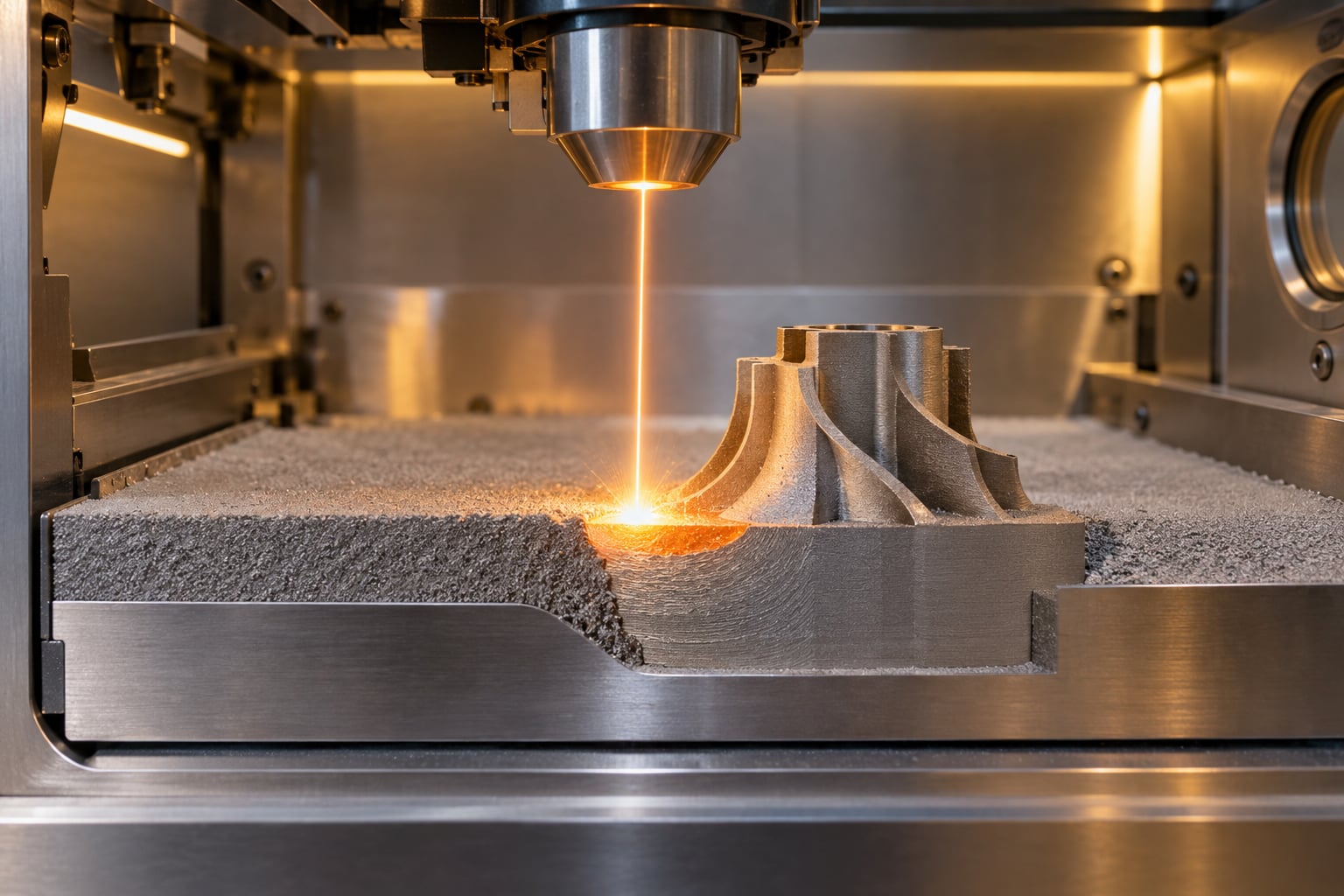
Powder bed fusion, or PBF, is the dominant metal process. A powder bed sits on a movable build platform inside a sealed chamber, and a laser or electron beam selectively melts the layer outline. The powder that the beam does not touch stays loose and gets recycled for the next run.
SLM (selective laser melting) and DMLS (direct metal laser sintering) are two marketing names for the same machine family. The word “sintering” in DMLS is a leftover from the polymer world; the powder in a metal chamber is fully melted, not sintered. In practice, an SLM machine will run DMLS settings and vice versa.
EBM swaps the laser for a focused electron beam and drops the argon chamber for a high vacuum. The build platform itself becomes a copper heat sink, keeping the part at several hundred degrees Celsius. That removes a layer of residual stress and makes titanium nearly stress-free as built, at the cost of a coarser surface and a rough finish on down-facing features.
Binder jetting
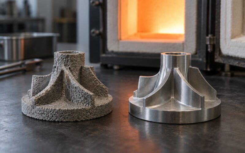
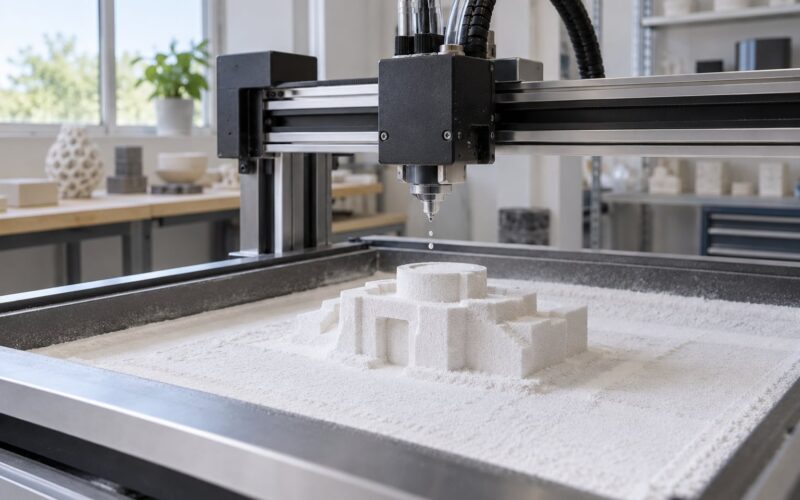
Binder jetting prints a liquid glue onto powder, layer by layer, producing a fragile part called a green part. The green part is then de-bindered and sintered in a furnace, where the powder particles fuse and the part shrinks by roughly 15 to 20 percent. Infiltration with a lower-melting metal is sometimes used to fill the remaining porosity.
The big advantage is speed, since the printer itself behaves much like a paper printer. The big drawback is porosity and its effect on fatigue life, which is why load-bearing and safety-critical parts usually go to a melting process instead.
Bound powder extrusion
Bound powder extrusion is the technology behind the desktop metal printers that showed up in workshops a few years ago. Metal powder is mixed with a waxy or polymer binder and extruded as a plastic-like filament, layer by layer, on a modified FDM machine. The part then goes through catalytic debinding, which pulls the binder out at a controlled rate, followed by sintering.
Support material in these systems is the same metal powder in a different form, so supports wash or brush away instead of being cut off. Desktop machine owners on forums report far better surface finish and much faster cycle times on small parts than industrial powder bed machines deliver, which is exactly where these machines compete.
Powder Bed Fusion Step by Step
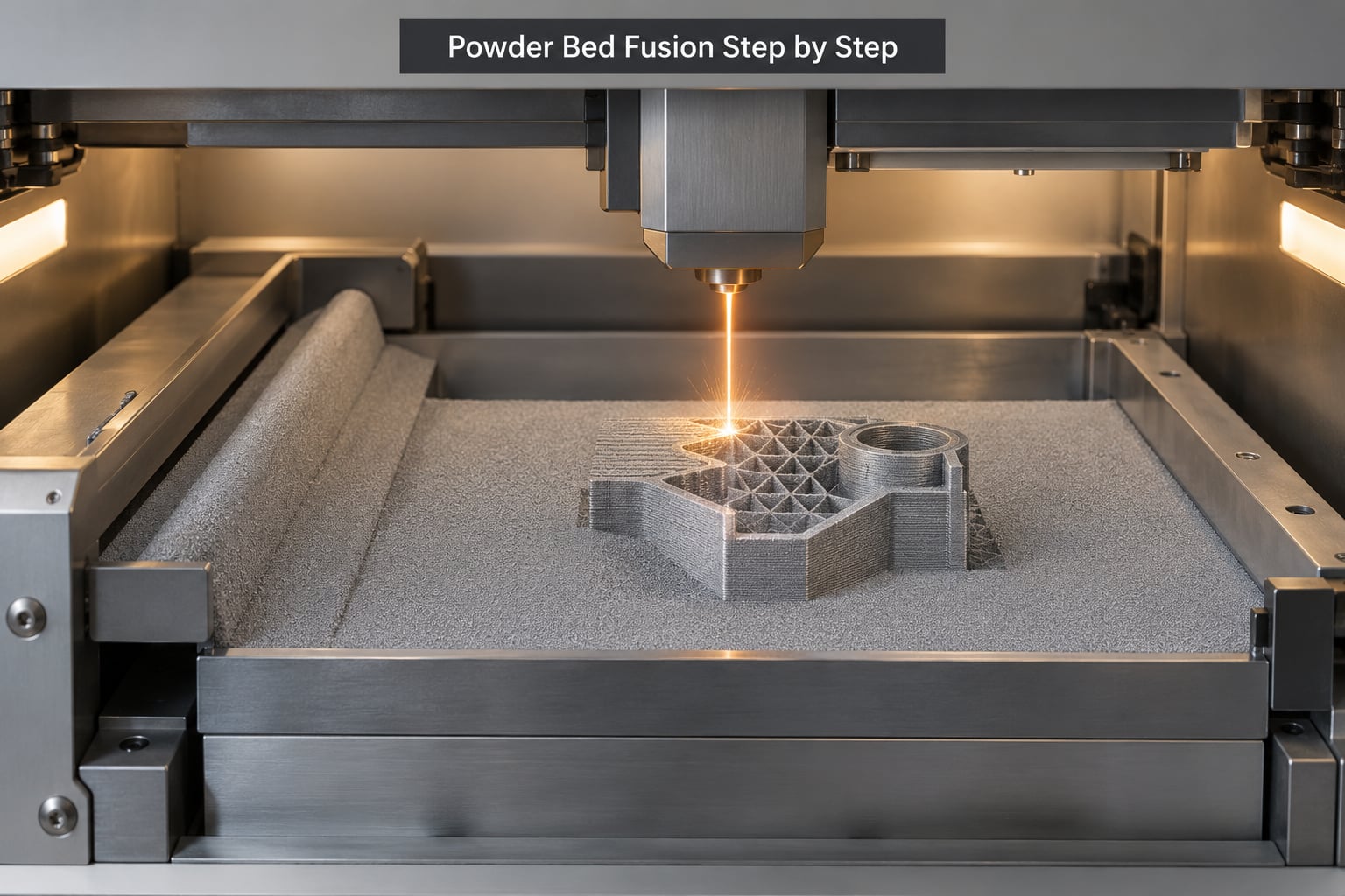
This is the process most people mean when they ask how metal 3D printing works, so it is worth walking through properly.
1. CAD model and orientation
The part is designed in CAD and then oriented on the build platform. Orientation is a real decision, not a formality: it changes which surfaces are down-facing, how many supports are needed, how much powder gets trapped, and how much residual stress the part carries.
2. Slicing
The slicing software cuts the solid model into horizontal layers and generates three separate instruction sets: the outer contour, the hatch or infill that fills the interior, and the support structures. It also writes the scan strategy, which is the path the beam takes. Different strategies control how a molten pool tracks heat across the layer, and a poor one produces porosity, balling or a rough surface.
3. Chamber setup and purge
Powder is poured in, sieved and levelled, and the build platform is preheated, often to 30 to 80 degrees Celsius to reduce thermal shock. High-flow argon floods the chamber and drives the oxygen content down to very low levels, typically under 25 ppm. Some alloys, especially titanium and aluminium, oxidise so fast that even a short exposure ruins a layer. Oxygen pickup during the build also creates oxide inclusions that act as crack starters.
4. Powder spreading
A recoater blade or roller sweeps a measured dose of powder across the platform, laying down one layer. It also pushes the excess into an overflow bin. The layer has to be thick enough that the blade does not scrape the part, and even enough that the beam cannot drill through and hit the plate, which is why layer thickness is bounded from both sides.
5. Selective melting
The beam fires along the contours and hatch lines, creating a weld pool roughly half a millimetre across. It moves fast enough to keep the pool small but slow enough to fully fuse the powder underneath, and it has to re-melt the previous layer by a few microns so the layers bond together. A single layer of 30 microns on a 30 mm tall part means a thousand of these cycles.
6. Platform step-down
The platform drops by exactly one layer thickness, the recoater comes across again, and the cycle repeats. The part is effectively buried in powder, and the loose powder around it acts as a heat blanket that keeps the outer layers from cooling too quickly.
7. Cooling and de-powdering
When the build finishes, the platform stays down and the part cools in argon for hours. Opening a hot chamber is how you get oxidation and distortion, so operators wait. Then the part is depowdered: loose powder is vacuumed off, brushed off, or blasted with the same inert media the machine uses.
8. Support removal and finishing
Metal supports are the hard part. Unlike plastic, they cannot be dissolved or snapped off, so they come off by wire EDM, water jet, bandsaw or CNC, depending on where they sit. Then comes stress relief in a furnace, optional heat treatment, machining of critical features and dimensions, and finally inspection.
What Is Direct Metal Deposition?
Direct energy deposition, or DED, feeds metal into the melt as the part is being built rather than relying on a powder bed. A laser, plasma or arc torch melts powder blown at it or wire fed into it, and the nozzle traces the toolpath while the part sits on a machine table. Layers are thick, often 0.5 mm to several millimetres, and there is no recoater and no sealed chamber.
That setup makes DED attractive for parts far larger than a powder bed can hold, since the part can be built on a table several metres across. Wire DED in particular can deposit metal at a few kilograms per hour, which is a completely different production rate from laser powder bed fusion. DED is also the standard tool for repair work: worn turbine blades, shafts, dies and ship components get a build-up pass, then get machined back to tolerance.
The trade-offs are precision and microstructure. A DED layer is thick and the heat input per unit of deposited metal is high, so the as-deposited surface is rough and often needs more machining. DED also allows mixed alloys and even gradient materials in ways powder bed cannot, and it works in open air with shielding gas, which makes it far cheaper to run. For fine detail, powder bed fusion still wins.
Which Metals Can Be Used in Metal 3D Printing?
Almost all printable metals are alloys, because pure metals print poorly. The alloy families below cover the overwhelming majority of parts in industry today.
| Alloy family | Key properties | Typical applications |
|---|---|---|
| Aluminium alloys (AlSi10Mg, Scalmalloy, 6061) | Very light, good thermal conductivity, corrosion resistant | Aerospace brackets, housings, heat exchangers, automotive parts |
| Titanium alloys (Ti-6Al-4V, Ti-Grade 23) | High strength-to-weight ratio, biocompatible, corrosion resistant | Bone and dental implants, aerospace structures, jewellery |
| Stainless steels (316L, 17-4PH, maraging) | Strong, wear resistant, corrosion resistant, easy to machine | Tools, marine hardware, surgical instruments, general engineering |
| Tool steels (H13, M2, Maraging) | Hard, tough, hold an edge at temperature | Injection moulding inserts, dies, cutting tools |
| Nickel superalloys (Inconel 625, 718, Hastelloy) | Extreme temperature and corrosion resistance | Turbine components, heat exchangers, chemical and oil and gas equipment |
| Copper alloys (CuCr, G99, brass) | Outstanding thermal and electrical conductivity | Heat sinks, induction coils, electrical contacts, rocket liners |
| Magnesium alloys (AZ91D) | Extremely light, castable, good damping | Aerospace and automotive lightweight structures |
| Refractory metals (tungsten, tantalum, niobium) | Very high melting point | Radiation shielding, tooling, electronics, aerospace |
Printable aluminium has been the breakout development in the last several years. Long treated as difficult because of its laser reflectivity and wide melt range, high-silicon aluminium alloys now print on standard industrial machines and turn up in everything from heat exchangers to aircraft parts. High-entropy alloys and metal matrix composites are still mostly research and pilot topics.
Why Metal 3D Printing Is More Complex Than Plastic Printing
A plastic extrusion printer melts material that is already a liquid, and a resin printer cures liquid. Metal printing has to turn a solid powder into a solid part while the material is held at temperatures that would destroy the machine, the operator or both. That single difference cascades into everything else.
Thermal control is the big one. Each new layer is only a few tens of microns thick while the part below it is already solid and hot, and the whole thing is being pulled downward repeatedly as it builds. The result is steep thermal gradients and residual stress, which can distort a part out of tolerance or crack it during the build. Support structures do more than hold up overhangs in metal printing: they also act as heat sinks, pulling heat out of critical regions.
| Parameter | Typical metal printing value | Typical plastic printing value |
|---|---|---|
| Layer thickness | 20 to 60 microns (laser powder bed) | 80 to 300 microns |
| Dimensional tolerance | Around plus or minus 0.1 mm, worse on as-built surfaces | Around plus or minus 0.2 mm |
| As-built surface roughness | Ra 6 to 10 microns | Ra 10 to 40 microns |
| Internal porosity | 0.2 to 0.5 percent with good process control | Varies, often higher on sparse infill |
| Atmosphere | Argon at under 25 ppm oxygen, or vacuum | Open air |
| Powder handling | Sealed with local extraction, sieved and reused | Sealed filament spools |
Chemistry is the second problem. Many powders are fine enough to be an inhalation hazard, and aluminium and titanium powders are pyrophoric, meaning they can ignite if scattered. Operators need local extraction, sealed powder handling and trained staff. Combustible dust rules written for factories generally apply here, and nobody should assume a garage with an open window is a safe place to open powder.
Machine cost sits in the same league. Industrial laser and electron beam systems run well into six figures, and the multi-million machines are the rule rather than the exception in aerospace. Desktop bound-powder extrusion systems are the cheap end of the market, but they still cost several times what a decent FDM printer does, and they need a sintering furnace, a debinding oven and a hardened steel shell to be safe.
What Happens After the Part Is Printed?
The part coming out of the machine is a near-net shape, not a finished component. Post-processing is where a printed part becomes a usable part, and it routinely costs more than the printing itself.
Support removal comes first. Metal supports are joined to the part by the same solid metal that built it, so they are cut off with wire EDM, water jet, bandsaw or CNC. Water jet is fast and cheap but leaves a rough, recast layer; wire EDM is slow and produces a very clean cut on conductive materials. A part designed to separate cleanly along a parting line can avoid expensive cutting altogether.
Stress relief follows. The part sits in a furnace at a temperature below the alloy’s transformation temperature, which lets residual stresses relax without changing properties. Annealing and solution or ageing treatments come next when the alloy requires them, and for a maraging steel or a nickel superalloy this step sets the strength the part will actually have.
Machining then brings the part to drawing dimensions. As-built metal printing is accurate to about a tenth of a millimetre, which is fine for a bracket and useless for a bearing bore, so critical features are milled, turned or ground. Many shops now print parts deliberately undersize and machine both faces, because a printed allowance costs seconds and a machining allowance can eat a millimetre of expensive stock.
Surface finishing and inspection close the loop. Bead blasting, shot peening and electro-polishing improve finish and fatigue life. Then the part gets measured against its drawing, and for critical work goes through CT scanning, dye penetrant inspection, ultrasonic testing or mechanical testing to prove internal integrity and fatigue performance.
How Do Designers Prepare a Part for Metal Printing?
Design for additive manufacturing is a discipline of its own, and a few rules cover most of the value.
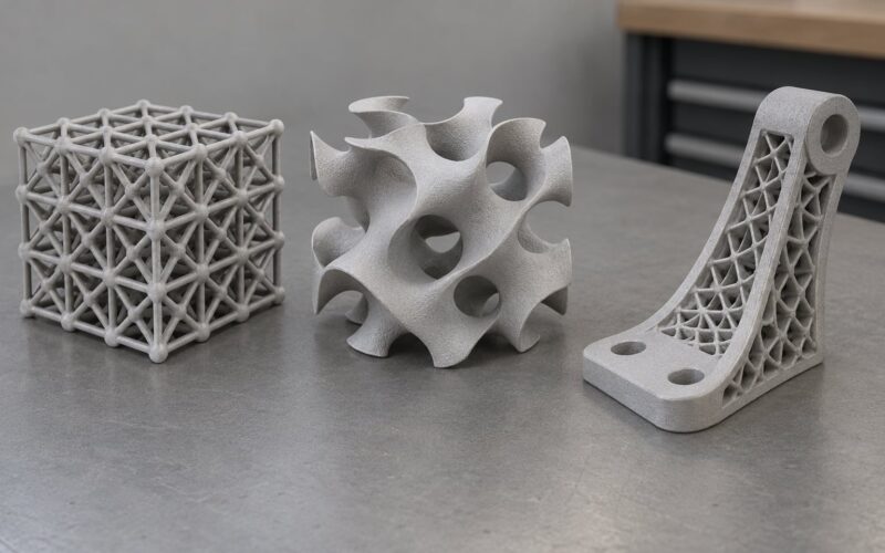
Walls and ribs. Most alloys want a minimum wall of about 0.5 to 1 mm, and thin walls print hot and warp. Instead of a solid block, designers use ribs and lattice infill, which cuts weight, cuts material use and lets residual stress relax instead of building up.
Overhangs and supports. Metal overhangs are generally better than about 45 degrees. Anything shallower needs support, and metal supports are expensive to remove, so the goal is to orient the part so fewer and simpler supports are required. Supports have three jobs: hold up geometry, conduct heat away from hot spots, and anchor the part to the platform.
Holes and channels. Small horizontal holes trap unsintered powder and are almost impossible to clear, so designers either enlarge the hole, tilt the part, or accept a machining operation. Internal channels and lattices are where metal printing beats everything else, though channel cross-sections usually need a teardrop or diamond shape to be printable at that scale.
Orientation. This is the single most consequential decision in the whole process. Orientation sets surface quality on the most visible faces, support count, trapped powder, distortion risk and fatigue behaviour along each axis. Spun and laser powder bed parts are usually strongest along the build direction, so critical loads are placed in-plane where possible.
Powder removal and machining stock. Design internal volumes that drain and can be cleaned, and leave a machining allowance on faces that need to be flat or dimensionally tight. Embossed text and logos should be raised rather than engraved, since engraved features fill with powder and blur.
Consolidation. A common move is to print an assembly as one piece: several brackets, or a bracket plus its fasteners, fused into a single part. This cuts assembly time and eliminates fastener failure points, and it is one of the clearest economic cases for metal printing.
What Are the Main Advantages and Limitations?
The upside is geometry. Metal printing can make internal channels, conformal cooling, lattices, consolidated assemblies and topology-optimised shapes that machining cannot reach and casting cannot fill. A mould insert with cooling passages running through every cavity wall is the textbook example, since no other process makes those passages cheaply. Add near-net shape, low tooling cost and low material waste, and the case is strong for low volumes of complex parts.
The limits are equally real. Cost per part is high, because machine time, powder and post-processing are all expensive, and because post-processing often outweighs the print itself. Throughput is low, so a production run of thousands of identical parts belongs in casting, forging or injection moulding. Build volume caps part size, usually to somewhere around 250 by 150 by 150 mm on lab machines, and larger parts mean nesting more parts per build or moving to DED.
Surface finish is another honest trade-off. As-built metal is rough, at Ra 6 to 10 microns, so visible surfaces and mating surfaces need machining or blasting. Fatigue strength is generally below that of a machined part of the same alloy because the as-built microstructure is columnar and interrupted by melt-pool boundaries, which matters most in aerospace and medical work where the standard is fatigue-critical qualification rather than a tensile test. Certification for load-bearing parts is the slowest hurdle of all: material process qualification and part qualification take time that a plastic prototype never requires.
Metal printing also competes with CNC machining, and the practical guidance is straightforward. Low volume and high complexity points to printing. High volume of simple parts points to machining. Very large parts and repair work point to DED. High volume of complex parts points to metal casting, with printing used for the pattern or the prototype.
One more comparison worth knowing, because it comes up constantly in machining shops: metal printing produces good static strength and modest fatigue strength, while CNC machining produces both. Veteran machinists are right to be sceptical, and the honest answer is that most printed metal parts end up partly machined anyway, which is why the process is often a hybrid rather than a replacement.
Frequently Asked Questions
Is metal 3D printing safe?
It is safe when handled properly, and it is not a garage hobby. Fine metal powder is an inhalation hazard, and aluminium and titanium powders can ignite when scattered in air. Industrial machines keep powder sealed, run local extraction, maintain oxygen below about 25 ppm with argon, and restrict access to trained operators. Desktop bound-powder systems reduce the risk but still need a ventilated room and a closed handling step.
What is the most common metal 3D printing process?
Powder bed fusion, and specifically laser powder bed fusion, is by far the most common. A fibre laser melts fine alloy powder spread across a build platform inside an argon chamber, layer by layer, with each new layer re-melting the previous one so the part bonds into a single solid. Electron beam melting is the second major variant, used mostly for titanium in aerospace and medical work.
Can metal 3D printers print at home?
A normal FDM or resin printer cannot print bare metal, but desktop bound-powder extrusion machines can. They extrude metal powder suspended in a polymer binder as a plastic-like filament, then the printed part goes through catalytic debinding and sintering to become fully metal. These machines are the realistic home option. They still cost several times a good plastic printer and need a sintering furnace, powder handling equipment and ventilation.
How accurate is metal 3D printing?
Laser powder bed fusion typically holds dimensional tolerance of about plus or minus 0.1 mm, with as-built surface roughness around Ra 6 to 10 microns. That is accurate enough for brackets, housings and many assemblies, but not for bearing bores or tight mating surfaces, which get machined afterwards. Designers who need both precision and complex geometry print with a machining allowance and finish the critical faces on a CNC machine.
Does metal 3D printing require support structures?
Usually, yes, and unlike plastic they cannot be dissolved or snapped off. They exist to hold up overhangs steeper than roughly 45 degrees, to conduct heat out of hot spots and to anchor the part to the build platform. Because they are the same metal as the part, they come off by wire EDM, water jet, bandsaw or CNC. Part orientation is chosen to minimise support count, since support removal is a major cost driver.
How much does a metal 3D printed part cost?
Cost depends far more on part size, post-processing and setup than on machine time alone. Industrial machines run well into six figures and multi-million dollar machines are common in aerospace. Depowdering, support removal, stress relief, heat treatment and machining together can cost more than the print itself, so a part that needs a lot of finishing is expensive even when the build itself is quick.
Where to Start
If you want to see it rather than read about it, the cheapest route is a print bureau: send a CAD file, pick a material, and get a real part back in a few days without buying a furnace. If you need geometry that no other process can make, start with a design-for-additive review of your part’s orientation and supports before anything reaches the machine, because those two decisions do more for cost and quality than any material choice.