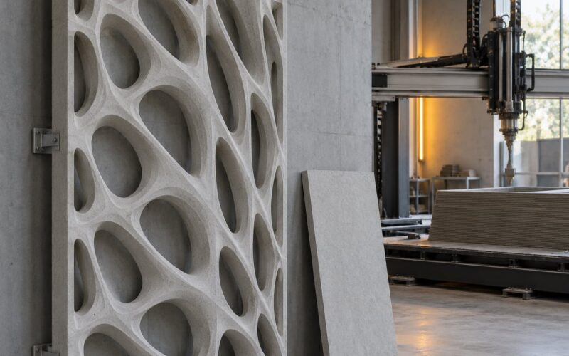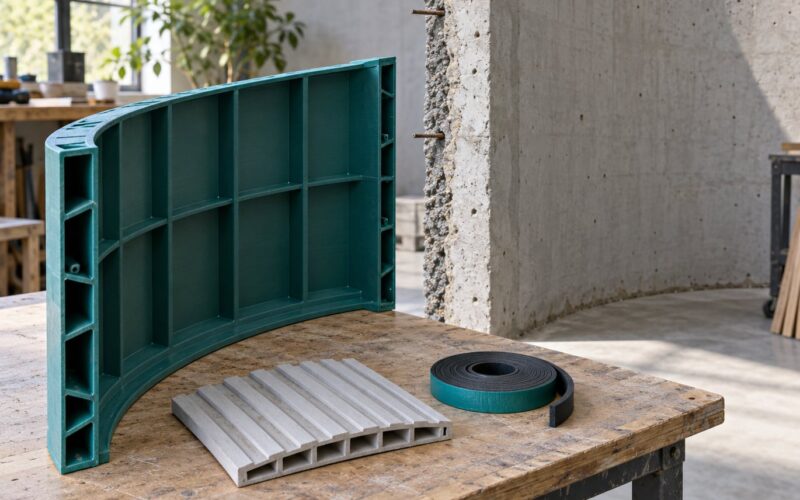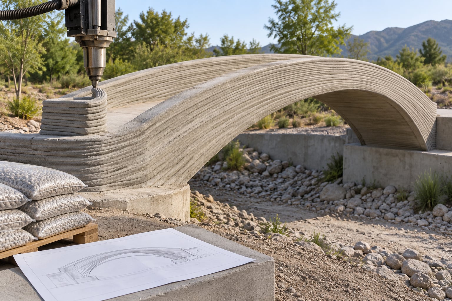
A 3D printed bridge is a load-bearing span built by a robotic arm or gantry printer that deposits concrete, steel or composite material bead by bead from a digital model, removing the molds and formwork normally needed for casting. Engineers work out how 3D printed bridges are engineered by defining the load path first, then constraining the geometry to what the printer can physically build, and only then proving the finished span with calculations and physical load tests.
That order matters. Printing changes how a bridge is shaped, not whether it has to obey the same structural rules as any other crossing.
Table of Contents
- How 3D Printed Bridges Are Engineered
- What Loads Must a 3D Printed Bridge Carry?
- How Is the Bridge Designed in 3D?
- What Materials Make Printed Bridges Strong?
- How Is a 3D Printed Bridge Reinforced?
- How Are Bridges Printed in Place?
- How Do Engineers Know a Printed Bridge Is Safe?
- What Are the Limits of 3D Printed Bridges?
- Frequently Asked Questions
- Are 3D printed bridges structurally safe?
- How do 3D printed concrete bridges resist tension?
- What material is used to 3D print bridges?
- How long can a 3D printed bridge span?
- Can 3D printing be used for full-scale road bridges?
- Conclusion
How 3D Printed Bridges Are Engineered
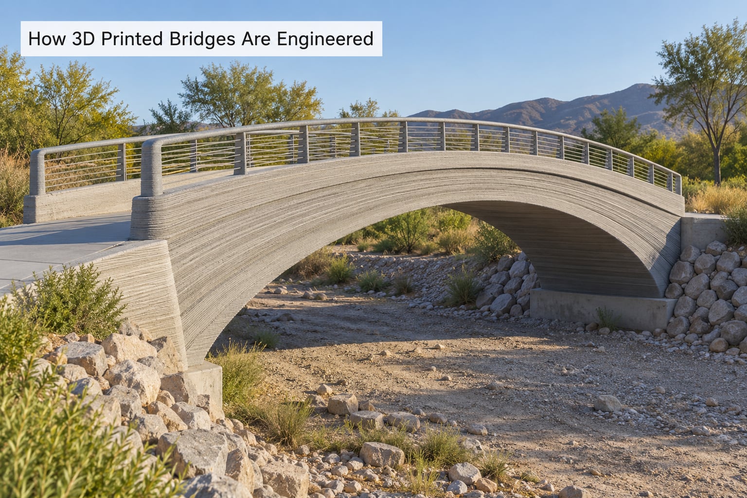
The engineering lifecycle has six stages, and each one can invalidate the next if it is skipped.
- Establish the brief and the site. Span length, clearances, soil conditions, water levels, heritage constraints and who will actually use the crossing. Foundation design follows directly from the ground survey here, not later.
- Build the digital structural model. Survey points and architectural geometry become a 3D model with real member thicknesses, supports, foundations and joints.
- Choose a printable material system. The mix or alloy has to flow through the nozzle, gain strength at a build rate the machine can match, and bond to the layer below.
- Design the load path. Every kilo of the bridge must be traceable to the ground. Form, geometry and internal voids follow from that tracing.
- Constrain the design for printing. Bead width, nozzle turning radius and the need for a continuous deposition path get folded back into the structural model as hard limits.
- Validate by analysis and testing. Finite-element checks, material coupon tests, print quality inspection and a physical load test before anyone walks on it.
Steps 4 and 5 are where printed bridges diverge most from conventional ones, and skipping either is the most common way a printed span ends up looking striking and structurally weak.
What Loads Must a 3D Printed Bridge Carry?
Every bridge carries more than the people on it. Design work starts by listing each load type, what part of the structure it stresses, and how it changes the design.
| Load type | What it does to the structure | Design consequence |
|---|---|---|
| Dead load | Weight of the printed structure, deck, finish, railings and any fixed services | Sets the baseline compression in every member and sizes the foundations |
| Pedestrian live load | Moving, unevenly distributed footfall, plus concentrated crowd loading | Drives bending in the deck and local punching forces under feet |
| Wind | Lateral push on the span, deck and any railing or screen | Requires lateral stiffness and bracing, and controls arch stability |
| Snow and ice | Additional dead load, sometimes uneven, plus a slippery surface | Raises compression and can create local loading where snow drifts |
| Thermal movement | Expansion and contraction of the printed material over seasons and sun exposure | Defines where bearings and movement joints go |
| Impact and vibration | Sudden or repeated dynamic loading, including footfall rhythm | Controls serviceability limits, not just ultimate strength |
| Construction-stage forces | Self-weight of partly cured material, print head reaction, temporary supports | Often the governing case during printing, before the bridge is complete |
Engineers never check these one at a time. Load combinations apply factors to several actions at once, following the governing bridge design standard, so the structure is checked against the most demanding realistic pairing rather than an artificial worst case.
Construction-stage loading deserves more attention than it gets in promotional coverage. Fresh material has almost no stiffness until it cures, so a long unsupported printed overhang can fail under its own weight while it is still being built.
How Is the Bridge Designed in 3D?
The design starts as survey data and a sketch of the required geometry, then becomes a model with structural depth. Survey control points define the alignment and the levels of the approaches, and the model carries those through to member thicknesses that can actually be extruded.
An arch and a beam behave very differently. An arch sends load almost entirely into compression, which plays to concrete’s strengths. A beam works in bending, which means the bottom fiber is in tension and needs reinforcement. Most pedestrian printed spans are designed in the arch family for exactly that reason.
Supports and foundations are modeled as real elements. A printed pier or abutment still transfers everything into soil or rock, and the ground conditions from the survey usually govern how much of the bridge can be printed at all.
Then come the fabrication limits, and they are not decoration. Bead width sets how fine the geometry can be. The nozzle has a turning radius, so tight corners and sharp inside corners either get rounded off or need a deliberate feature. The deposition path must stay continuous, which is why printed structures tend to follow sweeping, flowing curves rather than sharp orthogonal forms. Internal voids and hollow sections reduce dead load and material use, but they change how the load travels through the member.
Tolerances are set at the point where each layer and bead sits on the one below, because that interface is the weakest link in the whole structure. Movement joints get designed in from the start; retrofitting one into a finished printed shell is far harder.
Good practice is to run structural analysis and print simulation side by side. A model that passes stress checks but whose toolpath cannot be deposited without voids or supports is not a buildable bridge, whatever the analysis says.
What Materials Make Printed Bridges Strong?
Material choice is a negotiation between what the structure needs, what the printer can extrude, and how fast the material gains strength. Compressive strength gets the attention, but tensile behaviour decides whether reinforcement is needed.
| Material system | Compression | Tension | Printability | Typical structural role |
|---|---|---|---|---|
| Engineered cementitious mix (3DCP) | High; the main strength selling point | Very weak; governs design | Good with a tuned rheology, no formwork needed | Compression-only arches, abutments, walls, decks |
| Fibre-reinforced cementitious mix | High | Improved by short fibres bridging microcracks | Good, if fibres do not clog the nozzle | Reducing crack width in deck and spandrel elements |
| Polymer or composite beams | Low relative to concrete | Good | Very good on smaller printers | Formwork, moulds, non-load-bearing elements, prototypes |
| Printed steel (WAAM or directed energy deposition) | Good; allows slender members | Excellent; steel resists tension | Demanding; heat management and interlayer control | Whole structural frames including tension members |
One point gets lost too often. A strong test cube does not prove bridge performance. Compression tests on small specimens cannot capture the layer bond, the real member geometry, the print defects or how the structure behaves as a system under a moving load.
Interlayer bond strength is the property to watch. If the bond between layers is weaker than the material within a layer, the structure behaves less like a solid monolith and more like a stack of blocks that happen to be stuck together.
How Is a 3D Printed Bridge Reinforced?
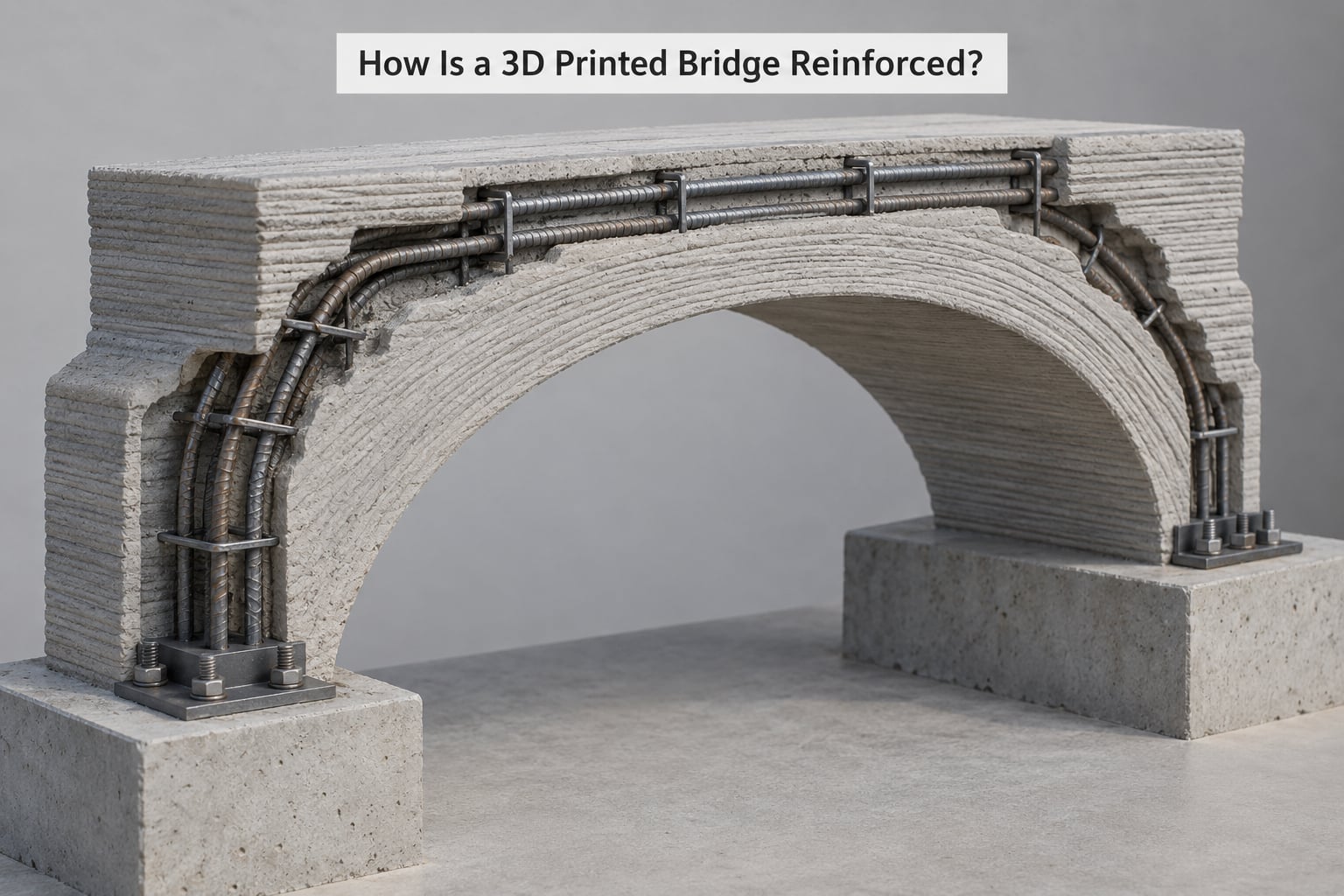
Printed concrete resists compression well and tension very poorly, so reinforcement is not optional. In a r/StructuralEngineering discussion, commenters were blunt about the assumption that printed walls contain no steel, and the assumption is wrong in most real projects.
The main reinforcement strategies are post-tensioned cables, conventional steel bars placed in ducts or reserved channels, prefabricated reinforcement cages dropped into place, engineered fibres in the mix, and hybrid structures where the printed shell works with steel or conventional concrete members. Anchors and bearing plates transfer force from the printed body into steel or into the foundations.
Each route has a cost. Post-tensioning adds a stressing step and hardware but gives a printed span real bending capacity. Embedded bars mean planning cavities and handling steel in a wet print environment. Fibres are easy to print but cannot carry major tension on their own.
Researchers at MIT have described feeding rebar into printed concrete as a challenge that is still proving itself. That single sentence explains why so many demonstration spans stay in the compression-only arch family instead.
The load path is straightforward to describe: a pedestrian’s weight lands on the printed deck, travels along the deck slab into the arch ribs, passes through the arch into the abutments, and finally spreads into the foundations and the ground. Any point in that chain where tension appears needs steel, post-tensioning or a geometry that removes the tension.
How Are Bridges Printed in Place?
Site work runs in a fixed order, and the early steps decide whether the print succeeds. The ground is prepared and levelled, then foundations are cast or printed, giving the machine a stable base to work from. Supports, abutments or temporary falsework go up before anything is extruded overhead.
Then the machine is calibrated. Extrusion rate and layer height are set against the mix, the nozzle is checked, and a test deposit confirms the bead profile and adhesion to the previous layer. Printing begins and moves continuously along the toolpath, which is why the toolpath itself is an engineering deliverable rather than a software detail.
During printing, quality control happens on the fly. Large machines have cameras or scanners watching layer geometry, and interrupted prints can leave visible cold joints that need grinding and rewetting before the next layer goes down. Some large prints also interleave machining operations to create bolt holes, sensor channels or cable routes that could not be printed.
After deposition, curing is not optional and rarely fast. The structure may sit under cover or with its formwork-like outer shells in place while it gains strength. Reinforcement installation, deck finishing, waterproofing, then bearings, joints and railings follow.
Temporary supports usually stay until the printed structure reaches sufficient strength to carry itself. Where the print has to pause overnight, those supports bridge the gap. The Autodesk bridge documented with roughly 24 km of toolpath used infill geometry and temporary stands for exactly this reason, with infrared heat lamps restoring bond strength after in-process milling.
How Do Engineers Know a Printed Bridge Is Safe?
Safety is demonstrated in a sequence, and visual inspection alone cannot establish safe load capacity. It tells you about surface condition, nothing about the load path.
- Structural calculations. Hand checks and computer analysis of every load combination in the governing code.
- Finite-element analysis. A full model showing stress, deflection, buckling and how load spreads from deck to foundations.
- Material characterization. Tests on the actual mix or alloy, including compression, tension, adhesion and durability in the printed direction.
- Coupon and component tests. Printed samples and sub-assemblies pulled apart to find the weak link before the full structure carries anything.
- Print quality inspection. Layer dimensions, voids, cold joints and deviations from the model, checked against tolerances.
- Load testing. The finished span is loaded in increments, with strain and deflection measured throughout.
- Code and standards review. An independent check against the bridge design standard the jurisdiction applies.
- Post-installation inspection. Monitoring after opening, and often a sensor network feeding a digital twin.
The published MIT result is a useful illustration of what a real test looks like. A printed concrete bridge about 2.3 metres long, weighing roughly 900 lb, held more than 2,000 lb with negligible deflection. The same structure failed when a corner was lifted, because that put the concrete into tension. One test, two results, and the second one explains the entire design philosophy.
What Are the Limits of 3D Printed Bridges?
Being honest about the limits is more useful than the hype, and engineers working in this field are open about them.
- Anisotropy. Material properties differ between layers and along the deposition direction, so a printed member is not the same thing in every direction.
- Nozzle variability. Output depends on mix consistency, pump condition, ambient temperature and speed. A well-behaved test deposit does not guarantee a well-behaved print on day nine.
- Limited tensile capacity. The core weakness of printed concrete, and the reason reinforcement decides the achievable span.
- Surface finish. Layer lines and seams are visible, which matters in heritage settings and means fair-faced finishes need post-processing.
- Joint and reinforcement challenges. Cables, bars and ducts have to be planned into the model and placed into a wet, moving structure.
- Print time at full scale. Large spans take days of deposition, often with pauses, weather exposure and inspection hold points along the way.
- Code acceptance. Printed structures still need approval from an authority that has a code written for cast and conventionally fabricated work.
- Repairability and inspection. Local defects are harder to assess and patch in a layered shell than in a conventional member.
This is why the process is most compelling for bespoke geometry. A bridge with complex curves, an irregular site or constrained access is expensive to form in timber or steel, and printing places material only where loads need it. Straight, repetitive, equal-span work is still cheaper the conventional way.
Frequently Asked Questions
Are 3D printed bridges structurally safe?
Yes, when they follow the same engineering discipline as any other bridge: a defined load path, a validated material system, real reinforcement where tension occurs, and documented load testing before opening. A published MIT test held more than 2,000 lb on a roughly 900 lb printed span with negligible deflection. Safety comes from that chain of evidence, not from the printing process itself.
How do 3D printed concrete bridges resist tension?
They resist tension through reinforcement rather than through the printed material. Engineers use post-tensioned cables, steel bars in reserved channels, prefabricated cages, engineered fibres in the mix, or hybrid steel members, and often combine these. Alternatively the geometry is shaped into a compression-only arch so that tension never develops in the concrete.
What material is used to 3D print bridges?
Most full-scale printed bridges use engineered cementitious mixes extruded by gantry or robotic arm printers. Some use fibre-reinforced mixes to control cracking. Printed steel through wire arc additive manufacturing or directed energy deposition is also used, and it handles tension well. Polymer composites appear mainly in formwork, prototypes and small structures.
How long can a 3D printed bridge span?
Span is limited by tensile capacity, reinforcement strategy and print time rather than by the printer alone. Pedestrian arches in the several-metre range are routine, and longer demonstration spans have been built. Longer spans push harder on deflection, arch stability and curing time, so spans grow mainly where post-tensioning or printed steel carries the tension.
Can 3D printing be used for full-scale road bridges?
Technically the process works for full-scale road bridges, and several have been built and proof tested, but it remains unusual. Code acceptance, vehicle load modelling, fatigue and impact requirements, surface durability and inspection of large printed members all add difficulty. Most deployed printed structures remain pedestrian bridges, canal crossings and disaster relief spans.
Conclusion
How 3D printed bridges are engineered comes down to one chain: a load path defined before any geometry exists, a material system tested in the direction it was printed, reinforcement wherever tension shows up, and a finished span proven by analysis and physical load test. Printing removes formwork and places material where it earns its keep, but it changes none of those obligations.
So when you read about a printed bridge, check four things before anything else. Is the load path stated and traceable to the foundations? Was the printed material characterised, including the layer bond? Is the reinforcement strategy named? And is there a documented proof load with deflection figures, rather than a photo of a finished span? Projects that answer all four are worth paying attention to. The ones that show only the finished bridge are selling you the picture, not the engineering.