Designing a case for a Raspberry Pi means building an enclosure around one specific board: its mounting holes, port layout, connector heights, and whatever HAT, heatsink or cooler is stacked on top. You model that shell once, then print, laser cut or fabricate it. This guide walks the whole job in order, from measuring your board to test-fitting the result before you commit to a full print. It covers Pi Zero and Zero 2 W through Pi 5, and works in Fusion 360, Onshape, Shapr3D, FreeCAD, OpenSCAD or Tinkercad.
The bit that catches beginners out is not the modelling. It is tolerance. A case that is dimensionally perfect on screen still has to fit a part made by a printer that varies by a few hundredths of a millimetre, so almost every decision below comes back to clearance, support and test prints.
Table of Contents
- What You Need Before You Design a Case for a Raspberry Pi
- Step-by-Step
- How to Design a Case for a Raspberry Pi with the Right Dimensions
- Create the Base and Board Support
- Model the Port and Connector Cutouts
- Add Cooling, Ventilation, and Cable Management
- Check Fit, Printability, and Assembly
- Common Mistakes
- Frequently Asked Questions
- What is the best software for designing a Raspberry Pi case?
- How much clearance should I leave around Raspberry Pi ports?
- Should a Raspberry Pi case have ventilation or a fan?
- Can one 3D-printed case fit different Raspberry Pi models?
- How do I make a Raspberry Pi case easy to assemble?
- Do Raspberry Pi cases need access to the GPIO pins?
What You Need Before You Design a Case for a Raspberry Pi
Start by pinning down exactly which board is going inside. A 3B, 4 and 5 share a 85 by 56 mm outline, but they differ in component height, port arrangement and what sits on the underside, and a case designed for one will not drop into the next.
- The exact board and revision. Note the model printed on the board, plus anything stacked on it: an HAT, a camera ribbon, a heatsink, an Active Cooler.
- A reference model or drawing. Community STEP files of Pi boards exist on model-sharing libraries, and Raspberry Pi publishes mechanical drawings. Download whichever matches your revision.
- A caliper and reference photos. A 0.01 mm digital caliper for the fallback measurement pass, plus clear photos of both faces of the board.
- CAD software. Anything that can import a STEP file and do a shell operation works. Tinkercad and FreeCAD are free, Shapr3D and Fusion 360 are easier for surface-modelled snaps.
- A slicer and a printer. PrusaSlicer or OrcaSlicer, and a machine you have already calibrated, because tolerance advice is meaningless without knowing your XY offset.
- Filament. PLA prints crisply and snaps arms break easily. PETG and ABS are tougher; nylon is tough and dimensionally stable but fussy to print.
- Optional hardware. M2.5 or M3 standoffs and screws, heat-set inserts, rubber feet, a 30 mm or 40 mm fan, a heatsink, an LED window.
None of this is expensive. The only item worth spending real care on is the reference geometry, because every dimension you cut later inherits its accuracy.
Step-by-Step
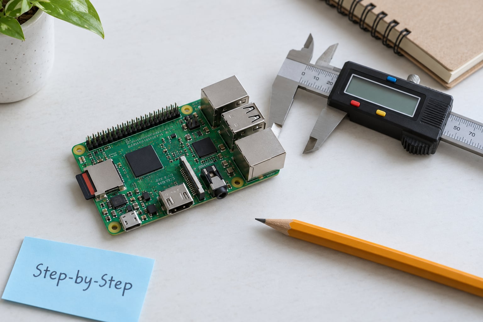
How to Design a Case for a Raspberry Pi with the Right Dimensions
Take every dimension from the exact board revision in your hands, not from a diagram. The outline, the mounting hole positions, the connector centres and the tallest components are the only numbers that matter, and each one changes between generations.
Record the board outline first. Full-size boards are 85 by 56 mm and the Zero and Zero 2 W are 65 by 30 mm. Then measure component heights around the edges: full-size boards carry parts close to 10 mm tall in places, and the Pi 5 adds a power button, a fan header, an RTC battery connector and a PCIe ribbon connector on top of what earlier boards had.
Mounting holes are the feature most people get wrong. Full-size boards use four holes at 58 by 49 mm centres; the Zero boards have a much smaller pattern with two holes near one edge, so size the boss from your own measurement rather than from a memory of the big board.
| Board | Board size (mm) | Mounting holes | What changes for the case |
|---|---|---|---|
| Pi Zero / Zero W | 65 x 30 | Two small holes near one edge | Mini-HDMI, micro-USB power and data, unpopulated 40-pin header |
| Pi Zero 2 W | 65 x 30 | Same outline as the Zero | Same port set as the Zero; keep a camera connector variant in mind |
| Pi 3 / 3B+ | 85 x 56 | Four holes, 58 x 49 mm centres | Full-size USB-A stack, Ethernet, 40-pin header along one long edge |
| Pi 4 | 85 x 56 | Four holes, 58 x 49 mm centres | Two micro-HDMI ports close together, microSD slot on the underside |
| Pi 5 | 85 x 56 | Four holes, 58 x 49 mm centres | USB-C power, PCIe ribbon connector, fan and battery headers, extra top-side height for an Active Cooler |
Now decide your clearance number once and apply it everywhere. For a general friction fit, makers in r/3Dprinting commonly work between 0.15 mm and 0.25 mm per side. Designers who model Pi cases specifically tend to leave more, around 0.6 mm of material around the board and its standoffs, because the board has to be captured while the shell still assembles. Pick a figure, write it into a parameter, and stop second-guessing it mid-model.
Create the Base and Board Support
A good case starts as a solid block and loses material. Sketch the footprint of your board on a construction plane near the top of that block, extrude the outer walls upward, fillet the outer vertical corners generously for looks and handling, then shell the result to a wall thickness of about 2 to 3 mm.
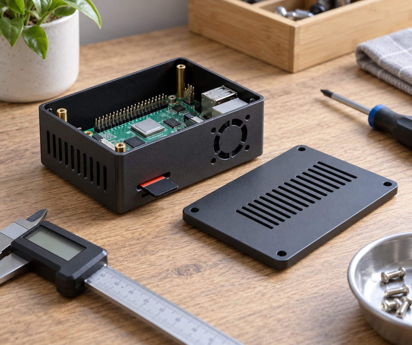
Board support matters more than the shell. Project the board’s mounting holes down onto the base and grow a boss around each one, sizing the boss so the screw head or standoff drops into it without touching the board. On a full-size board that means four bosses roughly 4.5 mm across at the hole pattern, and a pilot hole down the middle for the standoff or a heat-set insert.
Four corner bosses on their own leave the middle of the PCB unsupported, and that is the most common reason a board cracks or rattles inside a case. Add a low pad or rib under the centre of the board so it lands on something, and make that support about 0.4 mm lower than the standoff shoulder so the board sits on the standoffs first.
Split the body on a midplane so you get a lid and a base, then check that nothing critical sits on the cut line. Two tall, thin walls crossing that plane create long bridging spans that lift on the print bed; a split down the middle of a board footprint is the usual culprit.
Model the Port and Connector Cutouts
Cut openings for the plug, not for the connector. The metal shell on a USB port is small, but the plastic housing around the plug is wider, taller and often angled, and that housing is what actually hits your case wall.
| Port | Typical opening | What to watch |
|---|---|---|
| USB-A (Pi 4, Pi 5) | About 13 x 15 mm plus 1 mm | Plug housing and strain relief sit wider than the metal shell |
| USB-C power (Pi 4, Pi 5) | Rounded slot, about 9 x 5 mm plus 1 mm | Modern USB-C plugs are chunky and pull straight out along the board edge |
| micro-USB power (Pi 3, Zero) | About 8 x 5 mm plus 1 mm | Angled insertion; leave room for the cable to leave the case sideways |
| micro-HDMI | About 9 x 4 mm plus 1 mm | Two of them sit close together on Pi 4 and Pi 5; a shared slot blocks one cable |
| Ethernet RJ45 | About 17 mm wide, latch clearance above | The socket body is deep and the latch needs room to swing |
| 3.5 mm audio jack | About 9 mm across | Plug barrel plus the knuckle on the end of the cable |
| microSD slot | Slot on the underside, overhang the lip by 2 mm | The card protrudes and inserts at an angle; round the entry edge |
| 40-pin GPIO header | Full length opening, or a removable lid | Jumper wires need somewhere to go |
| Pi 5 PCIe, fan and battery headers | Small slots with a hinged cover | Ribbon cables bend tightly; a lost cover is a lost connector |
Build these as extruded cuts straight through the wall, and derive them from the imported reference model where you can. Tracing or projecting the connector geometry off the STEP file beats typing numbers in, and chamfer the opening edges by about 1 mm so plugs slide in without scraping the print.
Leave the board free to be inserted after the case is closed wherever the layout allows it. A design that only assembles with the board already threaded through the ports will fight you every time you open it.
Add Cooling, Ventilation, and Cable Management
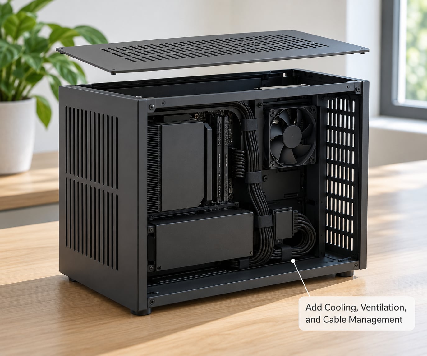
Put the vents over the processor, not just somewhere on the board. Which face it sits on changes between models, so check your own board: on the Pi 4 the chip and its heatsink are on the underside, and on the Pi 5 the Active Cooler mounts on top. A lid full of slots above a bottom-mounted chip does very little.
A vertical slot pattern works better than a grid of small holes. Slots print faster at the same open area, they are easier to clean, and if you zig-zag them they also give a snap-fit lid enough flex to snap on without a separate spring feature.
For active cooling, model a 30 mm or 40 mm fan cutout with a matching grille and duct the airflow straight onto the chip. If you plan to use the Pi 5 Active Cooler, give it dedicated clearance above the board and keep the lid off the connector, because that cooler and its ribbon are the tightest vertical stack on the current board.
Cable management is what people notice after a month of use. Route power along an interior wall with a channel deep enough that a plugged-in cable is not bent at a hard right angle, add ribs where a cable enters the case, and split the case so it opens without dragging wires. Where you need the GPIO header, cut it open fully or add a hinged cover instead of leaving it buried.
Check Fit, Printability, and Assembly
Before slicing, check that the model prints cleanly on your machine. Vertical walls of 2 to 3 mm print as strong perimeters; anything much thinner bows between layers, and the long flat faces over port cutouts and vent fields are where you will see it first.
Keep overhangs at or under 45 degrees, or add a small chamfer so the printer bridges the transition. A cantilever snap arm is the classic failure: give the arm a generous root, taper it toward the hook, and add a 0.6 to 1 mm chamfer at the base so it prints without supports and stays attached layer to layer.
Then print a test fit instead of gambling a whole case. Print a shallow base section with the standoffs and the port cutouts, about 10 mm tall, and try the real board in it with real cables attached. Twenty minutes of filament tells you whether your standoff diameters and your clearance number are right before you print anything else.
For assembly, decide how you want to get in and out of the case. Screw bosses are the most reliable and the easiest to repair, snap-fits are tidier and need no tools but have to survive your printer’s tolerance, and stacked plates are the answer when you want to reach the board without undoing anything.
Common Mistakes
Almost every failed Pi case comes down to one of a small number of things. The fixes below are the ones that come up repeatedly in maker communities.
| Fit type | Clearance per side | Typical symptom when you get it wrong |
|---|---|---|
| Snug friction fit | 0.10 to 0.20 mm | Cracking on assembly on a printer that runs slightly under size |
| General sliding fit | 0.15 to 0.25 mm | A visible gap in the model that closes on the printed part |
| Board to standoff capture | Around 0.6 mm | Board rocks, or holes never line up because the boss is too fat |
| Snap-fit arm (hook to catch) | 0.20 to 0.30 mm | Hook snaps off, or the lid never engages at all |
- Wrong board revision. Fix: print the model number off the board and re-measure before cutting anything.
- Port cutouts sized to the connector instead of the plug. Fix: model the plug from the reference file, then add 1 mm.
- microSD slot too small. Fix: overhang the card lip by 2 mm and round the entry corner.
- No centre support under the board. Fix: add a low pad under the middle so the PCB cannot flex.
- Snap arms breaking in PLA. Fix: widen the arm root, chamfer the base, or switch to PETG.
- Supports in awkward places. Fix: reorient the snap arms so each one prints at 45 degrees or less.
- GPIO header buried. Fix: open the header fully or add a hinged lid.
- No vents, or vents in the wrong place. Fix: find the chip on your board, then vent that face.
- Ignoring cable bend radius. Fix: add a channel so a plugged-in cable runs straight for a centimetre or two.
- Tolerances designed before calibration. Fix: print a 20 mm dimension check, measure it, and adjust your XY offset before the test fit.
Frequently Asked Questions
What is the best software for designing a Raspberry Pi case?
Fusion 360 and Shapr3D handle surface-modelled snap fits best and both are easy to learn, with Shapr3D limited to iPad and Mac. Onshape runs in a browser and has a usable free plan, which suits people who do not want to install anything. FreeCAD and OpenSCAD are free and open source, though OpenSCAD works in code rather than clicks. Tinkercad is free and fine for a first box, but its fillet and shell tools are too limited for a proper snap-fit.
How much clearance should I leave around Raspberry Pi ports?
Leave about 0.15 to 0.25 mm per side for a general sliding fit, and add roughly 1 mm around the opening itself so the plug housing clears the wall. Measure the plug itself rather than the metal connector shell, since the housing is wider. If your board rocks once it is inside, the standoff bosses are too fat, not the ports too tight.
Should a Raspberry Pi case have ventilation or a fan?
Vent it in every case. A solid box traps the processor’s heat and the board will throttle or shut down under sustained load, and slots cost nothing to print. A fan only matters when the board is running hard, such as in a NAS or a video decode box. If you do add one, duct it toward the chip on whichever face the board uses, and give an Active Cooler on a Pi 5 enough headroom above the board.
Can one 3D-printed case fit different Raspberry Pi models?
Only with a parametric design and loose tolerances, so plan for partial compatibility rather than a single perfect fit. Pi 3, 3B+, 4 and 5 share an 85 x 56 mm outline and the same 58 x 49 mm mounting pattern, so one base can hold several of them. The differences are port positions, component height and extra connectors on the Pi 5, so make the port pattern and lid height switchable parameters rather than cutting them into the model.
How do I make a Raspberry Pi case easy to assemble?
Give the two halves an alignment feature, such as a shallow ridge and matching groove, so they self-centre instead of needing to be pushed together at an angle. Add a finger scoop opposite each snap arm, chamfer the edges so nothing catches, and prefer screw bosses over snaps if you will open the case often. Print a shallow test section and assemble it a few times before committing to the full case.
Do Raspberry Pi cases need access to the GPIO pins?
Only if your project uses them, and that decision changes the layout entirely. Leaving the 40-pin header open is the safe default, since jumper wires on a buried header are painful to attach. If your build needs the space, cut the header area out fully or add a hinged cover on the lid. Whichever you choose, tell yourself early, because adding access afterwards means remodelling the split line and the port cutouts.
Start where the plan says: pull a reference model for your exact board, then print a 10 mm test section with the standoffs and port cutouts in it before modelling anything else. Most cases that need a fifth print failed that test. Get the fit right first, then add vents, ribs and a lid, and write your clearance into a parameter so the next board revision is a one-number change rather than a new project.