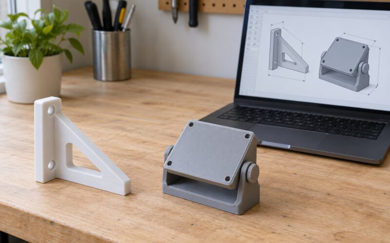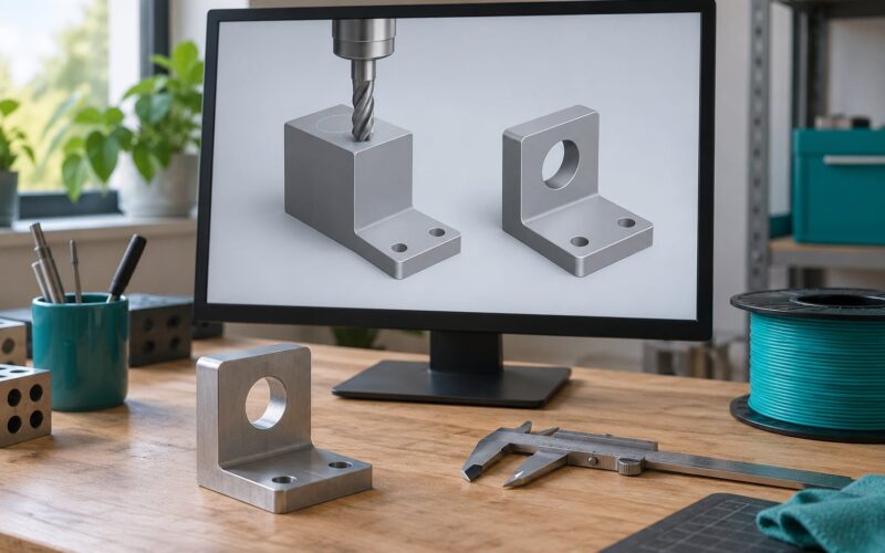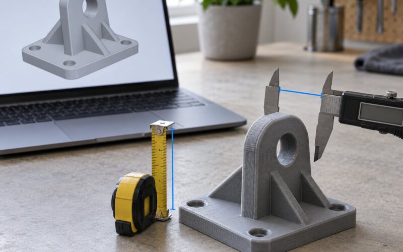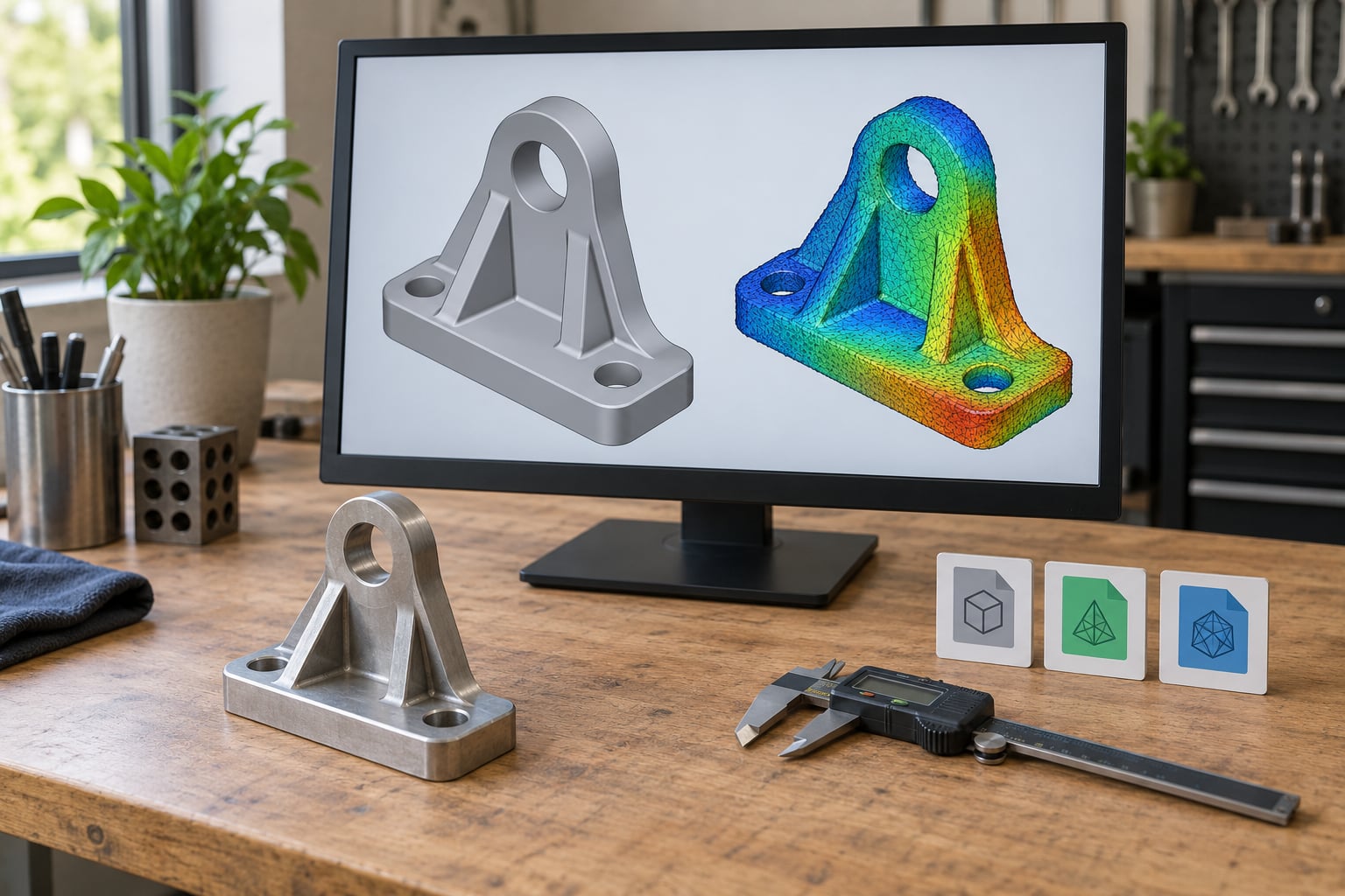
Turning a 3D scan into a CAD model is reverse engineering, not a file conversion. A scanner hands you millions of surface points wrapped into a triangle mesh, and that mesh can be printed but not dimensioned, edited or machined. To get a real CAD model you import the scan, align it, clean it, fit geometry to it, and rebuild the part as parametric features you can change later.
The confusing part is that the conversion only runs one way. STEP and IGES files turn into STL all day long, but you cannot press a button and get an editable solid back out of an STL. It is the same problem as a PDF and a Word document: the PDF looks right, but you cannot click into it and change the paragraph spacing.
So if you have ever asked how to turn a 3D scan into a CAD model, the honest answer is that you are doing engineering work, not file plumbing. A simple machined bracket takes an hour or two of careful feature work. A worn mould insert with free-form surfaces can eat a full week. Knowing which job you have in front of you is the difference between a satisfying afternoon and a scrapped subscription.
Table of Contents
- What You Need
- Step-by-Step: How to Turn a 3D Scan Into a CAD Model
- Step 1: Import and inspect the 3D scan
- Step 2: Clean and align the scan data
- Step 3: Decide between a mesh, surface, and solid CAD model
- Step 4: Create or fit surfaces around the scan
- Step 5: Convert the surfaces into a solid CAD model
- Step 6: Validate and export the CAD model
- Common mistakes
- Frequently Asked Questions
- What is the best software for converting 3D scans to CAD models?
- Can I convert an STL file directly into a STEP file?
- How long does it take to convert a 3D scan to a CAD model?
- What is the best CAD file format for 3D printing?
- Do I need CAD software if I already have a 3D scanner?
- Can ChatGPT or AI make a CAD model from a 3D scan?
- Conclusion
What You Need
You need four things: the scan data itself, a cleanup tool, a reconstruction tool, and a way to check the finished model against the real part. The last one is the step people skip, and it is the step that catches a bad scale factor before you machine a bracket from it.
Start with the scan file. Handheld and desktop scanners usually export STL, OBJ, PLY or 3MF, and professional packages like Artec Studio or Creaform.OS keep their own project format. A point cloud with no colour and no baked-in texture is a perfectly good starting point. What matters is that the units and scale are known, which is a detail worth confirming before anything else.
Then decide what the finished file has to do, because that single choice drives every tool decision downstream.
| What you need out the other end | Best for | Skip the CAD rebuild? |
|---|---|---|
| Print-ready mesh | Broken part reproduced as a printed replacement, form checks, visual comparison | Yes, print the cleaned STL directly |
| Surface model (NURBS) | Free-form parts, styling surfaces, tooling that a CAM system can follow | No, but no feature history either |
| Parametric solid | Machining, design changes, toleranced drawings, anything that will be revised later | No, this is the full workflow |
| Inspection report | Comparing a manufactured part against the original CAD | No CAD model needed at all, use the scanner’s compare tool |
| 2D drawing or DXF | Section views, plate profiles, workshop drawings | Partly, you can trace sections from the mesh |
For software, here is how the tiers stack up. Plenty of people ask on forums whether this can be done free, and the short answer is yes, with more manual work.
| Tier | Tools | Good at | Weak at |
|---|---|---|---|
| Free and open source | CloudCompare, MeshLab, FreeCAD, Blender | Mesh cleanup, alignment, decimation, hole filling, surfacing, and a fully parametric rebuild in FreeCAD | Automatic feature extraction. You do the fit by hand |
| Free for personal use | Autodesk Fusion 360 personal licence, SOLIDWORKS xDesign or Go small-team options | Mesh import as reference geometry, ScanTo3D style surfacing, solid modelling | Licensing terms change, so check what you are allowed to use commercially |
| Mid-range | QUICKSURFACE, EXModel, Xtract3D, Peel.CAD Pro | Auto-surface with edge loops, bridging scan and CAD, good value for small shops | Slower than the pro suites on large assemblies |
| Professional | Geomagic Design X, PolyWorks Modeler, Artec Studio, Autodesk Inventor | Automatic plane, cylinder and fillet detection on messy real-world parts, deviation reports | Cost, and a genuine learning curve |
Hardware matters less than people expect. A modern laptop with 16 GB of RAM will handle a several-million-triangle scan, but dense files get sluggish fast, and a tablet will not. You also want a digital caliper, and access to a coordinate measuring machine for parts where tolerance actually matters. A mouse rather than a trackpad helps when you are picking entities off a surface.
Finally, prepare the part. Clean off grease, loose paint and heavy rust, and set it on a matte surface. Scanning a dirty part puts the dirt in the mesh, and you will spend twenty minutes deleting geometry that was never the part. If a feature is damaged and you need it intact, mask it rather than trying to repair the scan later.
Step-by-Step: How to Turn a 3D Scan Into a CAD Model
Here is the whole workflow in order. Capture the object, clean and align the scan, decide which CAD path you are taking, fit geometry to the surface, rebuild the solid, then validate and export. Each step has a checkpoint, and if the checkpoint fails you go back rather than push forward and hope.
- Capture the object and export as mesh or point cloud, confirming the units and the scale.
- Clean and align by removing isolated geometry, filling holes, controlling triangle density, and registering the scan to a coordinate system.
- Choose the CAD path: visual mesh, surface model, or full parametric reconstruction.
- Extract features or fit surfaces by detecting planes, cylinders and fillets, or auto-surfacing the free-form areas.
- Rebuild the parametric model with sketches, constraints, extrudes, revolves and cuts so the part can be edited.
- Validate against the scan using a deviation comparison and real measurements, then export STEP, IGES, DXF or STL for the next tool.
Step 1: Import and inspect the 3D scan
Open the scan in a cleanup tool before you open it in CAD. CloudCompare and MeshLab both load STL, OBJ and PLY directly, and FreeCAD imports them through the Mesh workbench. A professional scan project loads into its own package, where you can see the raw registrations.
Check five things. Units and scale first, because a millimetre file imported as inches ends up 25 times too big and you will not spot it until the print. Then look at density: a scan with triangles wildly varying in size will behave badly under smoothing. Look for holes where the scanner lost track, usually deep bores and dark cavities. Look for floating debris near the object, usually a piece of the table. And look at the coordinate orientation, which is almost never what you want yet.
The checkpoint: the object should sit near the origin, roughly the size you expect, and have no obviously missing regions. If a hole is a real design feature like a bolt bore, leave it. If it is scanner drop-out, you fill it later.
Step 2: Clean and align the scan data
Cleaning is where scan files go to die, usually because people over-clean. Do the destructive operations in this order and save a copy before each one.
First, separate the part from the debris: connected-component selection in CloudCompare or MeshLab, then delete everything that is not the largest blob. Second, remove duplicate and degenerate faces. Third, fill holes, with a small radius for real design holes and a larger radius for drop-out.
Fourth, decimate. A ten-million-triangle scan is not more accurate than a two-million-triangle one if both are finer than your tolerance, and the smaller file is far easier to work with. Reduce gradually, checking a sharp edge before and after. Over-smoothing is the single most common ruined scan: the corners round off, a 2 mm fillet turns into a 3 mm blob, and the model no longer describes the part.
Fifth, align. If you took several scans, register them to each other first, then align the combined result to a best-fit coordinate system. Many scanners output global coordinates, but if yours is a handheld, you have to define the datum yourself: three planar faces, or two planes plus a cylinder.
The checkpoint: compare the cleaned mesh to the original with a deviation map. Anything beyond your process tolerance should be a deliberate decision, not a surprise. Also check a known dimension with calipers. A surprising number of alignment problems are really scale problems wearing a disguise.
Step 3: Decide between a mesh, surface, and solid CAD model
This is the fork that determines your hours. A mesh is what you already have. A surface model is fitted NURBS geometry with no design history, useful for styling and for CAM that accepts surfaces. A parametric solid is planes, holes, fillets and sketches with a feature tree, and it is the only one you can dimension, revise and hand to a machinist as an engineering deliverable.
Prismatic parts, which are most machined parts, are flat plates and blocks with holes, slots, steps and fillets. Those go to a solid fast, because every feature maps to a sketch and an extrude. Free-form parts, like moulds, turbine blades and body panels, have curved surfaces with no simple geometry underneath. Those usually want an auto-surface pass first, then a hybrid solid built on the fitted surfaces.
Practitioners on the SolidWorks and 3D scanning forums mostly land on the same answer for prismatic work: extract the entities, take section profiles through the mesh, and rebuild the features by hand using the scan as background reference. That route is slower than one-click automation and far more trustworthy.
Check with two questions. Will this part be revised after machining starts? And does it need a toleranced drawing? If yes to either, you need a parametric solid, and there is no shortcut to that.
Step 4: Create or fit surfaces around the scan
Entity extraction is the highest-value step for machined parts. Software in the Design X and Xtract3D class scans the mesh for planar regions, cylinders, cones, spheres and toroids, fits exact geometry, and snaps the matches together. If the part has four bolt holes, you get four controlled cylinders with real diameters rather than four ragged polygons.
Set a fit tolerance you can defend. Snapping a feature to the scan when the scan has 0.1 mm noise means your model inherits that noise. Fit slightly inside the measured surface, and let the deviation report tell you what you gave up.
For the free-form areas, take cross-sections through the mesh at regular intervals and fit a NURBS surface through those section curves. Loft or patch from the curves, then trim back to the edges where the fitted entities already exist. Keep sharp edges, holes and fillet boundaries as fitted geometry wherever possible, because surfacing across them rounds them off.
The checkpoint: section the fitted result and overlay it on the mesh section. A clean trace that sits on the mesh, with no wobble, is the goal. Deviation should be inside your tolerance band almost everywhere, with the only outliers on surfaces that were damaged when the part was built.
Step 5: Convert the surfaces into a solid CAD model
At this point you have geometry that looks right but is still not a solid. Stitching or knitting joins the fitted surfaces into one shell, healing closes the small gaps, and the shell becomes a BREP solid. Check for self-intersections, tiny slivers and open edges before you go further, because those become the errors that pop up three steps later as a failed export.
Now do the part properly, which means rebuilding rather than accepting. Sketch on a datum plane, constrain it fully, dimension it with real numbers, then extrude or revolve. Cut the holes, add the fillets at the end, and add a fillet radius to anything sharp that a hand would never leave. Every dimension should be a typed value, not a snapped guess, so a change to a hole spacing propagates.
In FreeCAD, the Part Design workbench does this with sketches and constraints, and the mesh is brought in through Mesh to Shape or as a reference body. In Fusion 360 the equivalent is a mesh or graphics body plus a mesh feature, then a solid body modelled beside it. In SOLIDWORKS, ScanTo3D wraps the mesh as a surface body and you build features on top; the scan itself is never a solid you can machine directly.
The checkpoint: change one dimension, for example a hole spacing, and confirm the rest of the model updates. If nothing breaks, the model is parametric. If it does, you have a broken reference and a long afternoon ahead.
Step 6: Validate and export the CAD model
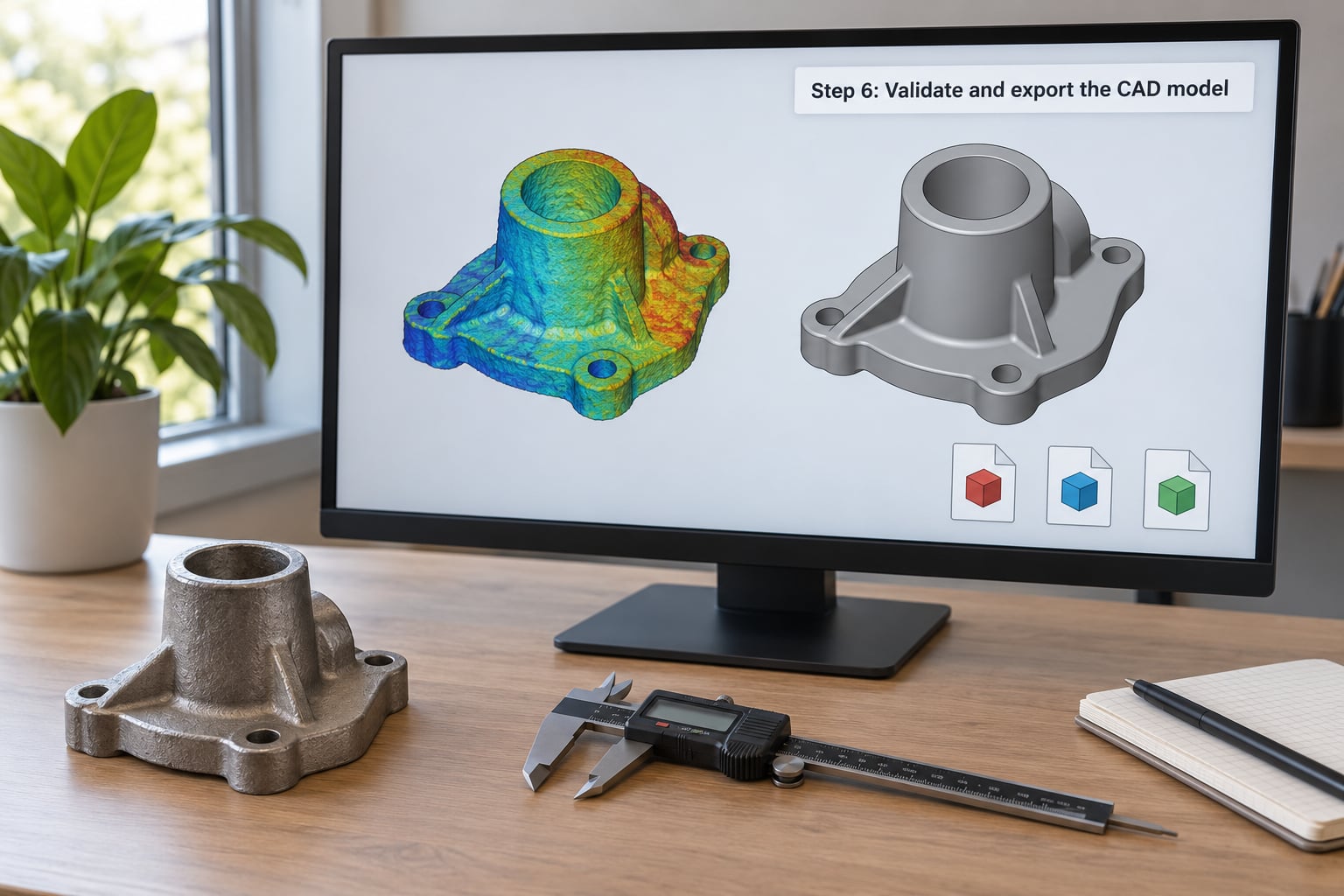
Validation is where the workflow either proves itself or quietly fails. Start with a deviation comparison, which most suites will do directly: overlay the CAD model on the scan and read the colour map. A healthy result is a thin band of colour near zero with a smooth gradient; scattered red and blue means the model and the scan disagree about shape.
Then check the things a deviation map cannot see. Is the scale right? Measure a feature you know and compare. Are the datums where you intended? Are mating faces parallel and bolt patterns centred where the assembly expects them? If the part bolts to something, fit it to that something, because a 0.3 mm positional error is invisible on screen and obvious in assembly.
Use the right instrument for the dimension. A digital caliper handles outside and inside dimensions in the 0.1 mm range on a warm bench. A micrometer is the reference for shaft and thickness. A bore gauge checks hole size properly. A CMM or a laser tracker handles anything with a real tolerance stack, and that is where professional RE work gets verified.
Export in the format the next tool expects. STEP (AP214 or AP242) is the default for handing a solid to another CAD system, and IGES still has a place for pure surfaces. DXF carries 2D sections and profiles. STL and 3MF go to the slicer. OBJ keeps vertex colour and texture, which is for rendering, not manufacturing.
The checkpoint: open the exported file fresh, measure a handful of features, and confirm the solid is closed with no gaps. Ten minutes here replaces a scrapped part.
Common mistakes
Treating the scan as an exact surface. The scan is a record of one real part, with wear, burrs, an old scratch and possibly a dent. Model the design intent where you can infer it, and keep the as-found geometry where the wear is the point, like a worn bearing seat you are matching.
Losing the scale. Import settings that assume a unit you do not have will silently change every dimension. Confirm scale against a measured feature before any other work.
Leaving holes unfilled. Unfilled drop-out blocks solid creation, and unhealed edges fail to stitch. Fill them, then check the fill did not bulge the surface.
Producing non-manifold geometry. Overlapping surfaces, zero-thickness walls and duplicate faces all make a solid that some CAM systems accept and others reject. Run the geometry check before export rather than after.
Over-smoothing details. Aggressive smoothing and heavy decimation erase fillets, chamfers and hole edges. Work in stages and compare against the original after each one.
Confusing a mesh with a CAD model. If you cannot change a dimension in the file, it is not a CAD model yet. Print it, view it, or machine it as a mesh only where that is genuinely enough.
Aligning badly and blaming the scanner. A 0.2 mm error on a part scanned in three passes is usually registration, not resolution. Re-run the best-fit and re-check the datums before you blame the hardware.
Scanning before deciding the deliverable. This one wastes the most time. Know whether the output is a print, a machined part or a drawing before the first pass, because the capture strategy, the density and the cleanup all follow from it.
Three habits keep projects out of trouble. Keep the raw scan untouched and work on a copy. Save versions at each stage so you can see which operation caused a problem. And take section profiles early, because they are the single most useful thing for hand-rebuilding a part.
Frequently Asked Questions
What is the best software for converting 3D scans to CAD models?
For most prismatic parts, Geomagic Design X and PolyWorks Modeler detect planes, cylinders and fillets automatically and rebuild them as editable features. Xtract3D and EXModel do the same job for less money. Free and open source is genuinely workable: CloudCompare and MeshLab clean the mesh, then FreeCAD rebuilds the solid with sketches and constraints. Fusion 360 is free for personal use and handles mesh reference geometry well.
Can I convert an STL file directly into a STEP file?
Not meaningfully. Any tool will wrap mesh triangles into a STEP shell, but you still end up with a faceted body that cannot be dimensioned, edited or machined. The file changes extension, not capability. To get a real solid you have to fit geometry to the scan and rebuild features, which is the reverse engineering step described above.
How long does it take to convert a 3D scan to a CAD model?
A simple machined bracket with a handful of holes and fillets usually takes one to two hours once the scan is clean. A complex assembly or a free-form mould insert can take days, because the fitting is iterative and every surface has to be checked. Add an hour or two for validation if the part has real tolerances, and expect longer the first time you do it in a new package.
What is the best CAD file format for 3D printing?
STL remains the safest default because every slicer reads it. 3MF carries colour, material and units, so it is better when you need multi-material or multi-colour output. Neither format holds dimensions or features, so print from the mesh directly if that is all you need, and keep the CAD model as the master for any later machining or revision.
Do I need CAD software if I already have a 3D scanner?
Only if you need more than a visual copy. A cleaned mesh is enough to 3D print a replacement, to check fit visually, or to archive a broken part. CAD software becomes necessary the moment you want to machine the part, revise the design, issue a toleranced drawing, or hand the job to a supplier who works from a model rather than a photograph.
Can ChatGPT or AI make a CAD model from a 3D scan?
Not a reliable one you can measure and machine. Text models can write scripts that generate parametric geometry, and auto-surfacing tools now use machine learning to fit surfaces faster than manual patching. Neither reads a point cloud and hands back a dimensioned, feature-based solid with verified accuracy. Use AI to speed up fitting, then check every dimension yourself.
Conclusion
Turning a 3D scan into a CAD model is real reverse engineering, and the workflow rewards discipline more than clever software. If you only take four things from this guide, take these: confirm the scan’s scale before you edit anything, clean the mesh gently so sharp edges survive, decide early whether you need a visual mesh or a parametric solid, and validate the finished model against the scan and a real instrument before you machine or print anything.
Start with the cheap end. CloudCompare and MeshLab for cleanup, FreeCAD for the rebuild, and a digital caliper for checking. Move to a professional package only when the auto-surface and feature detection genuinely pay for themselves on your parts, not before.