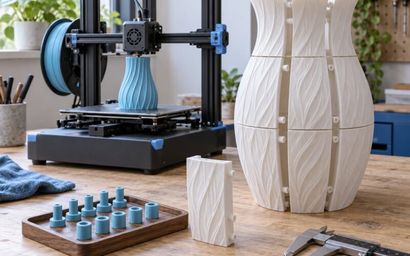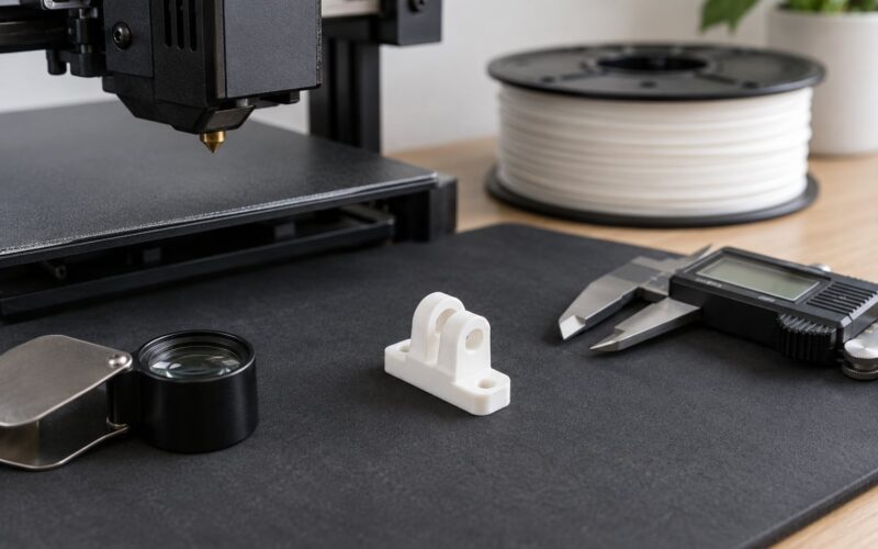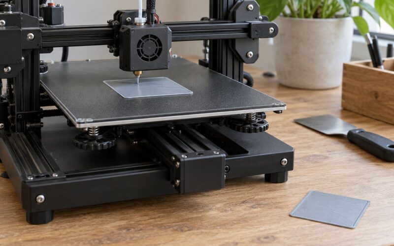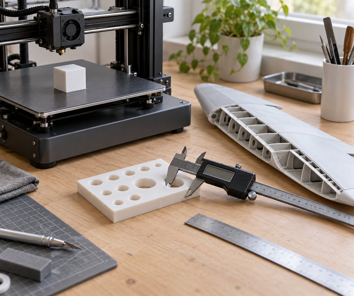
To print scale model parts accurately you control four separate things: the scale factor in your slicer, how much material your printer actually lays down, how much the material shrinks as it cools, and whether you verified the result before running a full kit. Get those right and a printed part mates with the rest of the model and reads correctly against the real thing it represents.
Getting them wrong is quiet. A part can look perfect and still be 1.5 percent oversize, which is 3mm of visible error on a 200mm wingspan and a peg that will not seat in its hole. Scale models are multi-part assemblies, so that error lands on every joint at once.
This guide walks through the whole chain, from deciding what size the part should be to measuring the finished piece with calipers. Most of it takes an evening. Updated for October 2026.
Table of Contents
- What You Need
- Step-by-Step: How to Print Scale Model Parts Accurately
- 1. Set the scale and write down your tolerances
- 2. Check and repair the 3D file
- 3. Choose the process that holds dimensions
- 4. Calibrate the printer with a test coupon
- 5. Set orientation, supports, and slicing
- 6. Print a scale test part
- 7. Measure and correct the errors that ruin scale accuracy
- 8. Print, remove, and finish the final parts
- Common Mistakes That Ruin Scale Accuracy
- Frequently Asked Questions
- Is FDM or resin more accurate for scale model parts?
- Why do my 3D printed parts come out slightly too small?
- How do I stop holes printing too small?
- What layer height should I use for small model details?
- How do I calibrate my 3D printer for accurate size?
- Should I print scale models at 100 percent?
- Conclusion
What You Need
Accuracy work needs less than people expect. The expensive part is usually the printer you already own, and the tool that actually makes the biggest difference is a pair of digital calipers costing less than a dinner.
- A source model. An STL or 3MF file, either from a model library, scanned from a real kit part, or modelled yourself in something like Fusion 360, SketchUp or Meshmixer.
- A scale reference. Real dimensions from a physical kit, official drawings, or measurements taken from the full-size original. This is what turns “looks right” into a number.
- CAD or mesh editing software to repair geometry, move parts to the plate, and confirm dimensions before slicing. Meshmixer or any CAD package works.
- A slicer such as PrusaSlicer, OrcaSlicer, Cura or Bambu Studio. All four can scale by exact millimetre and all four can compensate for hole size separately.
- A calibrated printer. Bed level, Z offset, flow and temperature verified, and a fresh nozzle if the old one has been running for months.
- Suitable filament or resin. Rigid PLA or PETG for FDM, a low-shrinkage casting resin for resin printing. Flexible TPU is a poor choice for anything that has to hold a dimension.
- Digital calipers with at least 0.01mm resolution. A cheap digital pair is genuinely good enough for this.
- Basic safety equipment for whichever process you use: eye protection and nitrile gloves plus a wash station for handling resin, and ventilation for ABS and ASA.
One thing worth sorting out early: FDM and resin are different workflows. FDM gives you a usable part quickly with almost no setup, and a calibrated machine lands roughly within plus or minus 0.5 percent. Resin gets you closer to plus or minus 0.2 percent with far more detail, but it adds washing, curing, supports and a chemical handling step. If your parts are 28mm wargaming minis you will want resin for the detail. If they are a 1:200 airframe that has to fit an existing kit, FDM with a good calibration routine is usually the more forgiving path.
Step-by-Step: How to Print Scale Model Parts Accurately
1. Set the scale and write down your tolerances
Decide the intended size before you touch any software, and express it in millimetres rather than percent. A 1:35 F-4 fuselage is not a percentage problem, it is a length problem, and entering the real length is the only way to avoid rounding.
Two approaches work. Either take one dimension from a real reference and scale the model to match it, or work from the scale ratio itself. Scale ratios are straightforward: 1:35 means the model is 1/35th the size of the original, so a 17.5m wingspan becomes 500mm. HO scale is roughly 1:87, N scale roughly 1:160, and 1:72 covers a lot of wargaming and aircraft kits.
For a miniature, 28mm is measured heel to top of head including the base, while 32mm is measured foot to top of head. Pick one and stay with it, because mixing the two produces a figure that looks wrong next to everything else on the table even when it is technically correct.
Then set a tolerance. For visible scale parts, plus or minus 0.2mm on a 100mm dimension is a reasonable target. For press-fit joints, budget 0.1 to 0.2mm of clearance per side. Write both numbers on paper before printing, because you will need them in step 7 and you will not remember them at midnight after a failed fit.
Success check: a sheet of paper with target dimensions in millimetres, one line per critical feature, and a chosen clearance for each joint.
2. Check and repair the 3D file
Most scale accuracy problems that get blamed on the printer are actually file problems. STL conversion is lossy, and a model that came through three different programs often has thin walls, flipped normals or geometry the slicer silently repairs in a way that shifts a dimension.
Load the file and run a mesh check first. You want a manifold mesh, meaning watertight: no holes, no self-intersections, no duplicate surfaces. Meshmixer has a direct analysis command, and the slicers all report repairs on import.
Then check the features that matter. Thin details below roughly twice your nozzle diameter will not survive printing and will get rounded off, which changes whatever they connect to. A 0.1mm antenna on a 0.4mm nozzle is not a detail, it is a memory of one. Either thicken it in CAD or accept the loss and compensate the part that receives it.
Orient the model for printing at this stage rather than fighting with supports later. Rotate it so the largest flat, visible surface faces down, since the bottom of the print is the one with the worst finish. Turn it upside down for miniatures, which puts detail on top and hides the base. If a part is longer than your build volume in both axes, laying it diagonally on the plate buys you real extra length, a trick that comes up constantly on scale builders forums for long wings or fuselages.
Finally, measure the model in your slicer with the measurement tool and compare against your target. If the cockpit opening is supposed to be 4.0mm and it reads 4.0mm in the slicer, then any error that shows up in the print came from the printer, the material or the process. That separation is the whole point of doing it now.
Success check: mesh reports manifold, no self-intersections, no repair prompt on import, and the critical dimensions read the intended values in the slicer.
3. Choose the process that holds dimensions
FDM extrudes molten plastic through a moving nozzle. Resin cures liquid photopolymer layer by layer with a light source. That difference shows up directly in the numbers, and it is worth knowing roughly what each process holds before you commit.
Published figures put FDM at around plus or minus 0.5 percent dimensional error, resin and SLA at around plus or minus 0.2 percent, and powder bed processes near plus or minus 0.3 percent. Real numbers on any specific machine will be better after calibration and worse before it. A budget printer that has never been calibrated can easily sit 1.5 percent off in both directions, and that shows up as a nominal 20mm cube measuring 20.3mm with nothing else looking obviously wrong.
Detail is the other dividing line. A 0.2mm nozzle at a 0.1mm layer height resolves features a 0.4mm nozzle never will, and a resin print at 0.02mm per layer is in a different category again. You can approach resin-like surface quality on FDM with a small nozzle and careful tuning, at the cost of long print times and real risk of clogging.
Shrinkage behaves differently too. PLA contracts as the part cools, ABS and ASA contract more and continue moving as they cool over hours, and resin shrinks during cure as the polymer crosslinks. Each of these has a different correction, covered in step 5.
Post-processing is where dimensionally careful people often lose their tolerances without noticing. Heavy sanding and filler remove material and shrink the part. Light wet sanding with 400 to 800 grit barely moves a dimension. Know which one you are doing.
Success check: process chosen for the tolerance you need rather than the surface finish you want, and the error budget judged against the actual part size.
4. Calibrate the printer with a test coupon
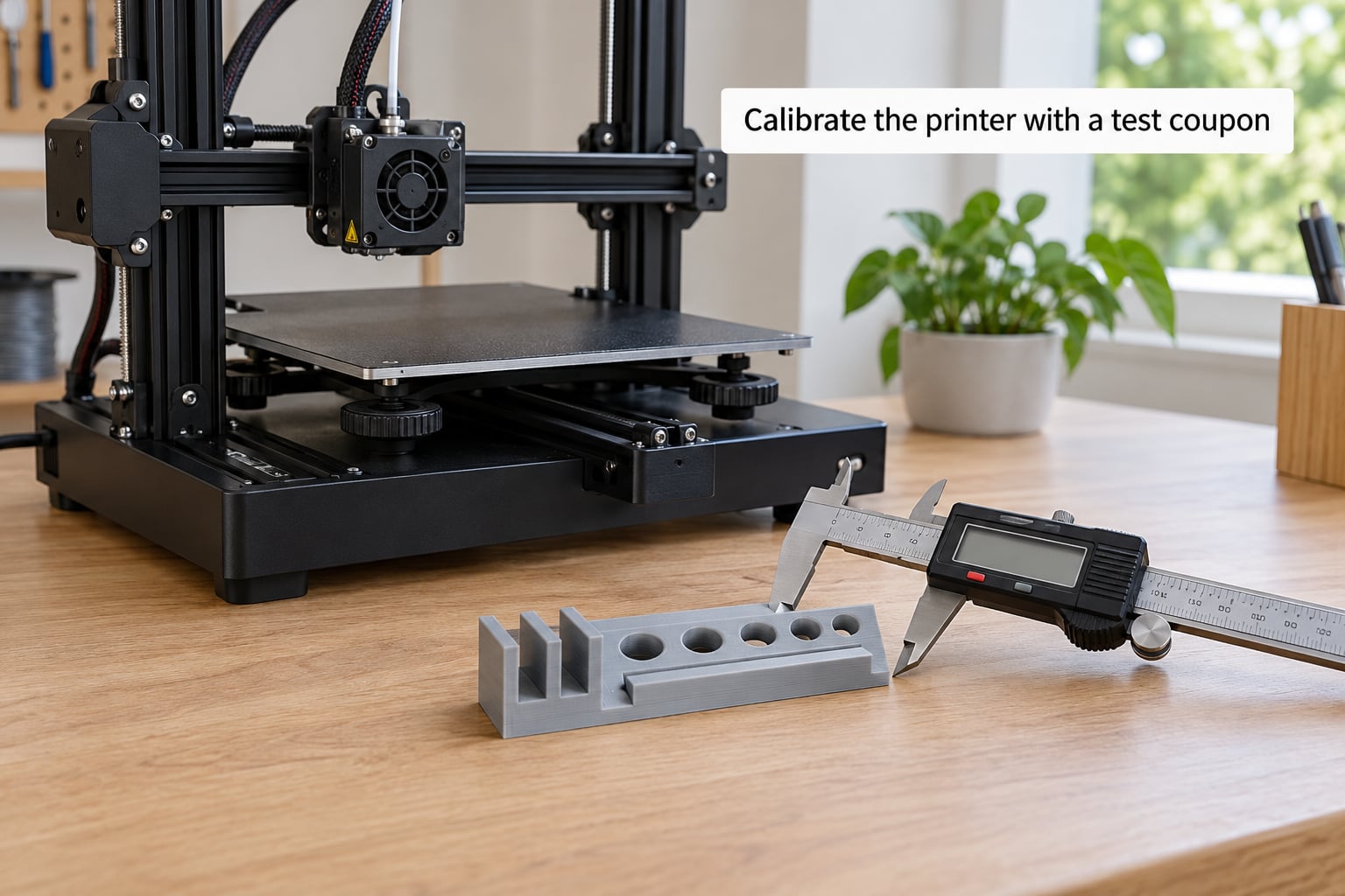
This is where accuracy is actually won or lost. A printer that has drifted will produce consistent wrong answers forever, and no amount of careful measuring at the end will fix it.
- Level the bed with a paper test, then set the Z offset so the nozzle sits at the right height for a first layer that sticks without being crushed flat.
- Check temperature on the hotend and bed with a separate thermometer rather than trusting the setpoint. A block or cube printed too cold shows ridges on the sides and poor layer adhesion, and neither helps a dimension hold.
- Run a flow rate test and set the flow or extrusion multiplier to match. This corrects how much plastic actually lands per millimetre of line.
- Print a calibration cube at 20mm and measure the X, Y and Z faces with calipers, plus the width of a hole and the diameter of a pin.
- Correct XY size if the cube is off, and set hole horizontal expansion to bring the hole back to nominal.
This is where a lot of arguments start. The usual advice from experienced scale builders is not to calibrate XY from a bare cube alone, because a cube tests one wall thickness in one orientation and generalises badly to a thin panel or a small feature. Use a flow test for extrusion width and a dedicated hole or pin test for compensation, then treat the cube as a sanity check.
Measure at the same three places on each face, away from the first layer and away from seams. Record the numbers and save them in a slicer settings file. A settings file per material and per scale is the difference between a repeatable kit build and a week of guessing.
Success check: calibration cube within 0.1mm of nominal on X, Y and Z, hole and pin dimensions measurable, and all values written into a named settings profile.
5. Set orientation, supports, and slicing
Most slicer mistakes that hurt accuracy are made here rather than at the printer. Scale the model by exact millimetre dimension instead of by percentage, and use the slicer’s scale lock so the value does not drift when you move something else.
In PrusaSlicer and OrcaSlicer, open the Move or Scale tool and enter the real target size in millimetres rather than typing a percentage, and enable the option that locks uniform scaling. In Cura, use the uniform scale field with its scale factor link enabled, or use the horizontal and vertical size fields to enter an absolute measurement. In Bambu Studio the same logic applies under the model transform panel. Entering an absolute measurement is the fix that matters most, because percentage scaling compounds every time you rescale.
Then set hole compensation. The setting is called hole horizontal expansion in Cura, XY compensation or hole compensation in PrusaSlicer and OrcaSlicer. What it does is push internal hole edges outward without touching the outer model dimensions, which matters when the whole problem is that your pegs do not fit. Vertical expansion does the same job in the other axis for holes that run along Z, and you will need it for anything with a vertical bore.
For the layer settings, layer height is the single biggest lever on visible detail. A sensible starting profile is a 0.4mm nozzle, 0.1mm layer height, three shells at about 1.2mm of wall, 210C PLA, 40mm/s and 50 percent grid infill, which runs roughly 2.5 hours for one acceptable 28mm figure. That profile is a reasonable starting point, and for accuracy you can go finer: 0.06 or 0.08mm layer height on a well-tuned machine.
Speed affects dimensions more than beginners expect. Slow the outer wall, which in most slicers is the first or first two perimeters, to roughly half your normal print speed. Finer layers, more perimeters and lower fan speed all help the outer wall hold its width. Infill density barely matters for a rigid part since the walls do the work, so leave it low and save hours.
Supports are a trade. Too few and the part distorts as it cools; too many and the support interface leaves a witness mark across a surface that has to fit. Never place a support on a mating surface if you can avoid it. For resin, orient the part so the parting line falls on a face you can sand, then choose supports that touch the least critical geometry.
Success check: the preview shows no support interface on any fit surface, and the hole width in the preview matches your intended diameter after compensation.
6. Print a scale test part
Do not slice the whole kit yet. Pick one representative part and print it with the same material, the same profile and the same orientation you plan to use for the rest.
Choose a part that is diagnostic rather than convenient. A wing panel, a hull section or a base plate with a hole in it tells you about flatness, wall thickness and hole compensation all at once. A tiny decorative greeble tells you almost nothing. Ideally the part should be near the size of the real thing and include at least one hole, one shaft and one flat mating surface.
Run the print with no other jobs on the machine and keep the door closed if the filament is PLA or ABS. Ambient temperature swings of several degrees during a long print will show up as a dimensional difference between the first layers and the last.
Let the part cool fully before you touch it. PLA parts come off the plate hot and continue contracting for a while, and a measurement taken straight off the bed is not the size the part will be tomorrow.
Success check: the part removes from the plate without flexing, and it reaches a stable, measurable state within about an hour of coming off.
7. Measure and correct the errors that ruin scale accuracy
Measure with calipers in the same spot every time. Check external dimensions on X, Y and Z, then a hole diameter, then a pin or shaft diameter, and note the position of each measurement so you are comparing like with like.
Work out the percentage error with a simple calculation: (measured minus target) divided by target, multiplied by 100. A hole that should be 4.00mm and measures 3.84mm is 4 percent undersized, which is a lot. A cube that should be 100mm and measures 100.3mm is 0.3 percent over, which most people can live with visually.
Now decide which knob fixes it, and this is the distinction that separates a real fix from a fudge. Error that changes with wall thickness, hole size and perimeter count is slicer or flow related, so adjust flow, extrusion multiplier or hole compensation. Error that is the same percentage in every direction and across the whole part is material shrinkage, so apply a uniform scale factor. Error that only shows up in Z on the bottom edge is elephant foot, so raise the first layer height or set a Z offset adjustment rather than scaling the model.
For a consistent percentage error, divide the target by the measured value to get a correction factor. If a 100mm feature reads 99.4mm, multiply the slicer scale by 100 divided by 99.4, which is about 1.006. Apply it once, never twice.
Then reprint the same test part with the correction applied. One reprint tells you whether your theory was right, and it is much cheaper than discovering the error after 30 parts are in the queue.
Success check: the reprinted test part lands within 0.1mm of target, or inside the clearance you budgeted for that joint.
8. Print, remove, and finish the final parts
Print the full set with the corrected profile and the same material lot if you can. Filament from a different batch can sit a fraction of a percent off, and across a multi-part kit that difference shows up as joints that fit at the front and not at the back.
Remove parts from the plate the way the material intends. Peel PLA slowly at room temperature or use the spatula under a scraper at the edge. Bend the plate away from a resin part rather than levering against the part itself, since resin prints are brittle and the base usually snaps cleanly if you flex the plate. Avoid dragging a metal tool across the build surface, which scars it and affects the next print’s first layer.
Clean resin parts fully in isopropyl alcohol and cure them on the back of a sunny window or under a curing lamp until they are not tacky and no longer cool to the touch. Under-cured resin keeps shrinking slightly for days and keeps growing more brittle.
Clean up supports with flush cutters and a craft knife at the joint rather than sanding the part down to the support mark. If you do need to sand, go no coarser than 200 grit and follow with 400, and re-measure afterwards because you have changed the dimension.
Then do a dry fit with nothing glued. Every joint should assemble with light pressure or a small amount of friction. A part that needs a mallet to seat is a part you should reprint, and one that falls off has clearance you can claw back with compensation rather than filler.
Finally, write down what worked: filament, temperatures, layer height, wall count, scale factor, hole compensation, support type. The next kit you print on the same machine with the same material will start from those numbers instead of from nothing.
Success check: the whole batch is inside tolerance on the caliper, joints fit dry, and the settings that produced it are saved as a named profile.
Common Mistakes That Ruin Scale Accuracy
- Scaling the model twice. You set 50 percent in CAD, then type 200 percent into the slicer to make up for what the CAD scale did, and the part is 10mm off with no obvious cause. Scale in one place only. Pick the slicer, use absolute millimetres, and leave the source file alone.
- Scaling by percentage instead of by real dimension. Percentages compound silently through every resize. Enter the actual measurement you want, every time.
- Calibrating XY from a bare cube. A cube tests one geometry. Use a flow test and a hole or pin test, then confirm with the cube. The argument on this recurs constantly, and the cube-only method is the most common cause of features that pass on paper and fail in the hand.
- Ignoring elephant foot. The first few layers bulge outward, and a part measured at the base is bigger than the same part measured at the top. Measure in the middle of the part, and raise first layer height if the bulge ruins a fit.
- Printing holes at nominal size and wondering why pegs do not fit. Holes come out undersized because the extrusion path is pushed outward by the slicer and by the material. Use hole horizontal expansion to push them back, and the outer dimensions stay where you want them.
- Supporting everything. Heavy supports add stress, leave marks and cost hours. Support only what needs it, and keep interfaces off mating surfaces.
- Changing filament between prints in the same kit. Different rolls and different materials carry different shrink. Print a kit from one spool, and dry wet filament first because moisture changes both flow and layer bonding.
- Measuring a warm part. Most materials are still contracting when they come off the plate. Wait, then measure twice, in the same place.
A few habits cover most of the rest. Print orientation is free accuracy, so put the best surface up and the worst surface on the plate. Slow outer walls cost nothing and hold size better than a faster print. Use a fresh nozzle, because a partially blocked one produces inconsistent extrusion width. And keep a small parts bin for failed prints, because a rejected test coupon is a free source of calibration data for the next correction.
Frequently Asked Questions
Is FDM or resin more accurate for scale model parts?
Resin is more accurate. Published figures put resin and SLA printing near plus or minus 0.2 percent dimensional error against roughly plus or minus 0.5 percent for FDM, and resin resolves far finer features at thin layer heights. FDM is easier, faster and safer to handle. For 28mm wargaming minis, resin wins on detail. For large panels and kits that must fit existing parts, a well-calibrated FDM machine is often simpler.
Why do my 3D printed parts come out slightly too small?
Most often it is flow: the printer extrudes slightly less than the slicer asked for, so every wall comes out narrow. Run a flow rate test and set the extrusion multiplier accordingly. Second most common is material shrinkage as PLA or ABS cools and contracts. Test with a 20mm calibration cube, calculate the percentage error, and divide target by measured to get a correction factor. Apply it once.
How do I stop holes printing too small?
Use hole compensation rather than scaling the model. Hole horizontal expansion in Cura and XY or hole compensation in PrusaSlicer and OrcaSlicer push internal hole edges outward while leaving the outer model dimensions untouched, so your overall scale stays correct. Measure a printed hole with calipers, work out the percentage it is undersized, and enter that value. Check vertical expansion too for any bore running along Z.
What layer height should I use for small model details?
For a 28mm figure on a 0.4mm nozzle, 0.1mm is a solid baseline and 0.06 to 0.08mm gives noticeably crisper detail if the machine is well tuned. A 0.2mm nozzle handles 0.06 to 0.1mm layers without risking a clog. Keep layer height at or below 75 percent of nozzle diameter, and remember that anything thinner than roughly twice the nozzle diameter will be rounded off regardless.
How do I calibrate my 3D printer for accurate size?
Level the bed, set Z offset, verify hotend temperature with a separate thermometer, then run a flow rate test to set extrusion multiplier. Print a 20mm calibration cube and measure all three axes plus a hole and a pin. Correct XY size from the result and set hole compensation for the bore. Avoid calibrating XY from a bare cube alone, since one geometry generalises badly to thin panels and small features.
Should I print scale models at 100 percent?
Not as a number you type and trust. Print at whatever the slicer scale happens to be and set the real target dimension instead, using an absolute millimetre value rather than a percentage. That way the part matches its reference no matter what the source file scale was. Write the intended dimensions down first, then scale to meet them and verify with a first-article test print.
Conclusion
Accurate scale printing comes down to four things, and none of them is the printer itself. Lock the scale in one place using a real millimetre target. Calibrate flow so the walls come out the width the slicer intended. Compensate for hole size and for the shrinkage of the material you actually chose. Then measure a first-article part with calipers before committing to the full set.
Start with the first two steps. Decide the scale and the target dimensions, then check the source geometry is clean and actually measures what you think it does. Print one calibration part from a real feature of the model, measure it, and correct from there. Everything after that is just applying a saved profile to the rest of the parts.