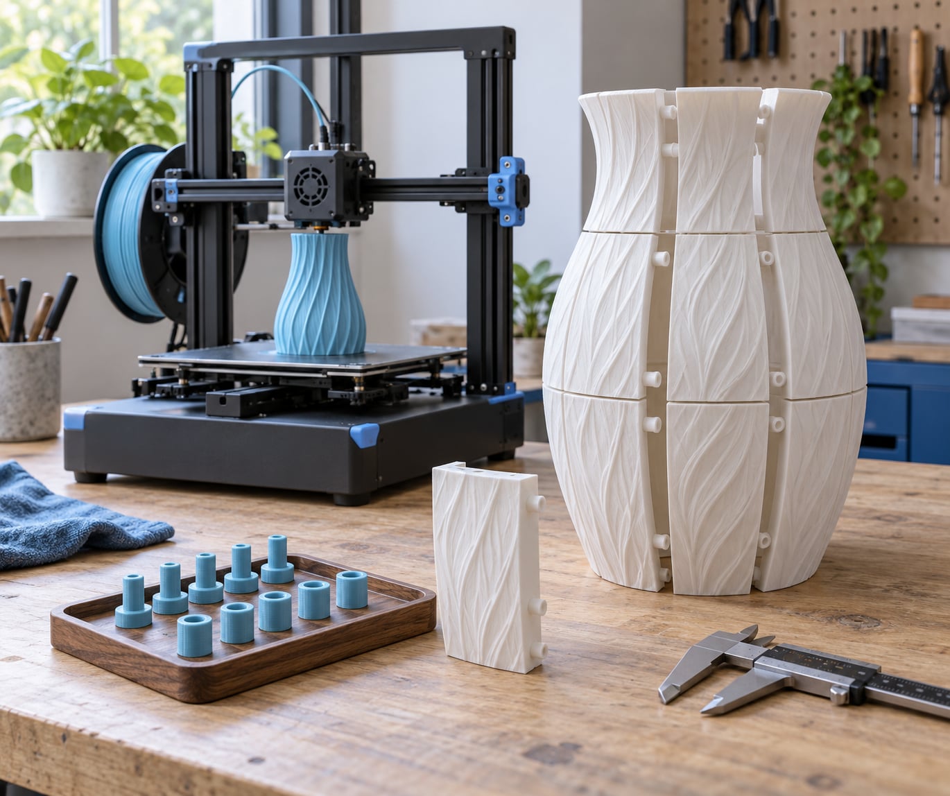
You cannot print a large object on a small 3D printer in one piece. The only way to get the full size is to scale the model down, split it into sections that each fit your build plate, print those sections, and join them back together with pins, dovetails, screws or adhesive. This guide is about 3D printers, since the phrase also turns up inkjet and paper results.
The work takes planning more than printing skill. A twelve-section build might run forty hours across four days, and one badly placed seam can undo all of it. Measure first, cut deliberately, fit-test a single joint, and only then print the batch.
Everything below is written for desktop FDM machines in the 180 to 256 mm build volume class, and it applies to resin printers too, with the pour-volume caveat further down. Updated for 2026.
Table of Contents
- What You Need
- Step-by-Step: How to Print Large Objects on a Small Printer
- 1. Scale the Model to Fit the Build Plate
- 2. Split the Model into Tiled Sections
- 3. Print Interlocking or Modular Parts
- 4. Use a Temporary Bonding Method When Tiling Is Not Possible
- 5. Strengthen the Print for the Largest Result
- Common Mistakes
- Frequently Asked Questions
- Can you print an object larger than your 3D printer’s build plate?
- What is the best way to split a large 3D model for printing?
- How do you line up tiled 3D print sections accurately?
- Can you join 3D-printed parts without visible seams?
- Should you scale a large model down or print it in separate sections?
- How do you make a small printed model strong enough for a large project?
- Conclusion
What You Need
A printer with a known build volume, and a slicer that can cut a model. That is the core kit. Everything past that depends on the size of the object and how much shaping work you are willing to do in CAD.
- The printer and its real usable volume. Most home machines print 180x180x180 mm up to 256x256x256 mm. Your usable area is always smaller than that, because the skirt, brim, excluded zones near the clamps and the bed edge all take space.
- A slicer. PrusaSlicer, OrcaSlicer, Bambu Studio and Cura all have a cut or split tool that slices a mesh with a plane and offsets the pieces slightly so they are not coincident.
- A CAD or mesh editor if your cut is not a straight plane: Fusion 360, SolidWorks, FreeCAD or Blender. FreeCAD and Blender are free and both can divide a body with a boolean.
- Material in enough quantity for every section plus scrap. Multi-section builds fail more often than small prints, so budget at least one spare of the hardest section.
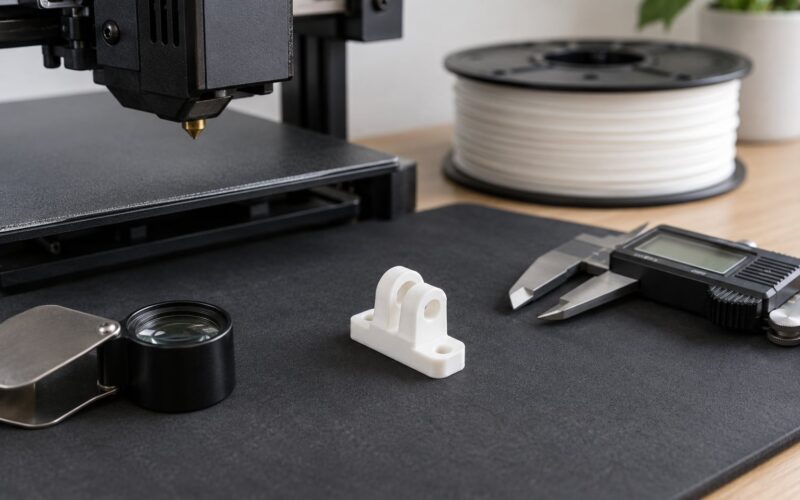
- Calipers and a flat plate or scrap of glass for the fit test, plus 80 to 120 grit sandpaper, filler and a soldering iron for reinforcing joins.
- Fasteners or hardware if you want the assembly to come apart: M3 or M4 screws and nuts, heat-set threaded inserts, dowel pins, or small neodymium magnets.
Two compatibility checks are worth doing before anything else. Print a single wall line or a small pin test at the same material and temperature you plan to use, because a joint designed on a well-tuned printer will not transfer to one that is running cold. And confirm your slicer version still writes connector geometry into the project file, since exporting to STL can silently drop socket and hole details that only exist as negative volume in the slicer scene.
Step-by-Step: How to Print Large Objects on a Small Printer
There are four decision paths, and picking the wrong one wastes the most time. Scale the model if the object is decorative and small reductions are acceptable. Tile it if the shape is roughly regular and you can hide a seam. Design it as modular interlocking pieces if you are comfortable in CAD. Use a temporary bond only when you have no choice, such as a one-off mould or a shape with no natural split line.
Before any of that, measure the model. Load it into your slicer, look at the bounding box on all three axes, and compare it against your usable build volume with room to spare. Cutting exactly to the advertised machine limit is the most common early mistake, because it leaves nothing for the brim, the skirt or the excluded zone at the bed edge. Leave ten to fifteen millimetres of margin on each edge of the bed, and more if the part is tall and needs bracing.
1. Scale the Model to Fit the Build Plate
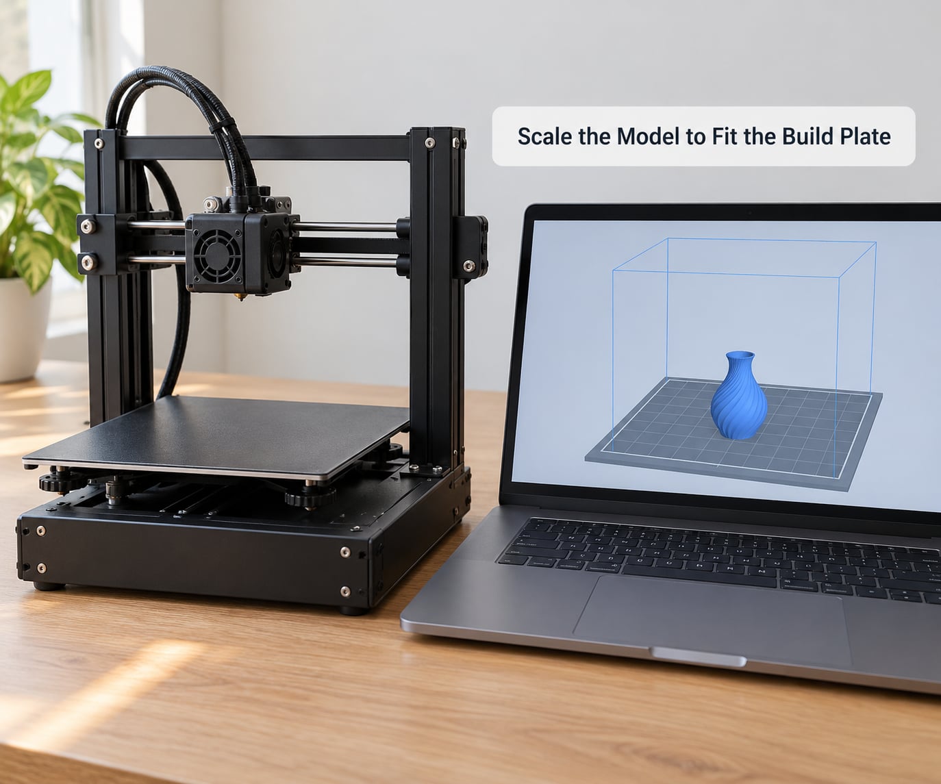
Scaling is the simplest path and the one most people overlook. In your slicer, select the model and use the scale function, then type exact dimensions rather than a percentage so the result is predictable. Scaling to 90 percent on a 250 mm object drops it to 225 mm, which often clears the limit on its own.
Know what scaling costs you. Walls get proportionally thinner, fine detail closes up, and thin features like a sword blade or a chain link can disappear entirely in the slicer preview. Print strength falls as a square of the scale factor, so a 70 percent scale is roughly half as stiff in bending. If the object is a display piece, that is an acceptable trade. If it carries load, scaling is the wrong choice.
Confirm the result before printing: check the scaled dimensions in the model properties, rotate to the intended orientation, and confirm the first-layer footprint sits inside the plate with clearance on every side. A tall part that fits on the plate but overhangs the build height still will not print.
2. Split the Model into Tiled Sections
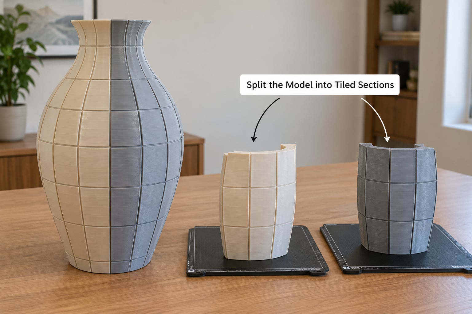
Tiling means cutting the model into pieces with a shared, flat cut plane. In a slicer, add a cube or cylinder over the model, raise it above the surface to be cut, and use the cut tool. The pieces separate, and a small positive offset keeps their faces from being exactly coplanar, which stops the slicer merging them back into one solid.
For a cut that is not a single flat plane, open the mesh in a CAD tool instead. In Fusion 360, use Split Body with a plane or a body as the tool. In Blender, add a cube, apply a boolean difference, then separate by loose parts. In FreeCAD, use the Part boolean and the same intersection-box trick. Online STL splitters exist, but they do the same plane cut with fewer controls and no way to add alignment features.
Seam placement matters more than the cut itself. Put the joint where it is least visible and least loaded: around a waistline, under a brim, along a panel line, or on a face that points at the floor. Avoid cutting across the direction of primary load, because a glued butt joint across a bending axis is the weakest point in the whole assembly. Cut across a flat panel rather than around a curve if you can, since flat mating faces sand and glue far better than curved ones.
Give every cut edge matching alignment features on both halves. Circular pins on one side and matching sockets on the other, or a rectangular tongue and groove, register the pieces far better than two flat faces pushed together. Keep the features at least 3 mm across so they print reliably, and put two or three around the perimeter rather than one in the middle. Leave the mating faces at their exact printed size for the first test, then adjust from the measurements you take.
Export each section as its own file and keep the slicer project file too. The 3MF project holds your settings, custom sockets and part placement. Label every piece with a short code and emboss the same code into the model surface so you can identify it after a week of prints.
3. Print Interlocking or Modular Parts
Modular design is the cleanest answer when you control the model. Instead of cutting a solid shape and repairing it later, build the object from the start as separate pieces with a planned joint. Tabs and sockets work for printed-in-place style assembly, dovetails lock without adhesive, and a printed hinge gives you a part that folds for transport and unfolds for display.
A dovetail is the strongest printed joint because it mechanically prevents the pieces sliding apart, and it needs no glue or hardware. Chamfer the entry end by about one millimetre so the two halves self-centre during assembly, and round the internal corners slightly so a nozzle can reach them without leaving a hole. Dovetails print with no support as long as the flare angle is gentle and the dovetail sits at or above the seam between layers rather than half a layer above it.
Test before you commit. Print one pin and its socket, or one pair of dovetails, at the real material and real orientation, then check the fit with calipers. There is no universal clearance value for printed joints. A number that works on a well-tuned machine with 0.4 mm line width will be too tight on one running 0.1 mm under-extruded, and the same geometry in PETG at a lower temperature shrinks differently than PLA. Measure, adjust, reprint the coupon, then commit.
Register your pieces in pairs before building up. Print and dry fit every A part against its B part while the table is still clear, because a single misfit found early costs one small print instead of a full batch.
4. Use a Temporary Bonding Method When Tiling Is Not Possible
Some shapes have no sensible cut line, or you want the join to be reversible. That is where bonding or fastening comes in, and each method has real limits.
Solvent welding fuses ABS and ASA parts chemically. Work outdoors or with strong extraction, never in a closed room, and wear a respirator rated for the vapour. Apply the solvent to both mating faces, press them together with clamps, and leave them undisturbed for the full cure. The result is as strong as the surrounding material and invisible at the seam, but the parts cannot be separated afterwards.
Heat welding uses a soldering iron with a fine tip to melt the mating faces together. It works on PLA, ABS and PETG, needs no ventilation, and gives you precise control over small seams. Keep the tip moving, work in short passes, and let the piece cool untouched. This is the technique people use to reinforce weak corners after a load test fails.
Adhesive fills gaps instead of creating a structural joint on its own. Roughen both faces with 80 to 120 grit paper, wipe them clean, apply a thin even layer, clamp, and wait for the full cure the product specifies rather than a few hours. A gap filler or epoxy that is slightly thicker than the visible gap will survive the loads that thin cyanoacrylate alone cannot.
Mechanical fasteners suit anything that must come apart or carry real load: countersunk screws into printed bosses or nuts captured in pockets, heat-set threaded inserts pressed into reinforced holes, dowel pins locating the halves, and magnets where you want a clean look with no visible hardware. Tap threads directly into plastic only for small screws, and reinforce the boss with more perimeters so the thread has material behind it.
Whatever you use, load-test it before you rely on it. Print the joint at full scale, apply the intended load gradually, and keep the section that matters most until last in your build order.
5. Strengthen the Print for the Largest Result
Large parts fail differently from small ones. Big flat areas warp because the corners cool first and the centre is held flat by bed adhesion, so the plastic pulls itself out of plane. Tall thin parts wobble and separate along layer lines under load. Fixes cost print time, so apply them where the part needs them.
Bed adhesion first. Add a brim for large footprints and tall prints, four to eight layers, because it increases the contact area with the plate. Use a raft instead when the part is short, wide and flat. Clean the plate and re-level before a long build, because you will not be watching it.
Calibrate the first layer. Compensate for elephant foot, the slight bulge on the bottom edge that makes a mating face sit proud and stop the joint closing fully. Print a single wall around a test coupon, measure it, and adjust your flow or Z offset until the wall matches the width your design assumes.
Control the environment. ABS and ASA need an enclosure to control shrinkage; open-door printing makes large parts inconsistent. Keep doors closed and add a brim if the corners lift.
Raise wall thickness and infill for the loaded sections. More perimeters beat higher infill for bending strength, because they move the failure point away from the layer lines. Keep infill moderate and spend the extra time on walls.
Reduce print speed for large sections. Fast moves on a wide footprint shake the part, and cooling time matters more than flow at scale.
Orient each section so layer lines run along the load path rather than across it, and add supports only under genuine overhangs. A part buried in support material is hard to sand, hard to glue and full of voids.
Finally, estimate the whole batch before you start. Multiply filament and time by the section count, add 15 to 20 percent for failure and support waste, and check it against your spool and your week. Knowing the total turns a hopeful build into a plan.
There are cases where none of this is worth doing. If the object is larger than roughly 400 mm in any direction, a large-format printer or a print bureau will usually beat a dozen split sections on time, cost and surface quality. If the object is a mould or a one-off shape, a single vacuum-formed or routed shell beats glue-up entirely. And if the object is too tall but not too wide, cut it horizontally rather than vertically: a vertical seam splits the load path and leaves an obvious line, while a horizontal cut through a flat base keeps every section symmetrical and hides the join under the model.
Common Mistakes
Almost every failure traces back to one of these. Read the list before the print, not after it.
- Cutting to the exact machine limit. Fix: leave ten to fifteen millimetres per edge for the brim, skirt and exclusion zones. Re-measure the usable area, not the advertised volume.
- All-flat seams with nothing to register them. Fix: add two or three alignment pins or a tongue-and-groove feature to every joint. Two flat faces pushed together drift the moment you handle them.
- Copying a clearance value from someone else’s machine. Fix: print a coupon on your printer, at your material and settings, and measure. Adjust by the error you measured, not by a rule of thumb.
- Layer splitting in the finished part. Fix: more perimeters, slower speeds, and an enclosure for ABS and ASA. If the split lands exactly on your seam, your joint is taking a load it was never designed for; move the seam or use a mechanical joint.
- Glue-only seams on load-bearing parts. Fix: use dovetails, screws or inserts to carry the load, and let adhesive fill and seal rather than hold.
- Excessive supports. Fix: rotate the section to reduce overhangs, lower the support threshold angle, and set the support distance from the surface so the part is easier to clean off.
- Accidental scaling. Fix: check the model dimensions in the slicer before slicing. A section dragged out of position or scaled by a stray keystroke still slices, and you find out twenty hours later.
- Printing the whole batch before testing one joint. Fix: print the hardest, most critical section first, fit it, then run the rest.
- Unnumbered parts on a full table. Fix: emboss an identifier into each section and keep a printed cut plan beside the printer. Filenames alone stop being useful past about twenty pieces.
- Losing the project file. Fix: keep the 3MF alongside the STL, because socket and hole geometry can vanish on export.
Frequently Asked Questions
Can you print an object larger than your 3D printer’s build plate?
Not in one piece. To print at full size on a small printer you must segment the model into sections that each fit your usable build volume, print them separately, then join them with alignment pins, dovetails, screws, magnets or adhesive. Scaling the model down is the only single-piece option, at the cost of wall thickness and detail.
What is the best way to split a large 3D model for printing?
Use a straight plane cut through the model, usually with your slicer’s cut tool and a cube placed above the cut line. For curved or irregular shapes, use a CAD or mesh editor such as Fusion 360, FreeCAD or Blender, place a boolean body or plane and separate the result by loose parts. Leave bed clearance and give both halves matching alignment features.
How do you line up tiled 3D print sections accurately?
Build matching alignment features into both halves, such as circular pins and matching sockets or a tongue and groove, and place at least two around the perimeter. Chamfer the entry so the parts self-centre, keep features at 3 mm or larger, and print one test pair at your real material and orientation to calibrate the clearance before the full batch.
Can you join 3D-printed parts without visible seams?
Yes, with the right method. Solvent welding ABS or ASA gives a bond as strong as the parent material and no visible line, but needs ventilation and a respirator. Heat welding with a fine soldering iron tip is nearly as good on PLA and PETG. For the best result, design the split line along a panel edge or shadow gap and fill, sand, prime and paint.
Should you scale a large model down or print it in separate sections?
Scale it down for decorative objects where a smaller result is acceptable, but remember that wall thickness, detail and stiffness all fall with the scale factor. Print separate sections when the true size matters, when the part carries load, or when the details would close up. If the object is more than roughly 400 mm, compare the effort against a large-format printer or a print bureau first.
How do you make a small printed model strong enough for a large project?
Add perimeters rather than infill, since walls move the failure point away from the layer lines. Orient the section so layer lines run along the load path, slow the print speed on wide footprints, and use a brim or raft to stop warping. Put a mechanical joint, such as dovetails or screws, across the seam, then load-test it at full scale before you rely on it.
Conclusion
Start with the build volume, not the model. Measure the model’s true size on all three axes, compare it with the usable area of your plate after subtracting the brim and exclusion zones, then pick your path: scale it, tile it, design it modular, or bond it.
Before committing to the full build, print one test pair of the joint at your real material and orientation, measure the fit, and load-test it. That single coupon costs an hour and tells you more than any guide can.