First layer calibration is the process of setting the correct distance between your 3D printer’s nozzle and the print bed, usually stored as a Z-offset value, so the first layer squishes slightly and bonds to the build plate. You do it by leveling the bed, cleaning the plate, heating the printer to real print temperature, and adjusting the offset in small increments until the lines merge into one continuous sheet. It takes about 20 minutes end to end, including one test square.
The reason it matters is simple: everything printed above sits on top of that one layer. A first layer with gaps under-extrudes and the part lifts. A first layer that’s over-squished gives you an elephant foot and a wavy bottom edge. And an offset that’s off in one corner shows up as a part that’s flat everywhere except where it isn’t.
Below is the whole process, in the order that saves you the most time. The most common mistake happens at step one, and it isn’t a calibration mistake at all.
Table of Contents
- What You Need
- Step-by-Step: First Layer Calibration Step by Step
- 1. Prepare the Printer and Build Plate
- 2. Set Material and Printer Conditions
- 3. Inspect the Nozzle for Extrusion Problems
- 4. Run a Nozzle-to-Bed Clearance Test
- 5. Adjust Z-Offset or Paper Spacing
- 6. Calibrate Extrusion or First-Layer Flow
- 7. Print and Verify a Full Test Pattern
- Common Mistakes
- Calibration Tips for Reliable Results
- Frequently Asked Questions
- Do I need to calibrate the first layer every time I start a print?
- What Z-offset gives a good first layer?
- Should I use a paper test or the printer’s Z-offset calibration?
- Why does my first layer stick but later layers separate?
- Do I need separate first-layer settings for PLA and PETG?
- Why are the corners of my first layer worse than the straight lines?
- Conclusion
What You Need
You need very little, which is why this is a good first calibration to learn.
- The printer, with the build plate installed and located properly.
- A slicer — PrusaSlicer, OrcaSlicer, Cura or Lychee. PrusaSlicer has a first layer calibration tool built in; the others need a test model printed manually.
- Your normal filament. Calibrating on a different material than you print with wastes the work.
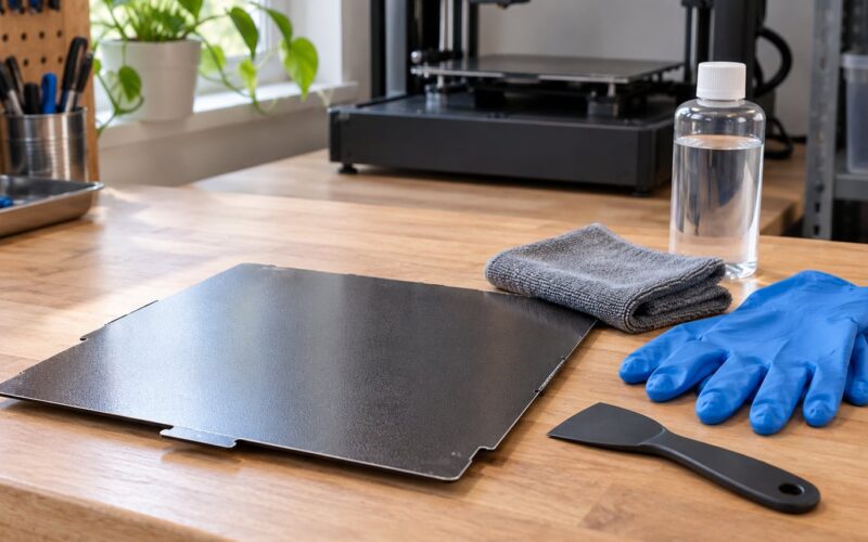
- Cleaning supplies: 90%+ isopropyl alcohol, a lint-free cloth or paper towels, and dish soap.
- A thin sheet of paper for probe-less printers, plus a feeler gauge set if you have one.
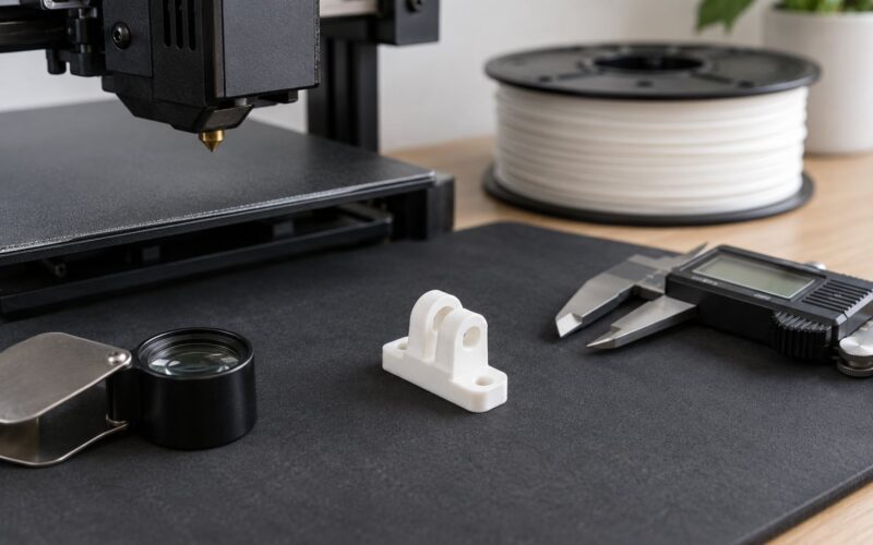
- A bright light and a magnifier, or your phone camera zoomed in. Half of first layer diagnosis is visual and you need light.
Exact controls differ by printer and firmware. A printer with a load cell probe has a guided calibration flow, one with a BLTouch or PINDA sensor has a probe offset, and a probe-less printer only has screws and a paper test. What stays the same across all three is the sequence and the target you’re aiming for.
One safety note before you start: never reach near the nozzle with bare fingers while the hotend is heated, and never move the bed or nozzle by hand during a print. If your printer has a heated bed, wait for it to cool below around 30 C before handling the plate bare, or use the plate’s lift.
Step-by-Step: First Layer Calibration Step by Step
1. Prepare the Printer and Build Plate
Start with the printer on a firm, level surface and the plate seated flat on all its locating pins or magnets.
This is the pre-flight step that most guides skip, and it’s where a surprising share of failures live. A plate cocked up on one locating pin guarantees a first layer that grips on one side and floats on the other. Prusa support staff call this out specifically when users report first layer problems, and it takes ten seconds to check.
Then clean the plate for the surface you actually have:
| Build plate surface | Cleaning method | Notes |
|---|---|---|
| Glass or smooth PEI | 90%+ isopropyl alcohol, wipe with a lint-free cloth | PEI holds heat better than glass, so a slightly hotter bed is fine here |
| Textured PEI | Dish soap and warm water, rinse, dry fully | IPA can leave a film that hurts adhesion on textured powder-coated sheets |
| Spring steel with plastic coating | Warm soapy water only | No solvents at all; they attack the coating |
| Garolite or other porous sheet | Brush off debris, wipe with a damp cloth | Never soak a porous surface |
Handle the plate only by the edges. Skin oil is enough to kill adhesion in one small spot, and that spot becomes the corner your part peels off from.
Now level the bed. On a manual printer, heat the bed and hotend, then use the four corner screws and the paper test to get all four corners within about 0.02 mm of each other. On a probe printer, run the manufacturer’s leveling routine first, and if the printer runs Marlin or Klipper, run the tram command before trusting the mesh.
Expected result: four corners at roughly equal height, plate clean and dry, bed level. If anything here is off, fix it now rather than later.
2. Set Material and Printer Conditions
Set your real nozzle temperature, bed temperature, layer height and initial line width before you test, because calibration only works at the conditions you’ll actually print in.
This is where most people get it wrong. A test square printed on a cold bed tells you almost nothing, because the nozzle and the frame both move as they heat up. Thermal expansion during a typical PLA warm-up shifts the nozzle by roughly 0.05 to 0.10 mm, which is two to five times the size of the adjustment you’re trying to make. Calibrate hot, at temperature, or you’re calibrating a printer that doesn’t exist.
Use these as starting points, not gospel. Filament brands vary by 10 C or more.
| Material | Nozzle | Bed | First layer speed | Adhesion aid |
|---|---|---|---|---|
| PLA | 200-215 C | 55-60 C | 20-25 mm/s | Usually none on a clean PEI sheet |
| PETG | 235-250 C | 70-80 C | 15-20 mm/s | Thin glue stick, or lower Z-offset on textured PEI |
| ABS / ASA | 240-260 C | 95-110 C | 15-20 mm/s | Glue stick; enclosure strongly recommended |
| TPU | 225-240 C | 40-50 C | 10-20 mm/s | Textured PEI; raise Z-offset slightly |
Keep the first layer height small. 0.20 mm with a 0.4 mm nozzle is a good default, and going wider than about 0.28 mm makes the layer harder to flatten evenly. Set the initial layer line width to roughly the nozzle diameter plus a bit, which for a 0.4 mm nozzle is around 0.45 to 0.50 mm.
Two settings people forget: keep the part cooling fan off for the first layer and usually the two after it, and turn off any wipe or purge that happens at the start of the print if your printer has a prime line option, so it doesn’t smear across the sheet.
3. Inspect the Nozzle for Extrusion Problems
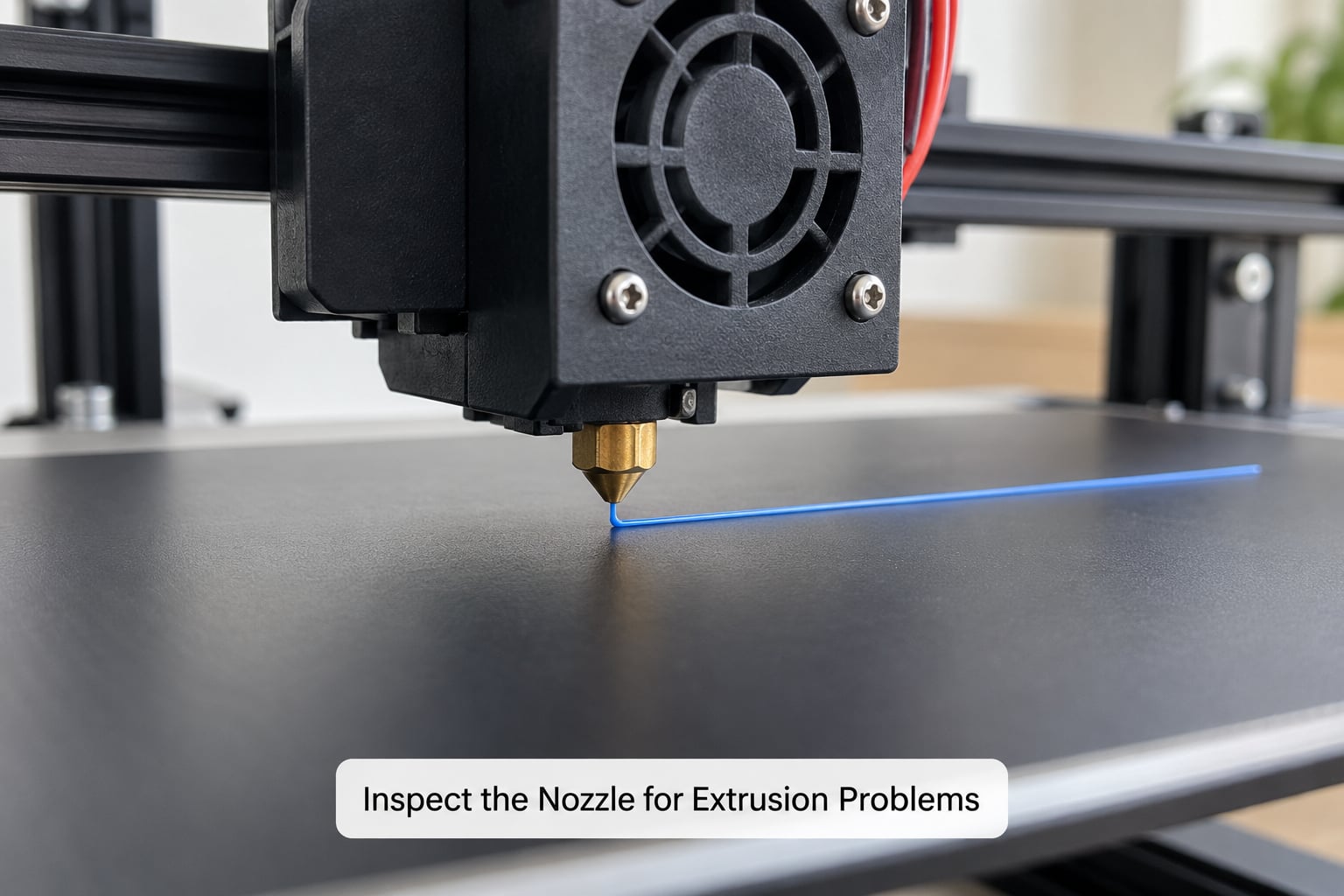
Check that the nozzle is actually delivering plastic before you touch any offset setting.
Run a short extrusion or a single-line extrusion test and look at the bead. A healthy bead is round, matte and consistent in diameter. A lumpy bead with blobby spots means ooze or a partial clog. A bead that thins out mid-line means under-extrusion. Blobs and zits on a first layer are an extrusion problem, not a Z-offset problem, and no amount of lowering the nozzle will fix them.
Clear a clog the way your hotend expects. On a direct-drive or Bowden machine, drop the temperature to about 190 C and push filament through with the cold pull technique or run a purge, then repeat your single-line test. A clogged nozzle also throws off your measurement of nozzle contact, because it stops laying down plastic at the gap you’re trying to measure.
Expected result: one clean line with even width, no gaps, no blobs. Anything else goes away before you continue.
4. Run a Nozzle-to-Bed Clearance Test
A clearance test tells you the direction to move: which way the offset has to go.
There are three routes, and they are not interchangeable:
- PrusaSlicer’s built-in tool. Open the Calibration menu and run First Layer Calibration. The nozzle moves next to the sheet, prints a line, and the wizard walks you through it. On an MK3S or MK4S this saves the result to the printer automatically.
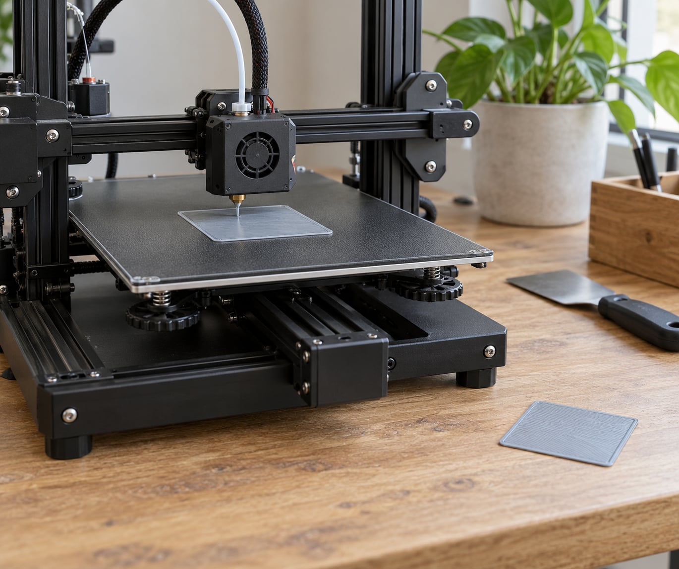
- Cura or Lychee. Slice a single-layer square — 75 x 75 mm at 0.20 mm layer height, no supports, no infill — and print it. Then read the result and adjust by hand in the printer’s Z-offset menu.
- Probe-less printers. Print the same single-layer square after your paper-level, then fine-tune with the paper method described in step 5.
Read the print like this:
- Visible gaps between lines — nozzle is too high. Bring the nozzle closer.
- Lines merged with a rippled, sandpaper texture — nozzle is too low. Raise it slightly.
- Smooth, flat, faintly shiny sheet where the lines merged with no ridges — that’s the target.
- One side sticks and one side doesn’t — this is tramming, not Z-offset. Go back to step 1.
Expected result: you now know the direction to move and roughly how far.
5. Adjust Z-Offset or Paper Spacing
Move the offset in small steps: 0.02 mm per attempt, and up to 0.04 mm if the first layer was badly off.
That increment is the answer to the most-asked question on 3D printing forums. People overshoot because nobody tells them the number.
How you make the adjustment depends on what you’re driving:
- Prusa MK3S / MK4S / XL: run First Layer Calibration in PrusaSlicer and use the on-screen controls, or use the Z-offset buttons on the printer’s LCD during the print.
- Bambu Lab: use the Z-offset raise/lower buttons in the calibration menu on the printer screen, then save the offset when prompted. The automatic first layer inspection gives you a starting point; the buttons are for the fine correction.
- Klipper:
SET_GCODE_OFFSET Z_ADJUST=0.02raises the nozzle by 0.02 mm,SET_GCODE_OFFSET Z_ADJUST=-0.02lowers it. Confirm withSAVE_GCODE_STATEonce you’re happy. UseSCREWS_TILT_CALCULATEfor tram first. - Marlin: use the Z-offset entry in the LCD Tune menu, or run M600 if you have a probe or BLTouch installed.
- No probe at all: use a controlled paper test. Heat the hotend and bed, run a single-line print at full Z-offset, lower Z until the nozzle just barely drags the paper when you move it, then back the adjustment off by about 0.1 mm. Re-run the single-layer square to confirm, because the paper test alone is an approximation.
Menu names and positions shift between firmware versions, so look for the Z-offset or “First Layer Calibration” entry rather than hunting for an exact path.
Expected result: a single-layer print where the lines merge into one sheet with no gaps and no ridges.
6. Calibrate Extrusion or First-Layer Flow
A perfect offset with wrong flow still produces a bad first layer, because the first layer carries the largest single line width in the whole print.
Measure it on your single-layer square. Hold the square up to a light or lay it on a flat surface and look at it. Uniform matte appearance means the flow is close. Bright lines that catch the light, or visible ridge outlines where each bead sat, mean over-extrusion. Narrow lines with a faint weave showing between them mean under-extrusion.
Fix it in this order: the slicer material profile first, since a badly tuned profile explains a lot. Then flow rate or extrusion multiplier — PrusaSlicer uses flow ratio, Cura and Lychee use flow rate, both multipliers on the profile’s extrusion value. If you haven’t set E-steps yet, do that first; a wrong E-step makes every flow number you enter meaningless.
Leave pressure advance and retraction alone until the first layer is right. They’re not first layer settings and they won’t fix a gap on the bed.
Expected result: the first-layer test square has an even finish from edge to edge.
7. Print and Verify a Full Test Pattern
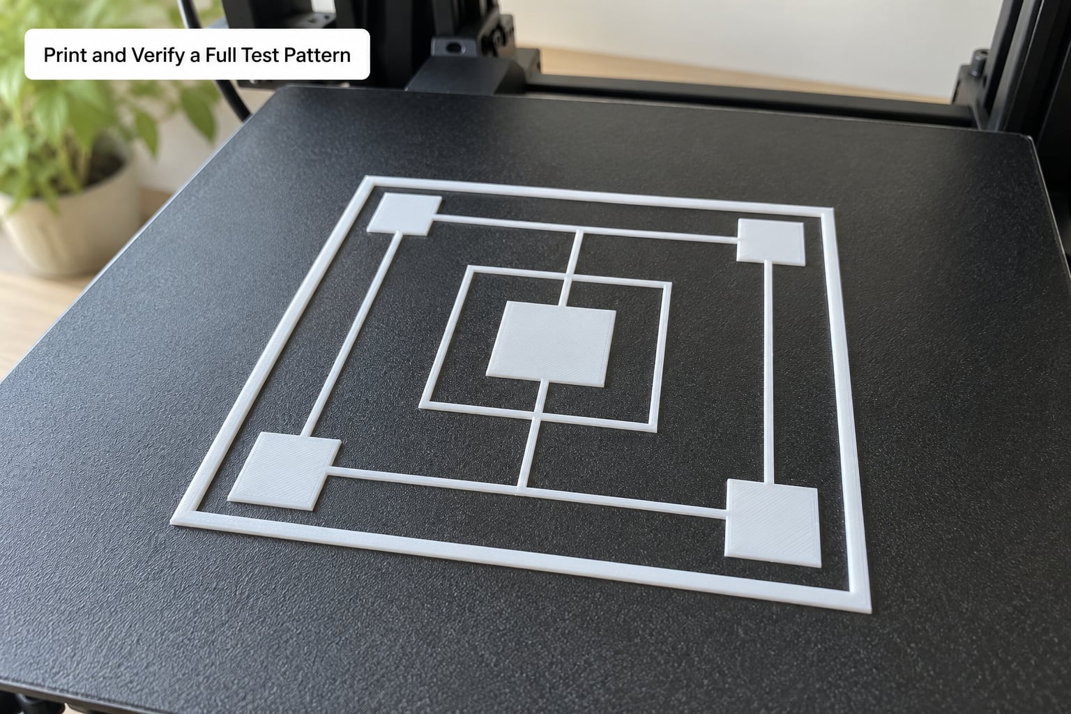
Run one full pattern that covers lines, filled areas and corners before you trust the setting.
A single square tells you about flow. It doesn’t tell you whether one corner is lower than the others, and corners are where failed parts start lifting. Print a pattern with three single-layer squares, a set of straight lines at different widths, and one solid filled square. Free calibration models are widely available on printer community model sites, and slicer-bundled test objects do the same job.
Check four things:
- Lines across the middle of the plate and along the edges, to catch tilt.
- All four corners of each square, which is where tramming shows.
- Surface evenness between the squares, which shows flow problems.
- Whether the sheet stays attached when you touch an edge — flex it gently with your fingernail. If it lifts, the bond is too weak.
Then save the setting. Note the Z-offset value, the plate type, the material and the nozzle size somewhere you can find later, because the value is only valid for that combination. Add a brim if you’re printing something large in PLA or PETG, and consider an elephant foot compensation of 0.15 to 0.2 mm if the bottom edge bulges.
Expected result: every square is flat, all corners grip, and the whole pattern stays on the plate.
Common Mistakes
Most first layer failures are one of a handful of things. Find your symptom below, then fix it in the priority order given.
| Symptom | Likely cause | Fix, in priority order |
|---|---|---|
| Visible gaps between lines | Nozzle too far from the bed | Lower the Z-offset 0.02 mm and reprint; confirm the bed is actually level |
| Ridges and a sandpaper-like texture | Nozzle too close | Raise the Z-offset 0.02 mm; check you’re not compensating with slicer first layer height |
| Lines stuck to the nozzle, first layer curls upward | Nozzle too close plus a cold bed | Raise the Z-offset, then raise bed temperature |
| Part peels off at one corner | Bed not level, or plate off its locating pins | Re-level, seat the plate on all pins, then re-run the mesh |
| Part peels off halfway through the print | Bed too cool, or first layer printed too slowly | Raise bed temperature, confirm adhesion, add a brim |
| Blobs and zits on the first layer | Oozing or a partial nozzle clog | Clean the nozzle, lower nozzle temperature 5 C, raise Z-offset |
| Rough, uneven thickness across one line | Under- or over-extrusion | Verify E-steps, then tune flow rate |
| Edges curl and lift away (warping) | Drafts, cold bed, or ABS without an enclosure | Raise bed temperature, add an enclosure, reduce first layer speed |
| Bottom edge bulges outward (elephant foot) | Over-squish or too much heat at the start | Raise Z-offset 0.02 mm, add elephant foot compensation |
| Stringy strands across the sheet | Retraction too low for the distance, or hot nozzle | Tune retraction, lower nozzle temperature, clean the nozzle between tests |
| Good calibration square but failed real prints | Tested cold, or with a different plate or material | Recalibrate hot with the plate and filament you’ll actually use |
| Works on glass, fails on textured PEI | Textured surface needs a different offset | Raise the Z-offset 0.04 to 0.08 mm for the textured sheet and re-test |
One trap deserves calling out on its own: raising the first layer height in the slicer to force adhesion. It usually makes the layer thicker without fixing the gap, and you end up with a wobbly bottom. Fix the offset instead.
Calibration Tips for Reliable Results
Change one thing at a time, and give each change one test square.
The fastest way to lose an afternoon is adjusting the offset, the bed temperature and the first layer height together, then having no idea which one helped. Make one change, print the square, look, decide.
Keep the filament dry. Wet filament pops and bubbles on the first layer, and the gaps look exactly like a Z-offset problem. If your square has bubbles or popping noise, dry the filament before you touch any calibration setting.
Clean between tests, and don’t handle the plate with bare fingers mid-session. A thumbprint near where you’re testing is enough to make a good offset look bad.
Repeat the test twice before you commit. A single good square can be luck, especially on a warped plate.
And recalibrate when the setup changes, not on a schedule. Change any of these and redo the process:
- Nozzle diameter, for example swapping a 0.4 mm for a 0.8 mm. A probe’s reference point changes too, so a probe printer may need its sensor position adjusted before the first layer test.
- Build plate, including swapping PEI sheets or going from smooth to textured.
- Filament type or brand, since wetness and flow vary between spools.
- Printer location, or any time you re-level or loosen the bed.
- Hotend or heater replacement, which changes thermal expansion behaviour.
A 10 to 20 minute recheck at the start of a print session is worth it. A full recalibration every print is not.
Frequently Asked Questions
Do I need to calibrate the first layer every time I start a print?
No. A full first layer calibration is only needed after you change the nozzle, the build plate, the filament type, or after moving or re-leveling the printer. For routine printing, run a quick single-layer square at the start of a session, read it, and adjust 0.02 mm if the lines are gapped or ridged. It takes two minutes and catches most problems before a multi-hour print starts.
What Z-offset gives a good first layer?
There is no single number, because the right value depends on your printer, nozzle and build plate. Aim for the visual target instead: the lines merge into one continuous sheet with no gaps between them and no rippled ridges or sandpaper texture on top. With a 0.4 mm nozzle and a 0.20 mm layer height, most printers land somewhere around minus 0.02 to minus 0.10 mm relative to the nozzle touching the plate.
Should I use a paper test or the printer’s Z-offset calibration?
Use the printer’s built-in calibration if you have a probe, load cell or sensor, because it measures the actual nozzle-to-bed distance and can store the result. Use the paper method only on probe-less printers, and treat it as a starting point rather than a final answer. Either way, confirm with a printed single-layer square, since paper thickness and feel vary between people.
Why does my first layer stick but later layers separate?
That is a layer adhesion problem, not a first layer problem. The usual causes are a nozzle temperature too low for the material, flow rate set too low, or filament that has absorbed moisture. Check your temperature tower results and make sure E-steps are calibrated, then look at the cross-section of a failed print to see whether the gap sits between layers or at the base.
Do I need separate first-layer settings for PLA and PETG?
Yes, and the difference is significant. PETG usually needs a hotter bed around 70 to 80 C, a slower first layer near 15 to 20 mm/s, and often a thin glue stick for adhesion on smooth PEI. It also usually wants a Z-offset 0.02 to 0.05 mm higher than PLA because PETG flows wider. Calibrate each material separately and record both offsets.
Why are the corners of my first layer worse than the straight lines?
Corners expose bed tilt, because the nozzle is the only thing touching the plate there and any height difference changes the gap sharply. Straight lines average out the error across their length, which hides it. Fix tramming first: check the plate is seated on all its locating pins, run the leveling routine, and on Klipper use SCREWS_TILT_CALCULATE before touching the offset at all.
Conclusion
Start where most people skip: clean the plate properly, make sure it’s seated flat on all its pins, and confirm the nozzle is extruding a clean line with no blobs or gaps. Then heat the printer to real print temperature, run a controlled thin-line or single-layer square, and adjust the offset by 0.02 mm in the direction the result tells you.
Record the value against the plate and material you used, and redo the process only when the nozzle, plate, filament or printer position changes.