A hearing aid shell is the custom outer housing of an in-the-ear device, shaped to the exact geometry of one wearer’s ear canal so it can hold the receiver, battery and electronics while sealing acoustically. Understanding how hearing aid shells are 3D printed matters if you have ever wondered why modern custom devices no longer come from a hand-poured acrylic mould. The short version: the ear is captured as data, the shell is designed in CAD, and the part grows layer by layer in resin, ceramic or metal, then gets finished, inspected and fitted by a hearing professional.
Additive manufacturing did one thing better than injection moulding here, and that was removing the mould. No die, no subtractive drilling, no remoulding wax pattern. What remains is a digital thread from scan to shell that runs on a single workstation for a single patient.
The rest of this guide walks that thread stage by stage, including the printing processes, the materials, the finishing work, and the point where the process belongs firmly in the hands of clinics and regulated labs rather than a kitchen table.
Table of Contents
- How Hearing Aid Shells Are 3D Printed
- The six stages of shell production
- Why Hearing Aid Shells Are Made Digitally
- How the Ear and Intended Device Are Scanned
- How the Shell Is Designed in CAD
- Which 3D Printing Process Is Used?
- SLA and DLP for resin shells
- SLM, LCM and MJF for premium and non-clinical routes
- What Materials and Print Settings Matter?
- How the Printed Shell Is Finished
- How Quality Is Checked Before Fitting
- Where the Process Is Still Done by Professionals
- What a maker can reasonably print at home
- Frequently Asked Questions
- Can I 3D print a hearing aid shell at home?
- What 3D printer is best for hearing aid shells?
- Are 3D printed hearing aid shells safe?
- How accurate must a hearing aid shell scan be?
- What material is used to 3D print hearing aid shells?
- Does a 3D printed shell replace a hearing aid fitting appointment?
- Conclusion
How Hearing Aid Shells Are 3D Printed
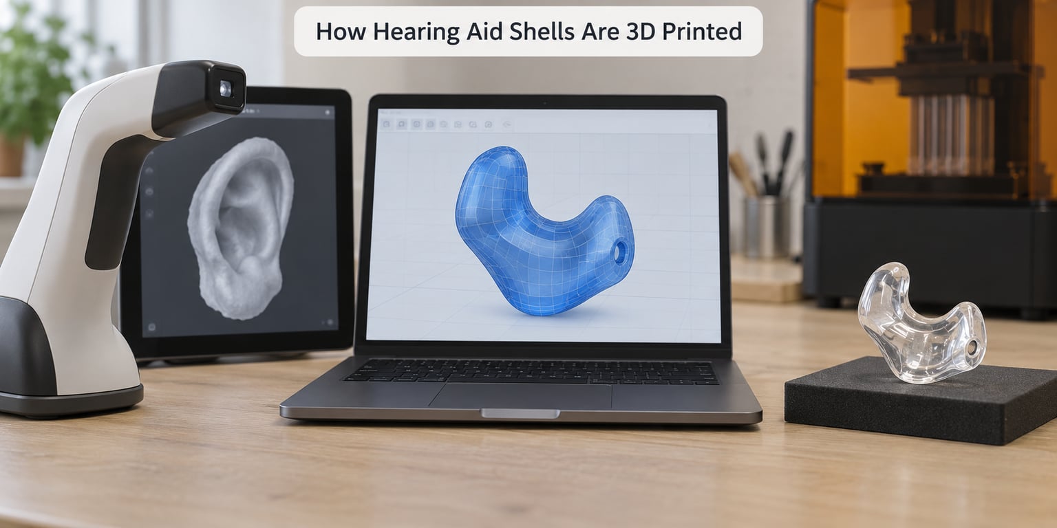
Six stages cover it, and each one has a failure mode worth knowing about. The order matters more than the technology: a flawless print built from a sloppy scan still fits badly.
The six stages of shell production
- Capture. The ear is recorded as a silicone impression or, more often now, as a 3D scan taken with an intra-ear scanner. Both become a digital file, but the scan carries surface data the impression cannot.
- Digital modelling. The scan is imported into CAD software, cleaned, oriented and aligned with the specific hearing device being built, so the shell knows where the receiver, microphone and battery sit.
- Design customisation. Vents, receiver channels, acoustic chambers and wall thickness are drawn in at this point. This is where additive manufacturing earns its keep, because features a mould cannot hold can simply be modelled.
- Printing. The model is sliced and printed. Vat photopolymer processes, meaning SLA and DLP, dominate for resin shells. Powder bed fusion such as SLM handles titanium, and LCM handles ceramics.
- Post-processing. The part comes off the platform dirty and unfinished. It gets washed, post-cured, depinned, deburred, polished and dried before anyone looks at it closely.
- Quality control and fitting. Dimensions, venting, finish and acoustics get checked, then a hearing care professional fits the device to the ear and validates the result with measurements.
That is the whole workflow. Everything else in this article is detail on one of those six lines.
Why Hearing Aid Shells Are Made Digitally
The reason to model a shell digitally is control over fit. A canal is not a generic hole, so a part made for an average ear is a part that will loosen, press or leak in a real one. Digital capture measures the specific geometry instead of approximating it through a physical impression that is cast, shrunk and handled before anyone designs around it.
Comfort follows from that. A shell that matches the canal walls distributes pressure rather than concentrating it at a few contact points, which is what causes sore spots after hours of wear.
Acoustic positioning is the quieter reason. The receiver has to sit at a specific depth and angle for the amplified signal to arrive at the eardrum the way it was programmed to. Small geometric errors show up as feedback, a plugged sensation, or output that simply does not match the settings.
Repeatability matters too. Once a design is validated, the same file can be reprinted, and a change to vent geometry can be tested without re-cutting tooling. Collaboration is the practical benefit: audiologists, manufacturers, and digital designers all work from the same file rather than a paper description and a physical mould in the post.
One distinction worth keeping straight. A shell is the housing. It is not the hearing aid. The device inside carries the microphones, amplifier, battery and receiver, and it is a regulated medical product. The shell is a custom component that holds it and seals the canal, and a printed shell does not turn an untrained object into a fitted hearing aid.
How the Ear and Intended Device Are Scanned
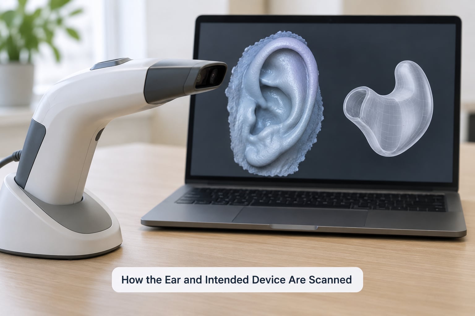
Scanning starts with the same clinical step an impression would require: a careful look at the ear canal, removal of wax or obstruction, and confirmation that nothing is inflamed. A file that faithfully records a blocked canal faithfully reproduces the blockage.
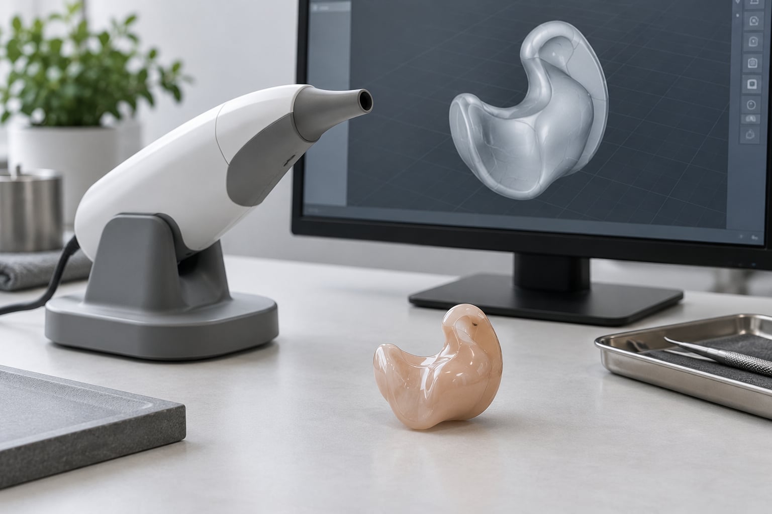
The scanner sits in the ear and sweeps a structured light or laser across the canal surface, collecting a few thousand or a few hundred thousand points and converting them into a continuous surface mesh. Nothing about the anatomy is approximated by hand, which is the main reason scan-based shells produce fewer remoulds than cast impressions.
Pre-scan preparation matters as much as the hardware. The canal is dried and inspected, the scan is checked for holes or smeared regions, and reference landmarks such as the canal entrance and the tragus position are recorded so the model can be aligned later.
Then there is the part people forget. A scan describes an ear, not a device. The file has to be registered against the specific hearing aid being fitted, because receiver diameter, battery position, venting requirements and shell style vary between models and power levels. Skip that alignment and you get a beautifully accurate scan of an ear fitted to the wrong hardware.
How the Shell Is Designed in CAD
Design starts with cleanup, not drawing. Scan data arrives as a mesh with noise, and the first job is removing artefacts, filling small holes, and orienting the surface so the canal axis runs predictably through the model.
Next comes alignment with the device. The CAD software loads the component library for the hearing aid in question, and the model is positioned so the receiver channel, microphone port and battery compartment all line up with what will actually be installed. If the design is being cut down to a very small size, such as a completely-in-canal or invisible-in-canal style, that clearance work gets tighter with every millimetre removed.
Vents get drawn next, and they are the quiet reason custom shells sound better than generic ones. An ear canal vents to skin pressure, and a sealed canal produces the occlusion effect, the plugged or booming quality users complain about most. Sub-millimetre vents relieve it while the acoustic seal handles feedback control, a balance that is hard to hit in a moulded part with drilled holes.
Wall thickness is where the process earns its second advantage. Resin shells can be built with walls thin enough to stay unobtrusive, and titanium shells are commonly reported at roughly half the thickness of equivalent acrylic parts. Thin does not mean weak: sections carrying electronics are thickened while comfort-critical areas stay slim.
The last step is validation against the manufacturer’s specifications. Wall minimums, vent positions, receiver clearances and material limits all come from the device maker, not from taste. A model that ignores them can print perfectly and still be unassemblable or acoustically wrong.
Which 3D Printing Process Is Used?
The process depends on material, resolution, design, volume and validation requirements. For most custom hearing aid shells, it is vat photopolymerisation: a liquid resin cured layer by layer by light.
SLA and DLP for resin shells
SLA, stereolithography, uses a UV laser steered by galvanometer mirrors to cure one point at a time. DLP, digital light processing, projects an entire layer at once through a digital mirror device. Both produce the smooth, non-porous surfaces a canal needs.
Layer thickness in the 25 to 50 micron range is typical for this work, which is fine enough that a sub-millimetre vent stays open after printing. A layer-line finish that looks like fine sandpaper under a loupe is still too coarse for direct skin contact, which is why polishing is not optional.
FDM, the material-extrusion process most home printers run, is a poor fit for a shell. Visible layer ridges sit directly against sensitive canal skin, and the seam lines cause pressure points. It can be used for rough fit prototypes, which is genuinely useful, but not for a wearable part.
SLM, LCM and MJF for premium and non-clinical routes
SLM, selective laser melting, prints titanium powder with a laser and produces premium thin-wall shells, at the cost of dedicated support removal, debinding and post-machining of sprues.
LCM, lithography-based ceramic manufacturing, works like DLP but with a ceramic slurry. Printed parts are green bodies at that stage, and they go through debinding and sintering before they become a finished hard shell. Sintering is where the four to five day lead time comes from, and where shrinkage must be accounted for in the design. A material like alumina-toughened zirconia lands in this category.
MJF, multi-jet fusion, and SLS appear mainly in non-clinical and production-moulding work, such as custom hearing protection and silicone ear defenders where a printed mould is cast into the final part. Reportedly around 30 earmoulds fit in a typical print run, with several runs a day on a production machine.
What Materials and Print Settings Matter?
Resin choice is a safety decision, not a finishing one. A shell that sits against canal skin all day should come from a formulation with documented biocompatibility. Standard draft resins optimised for strength or toughness can contain uncured acrylates and irritants, and the marketing term for a safe one is usually biocompatibility certification, not a strength rating.
For people who react to acrylic, that choice is the whole reason to stay in the conversation. Titanium and ceramic routes exist precisely because a small number of patients cannot wear acrylate against the canal, and hypoallergenic is the word that matters to them.
Surface finish is the other patient-facing variable. A dense, non-porous shell does not hold earwax in its pits, and a smooth canal surface is easier to keep clean. Porous surfaces are a common complaint, because they collect cerumen and become harder to clean over time.
| Material | Process | Wall thickness | Biocompatibility | Surface finish | Typical use |
|---|---|---|---|---|---|
| Injection-moulded acrylic (baseline) | Injection moulding | Standard, relatively thick | Good, but acrylate sensitivities occur | Smooth, polished | Legacy shells and mass-market devices |
| Photopolymer resin | SLA or DLP | Thin, 25 to 50 micron layers | Varies by formulation, choose certified biocompatible resin | Fine layer lines, needs polishing | Most custom in-the-ear shells and earmoulds |
| Titanium | SLM powder bed fusion | Very thin, roughly half an acrylic equivalent | Hypoallergenic, ideal for acrylate reactions | Matte metal, often finished | Premium and allergy-driven fittings |
| Alumina or alumina-toughened zirconia | LCM then sintering | Thin after sintering shrinkage | Very good, inert and easy to clean | Naturally white or translucent | Premium earmoulds, cosmetically driven orders |
Print settings matter just as much. Orientation decides where supports land, and supports on a functional surface leave marks exactly where the canal will feel them. Rounded shell forms print cleanly because they present a consistent angle to the light, while sharp internal edges concentrate stress and can crack. Printers in this field report support-free designs wherever geometry allows, and roughly a thousand shells in a furnace batch for ceramic work, which is where batch economics start to matter.
How the Printed Shell Is Finished
A part straight off the platform is not wearable, and the gap between printed and wearable is where most home attempts end.
Supports come off first, then the part is washed in solvent, often ultrasonically, to strip residual resin. Freshly washed parts are still soft and easy to distort, so handling matters more than most people expect. Warping shows up here first.
Post-curing follows under UV light, sometimes in a heated chamber. This completes the polymerisation that stabilises the material and locks in the final hardness. A part that is not fully cured can feel fine and then change shape or properties weeks later.
Finishing is the stage that decides comfort. Support marks get sanded away, edges are deburred, and the canal surface is polished smooth enough that a fingernail cannot catch it. Colour, translucency or coating is applied at this point, which is also where cosmetic customisation happens, and user communities care about that far more than manufacturers assume.
Ceramic parts take a different route. They are debound and sintered, which converts the printed green body into a hard finished part, and shrinkage during that cycle has to be compensated in the original design. The shell is then cooled, inspected and labelled.
How Quality Is Checked Before Fitting
Inspection starts with the eye, under magnification, looking for the defects that matter in this application: cracks around sharp internal corners, porosity, leftover support scarring inside the canal, and any vent that did not open cleanly.
Then dimensions get checked against the CAD model, since a shell that misses its receiver channel clearance will not assemble and one that is slightly undersized in the canal will not seat properly. Venting gets verified separately, because a blocked vent is invisible from outside and produces a fit that feels right but sounds wrong.
Receiver and microphone placement gets confirmed against the device that will go inside, along with the acoustic seal. If the seal is inconsistent, the user gets feedback or unstable gain, and the fix is the shell, not the programming.
Documentation closes the loop. Scan file, CAD model, print batch, resin lot and inspection result all get recorded, which is what allows a problem to be traced and a repeat order to reproduce the first one. The final assessment is not a technician’s. Real-world checks, insertion, comfort, feedback behaviour and hearing performance belong to a hearing care professional, and that appointment is part of the process rather than an optional extra.
Where the Process Is Still Done by Professionals
Printing is only one link in a regulated chain. A hearing aid shell for a fitted device is a component of a medical device, and the device itself must be dispensed, fitted and validated by a qualified hearing care professional. That person also owns the parts of the process printing cannot help with: ear assessment, device selection, programming and follow-up.
Manufacturers hold the material specifications and the component libraries that a valid shell design depends on. Labs and production partners hold the validated print settings, the biocompatibility documentation and the inspection records. A shell produced outside that system can be a fine object and still be unsuitable for clinical use, which is a different problem from being badly made.
What a maker can reasonably print at home
Printing is legal. The restriction is not about the printer, it is about what the part is for and who fits it.
Reasonable home projects include non-clinical earmoulds for hearing protection, ear tips and domes, custom in-ear monitor shells for personal use, display pieces showing off colour and shape, and fit prototypes used to check proportions before anything clinical happens. Visible, cosmetically styled shells built purely as a design exercise are a well-established maker project.
Risky ground includes anything intended to amplify sound. Shell geometry affects feedback, occlusion and output in ways that are not obvious from the outside, and a poor fit can cause real discomfort or skin damage. If you are experiencing hearing loss, get assessed before you experiment, and treat any printed result as a prototype rather than a device.
There is a practical reason for the boundary as well as a legal one. Clinics and labs can compare scans against validated specifications, catch a bad fit before it reaches an ear, and stand behind the result. A kitchen printer can do none of that.
Frequently Asked Questions
Can I 3D print a hearing aid shell at home?
Yes, you can print a shell at home for non-clinical uses such as personal earmoulds, ear tips, custom in-ear monitors or a display piece. What you cannot do is treat it as a fitted hearing aid. Amplification, feedback control and real-ear validation need a hearing care professional, and a poor canal fit can cause discomfort or skin irritation.
What 3D printer is best for hearing aid shells?
Desktop SLA or DLP resin printers are the practical choice, because they resolve sub-millimetre vents and thin walls at 25 to 50 micron layers. FDM is fine for rough fit prototypes but its seams irritate canal skin. Titanium shells need SLM powder bed fusion and ceramic shells need LCM followed by sintering, neither of which is a home machine.
Are 3D printed hearing aid shells safe?
They are, when they are printed in a biocompatible resin and finished properly. The risks come from ordinary mistakes: uncertified resin with uncured acrylates, an incompletely cured part, support scarring left inside the canal, or rough surfaces that trap earwax. Polishing, full post-curation and professional fitting address all four.
How accurate must a hearing aid shell scan be?
Accurate enough to describe the canal without holes, artefacts or missed landmarks, and registered against the exact hearing device being fitted. A flawless scan modelled for the wrong receiver position still produces an unusable shell. Scan quality also drives remould rates, which is why clinics check the file before sending it to the printer.
What material is used to 3D print hearing aid shells?
Most shells use biocompatible photopolymer resin printed by SLA or DLP. Premium routes use titanium powder with SLM, or alumina and alumina-toughened zirconia with LCM plus sintering. Standard draft resins are not appropriate for skin contact, and acrylate sensitivities are the main reason patients move to titanium or ceramic.
Does a 3D printed shell replace a hearing aid fitting appointment?
No. Printing removes the mould, not the clinical work. Ear assessment, device selection, programming and real-ear validation still need a hearing professional, and a printed shell fitted without them is an experiment rather than a device. The appointment is what turns a well-made part into a working hearing aid.
Conclusion
The pipeline is short once you know it: scan the ear, model the shell in CAD, design the vents and channels, print in resin, metal or ceramic, finish it, inspect it, and fit it. Additive manufacturing made every shell unique and pushed walls thinner at the same time.
The first practical step is the scan. If you want to understand the process hands-on, start by capturing a digital impression and modelling from it, then work with a hearing professional and validated manufacturing specifications for anything that will actually be worn.