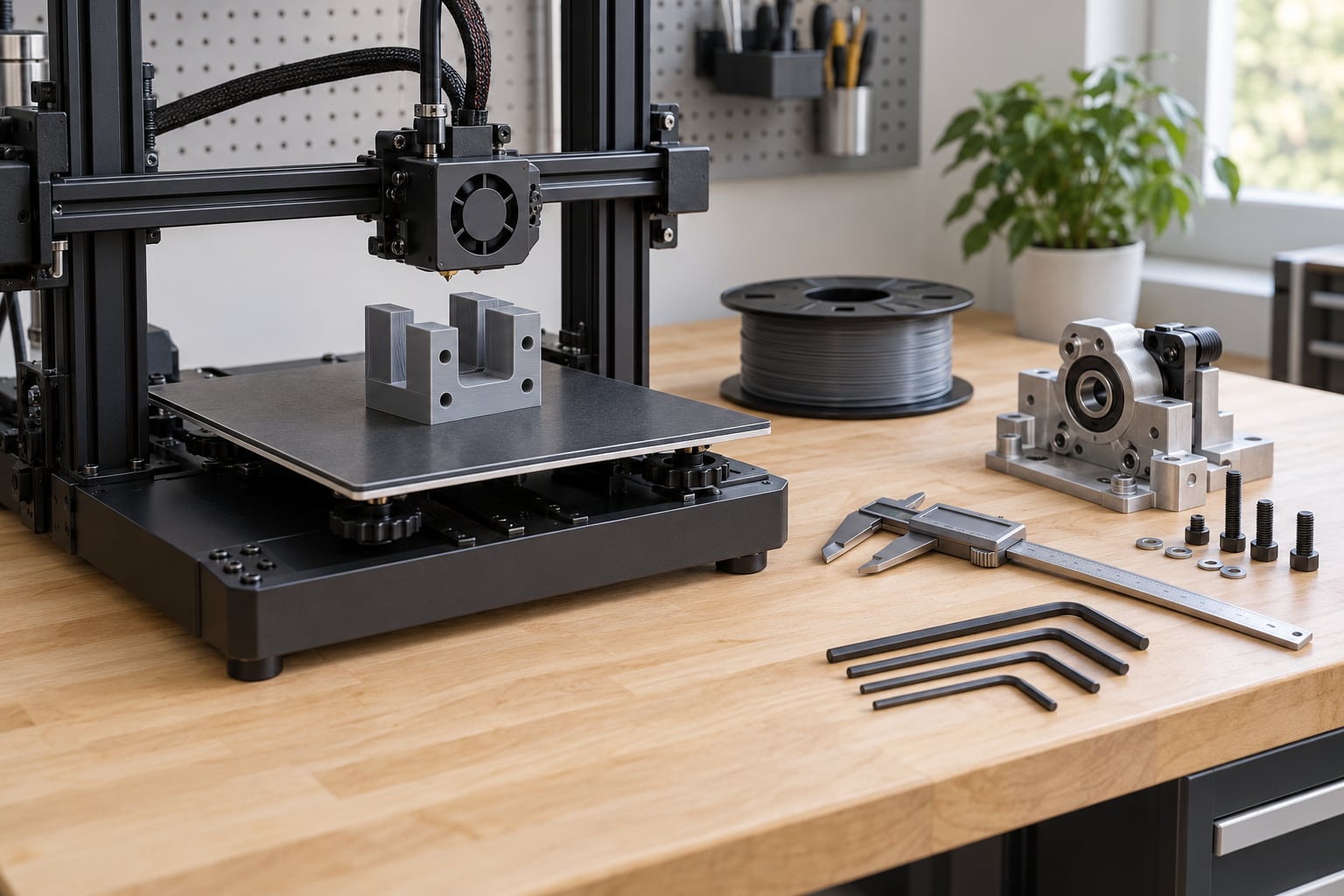
A jig guides a tool or a hand to a repeatable position, and a fixture holds and locates a workpiece so it does not move. Both are ideal candidates for printing when you need one to five of them and no supplier sells your version. The process is straightforward once you stop treating a printed jig as a plastic prototype and start treating it as tooling with tolerances.
Most first attempts fail for the same reason: nobody measured the part, so the model guessed. Get a caliper on the real workpiece, model a body around it with deliberate clearance on every locating feature, and the rest of this walkthrough takes an evening rather than a week.
Table of Contents
- What You Need
- Step-by-Step: How to Print Custom Jigs and Fixtures
- 1. Define the Jig’s Job and Capture Accurate Measurements
- 2. Choose a Design and Printing Process
- 3. Model a Fit That Can Be Adjusted
- 4. Select the Material and Print Settings
- 5. Print, Remove, and Finish the Part
- 6. Test, Iterate, and Document the Fixture
- Common Mistakes
- Frequently Asked Questions
- What is the difference between a jig and a fixture?
- How do I design a 3D printed drill jig?
- How much clearance do I need for a 3D printed screw hole?
- Is FDM or resin better for jigs and fixtures?
- What material should I print a jig in?
- Are 3D printed jigs and fixtures strong enough for real work?
- Conclusion
What You Need
Most of what you need is already on a bench. The list below is what a first custom jig genuinely requires.
- Design references — the real part, a drawing if one exists, or a scan of it. If the part is legacy equipment with no CAD, a 3D scanner or careful caliper work gives you the geometry to model around.
- Measuring and marking tools — digital calipers for the part and the finished print, plus a machinist square, a centre punch, and a scribing tool for marking datums on the real part.
- CAD — a parametric modeller such as Fusion 360, SolidWorks, or Onshape. Browser-based CAD tools also work, and a STEP export gives you clean handoff if you start somewhere rough.
- A slicer — PrusaSlicer, Cura, or OrcaSlicer.
- A printer and material — an FDM machine with PETG or ABS/ASA covers most bench work. An SLA printer gives better fit accuracy and surface finish if you have one.
- Cleanup equipment — a deburring tool, flush cutters, files, and a small brush or drip tray.
- Real hardware — M3, M4, or M5 socket head cap screws, heat-set brass inserts, 3 to 4 mm h8 dowel pins, and springs if you want a part to lift off the fixture easily.
- Test stock — a scrap of the actual workpiece material, or a sacrificial piece of the same geometry, to test fit before you trust the jig on real parts.
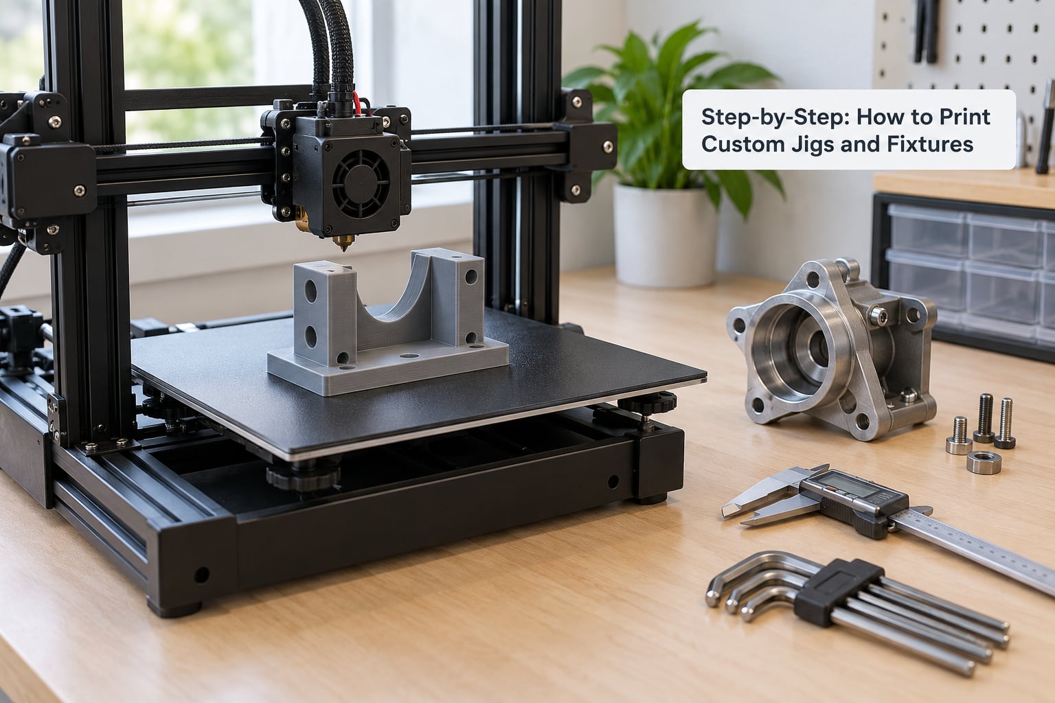
Step-by-Step: How to Print Custom Jigs and Fixtures
1. Define the Jig’s Job and Capture Accurate Measurements
Start by writing down exactly one job the jig does. A drill jig positions a bit at a marked location. A welding fixture holds two tubes at a fixed angle and spacing. A go/no-go gauge accepts or rejects a bore. A soft jaw grips a finished surface in a vice without marking it. If you cannot write that sentence in one line, you are designing two tools at once and the first print will disappoint you.
Then measure the real part, not a drawing of it. Take the dimensions that define the fit: hole diameters and their positions, the envelope of the part, the width of a tab, the depth of a pocket. Record the tolerances your application actually needs. For a positioning template that guides a bit, ordinary workshop accuracy is fine. For a gauge that has to accept or reject a part, you need tighter control and probably a better process than a commodity FDM machine.
Mark your datums on the real part with a scribe. The surfaces everything else is measured from. Those scribed lines will show up on your workpiece later, and a jig built around a datum that only exists in your head will never locate the same way twice.
Fit is only worth engineering when the assembly repeats. If a task comes up twice, just clamp the part. Printed tooling earns its keep when you will do the same operation dozens of times, or when hand-holding is producing scrap.
2. Choose a Design and Printing Process
Your process choice sets your tolerance budget, so decide it before you model anything.
FDM is the default for a bench-top jig. It is cheap to iterate, and PETG or ABS/ASA parts are stiff enough for positioning and guiding work. Its weak point is holes: they print undersized, and slots print oversized, consistently enough that you can design around it.
SLA resin is the right pick when fit accuracy and surface finish matter more than material toughness. A resin jig holds tighter dimensions and gives you a smooth surface that will not mark a workpiece. The trade is post-processing: wash, cure, and remove supports before you can measure anything.
SLS or other powder processes suit volume. When you need twenty identical assembly nests rather than one drilling template, nesting parts in a powder bed makes more sense than twenty FDM prints, and the parts come out usable with no support marks to clean off.
Print-in-place is tempting for a fixture with a moving element. It works for a light latch or a simple spring arm. It fails for anything that carries real clamping force, because the interface between the moving part and the body prints as weak infill unless you design a solid joint deliberately.
3. Model a Fit That Can Be Adjusted
Model a body around the part, not a copy of it. The jig needs three things: a base that registers against the workpiece, locators that prevent movement, and a feature that does the actual work — a bushing, a bore, a clamp pad, a template opening.
Give yourself adjustment before you give yourself precision. Slotted or elongated mounting holes let you shift a locator by a few millimetres after the first print. A pocket that accepts a shim or a washer gives you the same freedom in a different direction. Printed parts can be reamed or drilled by hand too, which turns a fixed error into a thirty-second correction.
Use real hardware wherever a printed feature would carry repeated load. Heat-set brass inserts hold far better than cut threads in plastic, and threads printed straight into a jig strip after a handful of uses. Alignment pins around 3 to 4 mm diameter, pressed into printed bores, do the locating work so your printed holes only have to be roughly right. Makers on r/functionalprint describe exactly this: buy h8 precision pins, print the bore at nominal size, and let the pin set the fit.
Add fillets everywhere a corner changes direction. A sharp internal corner is a stress riser and a place where layers separate. A 2 to 3 mm fillet costs almost nothing in filament and makes the part considerably tougher.
These clearance values are a sane starting point for a well-maintained FDM machine. Printed holes are almost always undersized, so the bias is deliberate.
| Fit type | Clearance (mm) | Clearance (inches) | Where it goes in a jig |
|---|---|---|---|
| Free sliding fit | 0.3 to 0.4 | 0.012 to 0.016 | Locating pin bores, guides that must move easily |
| Normal slip fit | 0.2 to 0.3 | 0.008 to 0.012 | Bolt clearance holes, general alignment features |
| Close fit | 0.1 to 0.2 | 0.004 to 0.008 | Bushings pressed into a jig body |
| Light press fit | Negative, drill or ream to size | Drill to size | Dowel pin seats, anything that must not shift |
Rather than trusting those numbers blindly, print a tolerance coupon. A simple plate with a row of holes at stepped diameters and a matching row of shafts tells you what your specific machine does to a hole, and it costs about twenty minutes of filament. The Ultimaker community pushes this hard for a reason: a measured coupon beats a guessed compensation value every time.
4. Select the Material and Print Settings
Pick material by load, temperature, and contact. Get the stiffness story right first, because geometry alone does not make a fixture rigid. A jig that flexes at the locating features will not hold a position, no matter how accurately you printed it, and that warning comes up constantly from people running printed fixtures on real work.
| Material | Best use in a jig | Key limitation |
|---|---|---|
| PETG | Default for bench jigs, drill templates, assembly nests | Creeps slowly under sustained clamping load |
| ABS / ASA | Workshop tooling, higher heat, UV exposure, outdoor use | Warps without an enclosure; needs good bed adhesion |
| Nylon (PA12) | Wear surfaces, repeated sliding contact, production aids | Absorbs moisture, prints fussy, dimensionally variable |
| TPU | Soft contact pads and grip faces that must not scratch | Too flexible to carry any structural load |
| Polycarbonate | High heat, clamping force, stiff load-bearing features | High print temperature, warping, expensive filament |
For a light-duty jig printed in PLA you will get a usable part, but know that PLA creeps under a constant bolt load and softens near a hot work surface. A printed fixture that has to be re-tightened every few cycles is a fixture with a design problem, not a material problem.
Set the slicer up for function, not looks. Use four or more perimeters for stiffness, since wall count buys far more strength than infill density at the same print time. Keep infill around 20 to 30 percent; going higher mostly costs hours. A 0.2 mm layer height is a sensible default for a fit-critical jig, and thinner layers only help marginally.
Set X/Y compensation from your measured coupon, not from a forum guess. If your holes come out 0.15 mm undersized, that is the number your slicer needs. Check elephant’s foot compensation too, because the first few layers bulge and can stop a bushing seating fully.
5. Print, Remove, and Finish the Part
Orientation decides whether the jig survives, because layer adhesion is the weakest axis of an FDM part. Load must run across the layer lines, not along them. A flat plate jig loaded in-plane is strong. The same plate stood on edge with the load splitting the layers will snap.
Put the datum and locating faces on the build plate when you can. Every support you add is a surface you have to clean up, and a support scar on a locating face is a fit error you did not ask for. Support interior bores and overhangs, and leave the working surfaces free.
Print a small test piece of the critical feature first if the jig is expensive in time. Ten minutes on a bushing or a single locator can tell you whether the fit is right before you commit to a fourteen-hour build.
Remove the part when the bed has cooled to room temperature. Pulling a warm ABS or polycarbonate part off the plate bends it, and a slightly bent datum means a jig that never quite seats.
Finish it gently. Break support material off by hand along the grain rather than levering with a knife, then flush-cut supports flush with the surface. File or sand edges, but keep your caliper nearby and never file a locating feature to fix a dimension. Change the model and reprint instead, because an unrecorded hand correction is lost the next time the file is needed.
6. Test, Iterate, and Document the Fixture
Measure the print against your model before the part touches your work. Check the critical dimensions with calipers: locator positions, bushing bore, base flatness, and any distance the operation depends on. If a measurement is out, work out which side of the nominal it missed and change the model accordingly.
Then do a real fit test on scrap stock of the same geometry. Slide the part in, check for rocking, and check that the jig locates in the same place after you remove and reseat it. That reseat test is the one that catches a bad datum.
Your first jig will be wrong in some small way. That is the process working, not failing, and a printed jig is cheap enough to iterate on. Change one variable at a time, keep the model parametric so a shift is a number edit rather than a redraw, and re-print only the part.
Finally, file it properly. Save the model, the slicer profile, the material, and the print orientation somewhere you will find them in two years, because a jig that cannot be reprinted when it breaks is a single point of failure on the bench. Emboss the part number and revision on the jig body itself, in a spot that will not interfere with the work. When you find a better version, print a new one rather than overwriting the old file.
Common Mistakes
Almost every first-iteration failure comes from one of seven causes, and each has a direct fix.
- Modeling from memory instead of measuring. Fix: caliper the real part first and record the numbers in the model’s parameters.
- Zero-clearance holes. Printed holes come out undersized and a bolt-hole jig binds on the first try. Fix: add 0.2 to 0.3 mm across the diameter.
- Guessing at machine tolerance. Fix: print a stepped tolerance coupon, measure it, and set X/Y compensation from the result.
- Poor orientation. Layer adhesion splits the part when the load runs along the layer lines. Fix: rotate the part so force runs across the layers, and add perimeter walls.
- Supports on datum surfaces. Support scars stop a part seating properly. Fix: orient the datums onto the build plate and support only interior bores and true overhangs.
- Cut threads in plastic. They strip, and the jig becomes scrap after a few uses. Fix: heat-set brass inserts, or print the hole undersized and drill and tap it.
- Unverified assumptions about repeatability. A jig that locates once is not yet a fixture. Fix: reseat the part three times and check it lands in the same place every time.
Two smaller habits prevent most repeat problems. Keep the fillet radius generous at every internal corner, and loosen clamping bolts after each operation, because printed fixtures relax slightly under sustained load and a fixture that creeps will not stay tight.
Frequently Asked Questions
What is the difference between a jig and a fixture?
A jig guides a tool or a hand to a repeatable position, such as a drill template or a router guide. A fixture holds and locates a workpiece so it does not move during work, such as a welding nest, an assembly tray, or soft jaws. Both are shop-floor tooling, and both print well when you need a small number of process-specific items that no supplier sells.
How do I design a 3D printed drill jig?
Measure the real workpiece with calipers, pick two or three features that define its position, and mark those as datums with a scribe. Model a body that registers against those datums, then add a bushing or bore at the drill location on the axis you need. Give the bushing 0.2 to 0.3 mm clearance, add fillets, and slot one mounting hole so you can shift position after the first print.
How much clearance do I need for a 3D printed screw hole?
Add 0.2 to 0.3 mm across the diameter of a clearance hole on a typical well-maintained FDM machine, because printed holes come out undersized almost every time. A 0.3 to 0.4 mm range suits locating pins and guides that need to slide freely. Print a stepped tolerance coupon and measure it first, since machines and slicer profiles differ enough that a general rule only sets your starting point.
Is FDM or resin better for jigs and fixtures?
FDM with PETG or ABS/ASA is the practical default for bench jigs because it is fast, cheap to iterate, and stiff enough for positioning work. Resin is better when fit accuracy and a surface that will not mark a workpiece matter, since you get tighter dimensions and a smoother surface at the cost of washing, curing, and support removal. Choose powder-bed printing when you need twenty or more identical parts.
What material should I print a jig in?
Use PETG for most workshop jigs, ABS or ASA where heat and UV matter, Nylon for wear surfaces and repeated sliding contact, TPU only for soft non-marking contact pads, and polycarbonate when you need real clamping force at high temperature. Avoid PLA for anything under sustained bolt load or near a heat source, because it creeps and softens and the jig will slowly lose its position.
Are 3D printed jigs and fixtures strong enough for real work?
Yes, when you think about stiffness and load path rather than geometry alone, which is the warning people who run printed fixtures on real jobs give most often. Add four or more perimeter walls, orient the part so force crosses the layer lines, and keep infill in the 20 to 30 percent range. Printed tooling is not the answer for heavy impact loading or high-temperature continuous service, but it is genuinely good at guiding, positioning, and inspection work.
Conclusion
Document the real assembly before you model anything: measure the part, scribe the datums, and write down the one job the jig does. Then model the simplest adjustable version, with slotted holes and deliberate clearance, print a cheap test of the critical feature, and measure it with calipers before committing to a full print. One measured iteration beats three guessed ones, and it is the reason printed tooling beats a machined fixture for low-volume work.