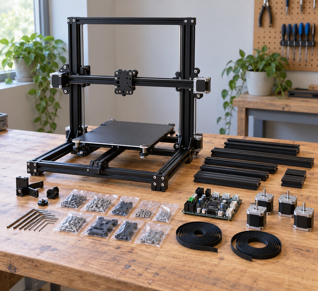
Yes, you can build a 3D printer from a kit at home. Most first builds take 8 to 15 hours spread over two or three sessions, and every consumer kit is an FDM machine: you bolt together the frame, fit rails, motors and belts, wire the controller board, flash the firmware, then calibrate until the first layer sticks.
This guide walks through how to build a 3D printer from a kit in nine stages, with a check at the end of each one so you know the stage worked before you move on. Assembly is mechanical work with a wiring and firmware tail. If you have never flashed a board or set a Z-offset, budget the extra evening.
Parts, fastener sizes, connectors and firmware steps change between models and revisions, so treat the manual shipped with your exact kit as the authority. Where this guide describes a general method, the manual tells you the specifics.
Updated for October 2026.
Table of Contents
- What You Need
- Step-by-Step: How to Build a 3D Printer from a Kit
- 1. Check the Parts and Prepare the Workbench
- 2. Assemble the Frame and Base: How to Build a 3D Printer from a Kit Starts Here
- 3. Install Linear Motion Components
- 4. Mount the Motors, Belts, and Pulleys
- 5. Fit the Toolhead, Hot End, and Extruder
- 6. Install the Heated Bed and Leveling System
- 7. Connect the Electronics and Cables
- 8. Load Firmware and Complete Initial Calibration
- 9. Run a Safe Test Print and Inspect the Result
- Common Mistakes
- Frame or motion binds
- Crossed or loose belts
- Loose connectors and skipped endstops
- Reversed motors
- Unstable levelling and a first layer that will not stick
- Over-torqued plastic and cracked parts
- Overheating and electrical hazards
- Frequently Asked Questions
- How difficult is it to build a 3D printer from a kit?
- How long does it take to assemble a 3D printer kit?
- What tools do I need to build a 3D printer?
- Do I need to solder or program anything to assemble the printer?
- Can I build a 3D printer from a kit and then modify it?
- What should I check if the assembled printer will not move or print?
What You Need
A kit usually arrives with everything mechanical pre-cut: frame pieces, linear rails or smooth rods, NEMA 17 stepper motors, GT2 belts, idler pulleys, a heated bed, a hot end, an extruder, a controller board, a power supply and a bag of fasteners per assembly stage.
What it almost never includes is the tooling. These are the items experienced builders consistently buy separately before starting, not halfway through:
- Hex keys in the sizes the frame uses, usually 2 mm, 2.5 mm, 3 mm and 4 mm
- An electronics screwdriver with a magnetic bit holder, plus a spare 2.5 mm bit
- Diagonal cutters, wire strippers and small crimp connectors if the kit needs terminated wires
- Tweezers, both straight and angled, for routing loom and placing heat-shrink
- Isopropyl alcohol and lint-free wipes for cleaning rails, rods and finger oils off parts
- Bearing grease or a PTFE-lubricated oil for packing linear bearings
- A multimeter for continuity, resistance and polarity checks
- Cable ties, spiral wrap and sticky notes for labelling and strain relief
- A small parts organiser with separate compartments per fastener bag
- A feeler gauge set, and a square or machinist square for checking the frame
- Compressed air or a soft brush for clearing swarf from slots and crevices
Your workspace matters more than most guides admit. You need a flat surface with enough room for the full frame footprint, good light, and access from both sides so you can reach the back of the vertical axis. Mains power goes to one outlet, ideally the power supply first and the heated bed last on the daisy chain.
Gather the documents before you unbox: the printed manual, the bill of materials, the board wiring diagram, and the firmware configuration profile for your exact board revision. Builders report repeatedly that the online manual for their kit revision beats the paper booklet, because the booklet is often from an earlier run.
Before you start, decide what kind of machine you are actually building. Kits fall into three families, and picking the wrong one is the most common regret first-time builders report.
| Architecture | How it moves | Build difficulty | Best for a first build |
|---|---|---|---|
| Cartesian bedslinger | Each axis has one motor and one belt; the bed moves on Y only | Lowest | Yes. Fewest axes, easiest to level, cheapest to repair |
| Delta | Three towers pull a toolhead in a triangle | High | No. Needs expert firmware knowledge and precise effector geometry |
| CoreXY | Two motors coordinate both bed axes through belts | Medium to high | Only after a bedslinger. Fast and rigid, but the wiring and belt path are unforgiving |
Most experienced builders say the same thing: build a simple bedslinger first, then move up. A Voron or any CoreXY design is a rewarding second machine, not a first one.
Step-by-Step: How to Build a 3D Printer from a Kit
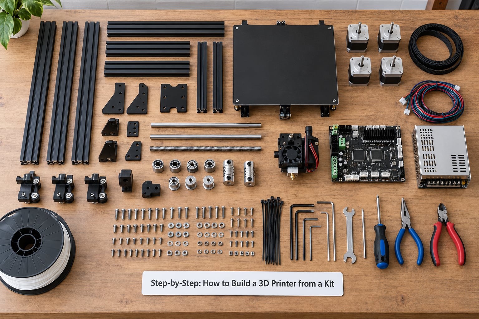
The table below is the whole build at a glance. Use it to plan your sessions rather than as a substitute for the manual.
| Stage | Task | Main tools | Typical time |
|---|---|---|---|
| 1 | Inventory parts and prepare the bench | Manual, organiser, marker pen | 30 to 60 minutes |
| 2 | Frame and base assembly | Hex keys, square | 1 to 2 hours |
| 3 | Linear rails and carriages | Hex keys, IPA, grease | 1 to 1.5 hours |
| 4 | Motors, pulleys and belts | Hex keys, 2 mm drive rod | 1 to 2 hours |
| 5 | Toolhead, hot end and extruder | Hex keys, tweezers | 1.5 to 2.5 hours |
| 6 | Heated bed and levelling system | Hex keys, feeler gauge | 45 to 90 minutes |
| 7 | Electronics and cable routing | Screwdriver, multimeter, cutters | 1.5 to 3 hours |
| 8 | Firmware and first calibration | Laptop, USB cable, printer software | 1.5 to 3 hours |
| 9 | Test print and inspection | Slicer, spatula, scraper | 1 hour plus print time |
1. Check the Parts and Prepare the Workbench
Lay out every bag and count it against the bill of materials before you tighten a single fastener. Kits pack by stage, so keep the bags in order and do not mix them.
Check the printed plastic parts for cracks, burrs and damaged screw bosses. Clear any support material from the holes by twisting a 3 mm drill bit in them by hand. It takes a minute per part and prevents stripped threads later.
Sort fasteners by type into compartments and label them. Experienced builders photograph each bag before opening it, which turns the last stage into a lookup instead of a hunt.
Keep every mains-powered component unplugged until the wiring stage is finished and inspected. That is the single safety habit that matters most here.
Check before moving on: every bill-of-materials line is accounted for, every fastener type has a home, and no powered part is within reach of your hands.
2. Assemble the Frame and Base: How to Build a 3D Printer from a Kit Starts Here
Build the base sections flat on the bench first, then bring the uprights in. Follow the manual’s orientation exactly, because the extrusion handedness differs between sides on most kits and a swapped upright will not accept the later brackets.
Tighten in a star pattern, moving around the joint rather than working one corner to completion, and work diametrically opposite bolts in alternating passes. Aerospace technicians working on plastic assemblies describe the target as feel the bite, then a quarter turn more.
Do not use an electric screwdriver on printed frames. The torque is unpredictable and printed bosses crack. If a part does crack, glue it back with cyanoacrylate, let it cure fully, and fit a washer on the far side to spread the load.
Check squareness by pressing the frame gently on all four sides. If it racks or twists, a corner is under- or over-tightened. Loosen the whole joint and bring it up evenly.
Check before moving on: the frame sits flat on the bench and does not rock, and pushing any face leaves no perceptible movement at the joints.
3. Install Linear Motion Components
Degrease smooth rods and linear rails with IPA and a lint-free wipe before fitting anything. Finger oils are the main cause of premature wear on a rail, and it takes thirty seconds now to avoid a stutter in six months.
Take the manual’s measurements for the mount positions. Slide each carriage on by hand and confirm it runs the full axis length with even, quiet resistance. If a carriage binds at one end, back the mount off and re-shim rather than forcing it.
If your kit uses LM8UU linear bearings, pack each one with a thin film of grease by hand. Roll the bearing between your palms and work the grease in, rotating the cage as you go. Over-packing is as bad as no packing, so stop when the grease stops spreading.
Support blocks set the axis height and the rail angle. Fit them with the specified shims and check the axis is level across its width before tightening anything permanently.
Check before moving on: every carriage travels the full travel by hand with the same force at both ends and no scraping.
4. Mount the Motors, Belts, and Pulleys
Set each motor’s pulley at the specified distance from the frame face. A few millimetres of error here shows up later as uneven belt teeth or a pulley that runs out of alignment, so measure rather than eyeball.
Route each GT2 belt and tension it using the kit’s idler slots. For a measurable check, pluck the belt like a guitar string and read the frequency with a phone tuner app; experienced builders report roughly 90 Hz as the working zone for common GT2 setups on a bedslinger.
Belt teeth must mesh fully on both sides of the pulley. A belt running slightly off the edge under tension will round teeth and produce layer shifts weeks later.
If the kit includes cable chains, attach them now with the correct slack. Too tight and the moving axis drags the loom; too loose and it snags at the end of travel.
Check before moving on: each axis moves by hand along its full range with no binding, no rubbing, and no perceptible backlash.
5. Fit the Toolhead, Hot End, and Extruder
Assemble the extruder and hot end on the bench before attaching them to the carriage. Doing the fiddly work flat, with the toolhead supported, is faster and avoids dropping a hot-end assembly across the frame.
Route the PTFE or PTFE-lined Bowden tube along the path the manual specifies and secure it at both ends with the correct collet or clamp. Tube that is too long or kinked causes filament feed problems that look like an extruder fault.
Confirm the nozzle is firmly seated and level when the carriage sits on its blocks. A nozzle backed too far out will melt the inside of the heat break before it ever reaches the bed.
Fit the part cooling fan and any ducting, and check that nothing spins near the belt path. Then move the carriage by hand again and confirm nothing catches.
Check before moving on: the carriage slides smoothly through its full range, the nozzle points straight down at every Z height, and the fan spins freely.
6. Install the Heated Bed and Leveling System
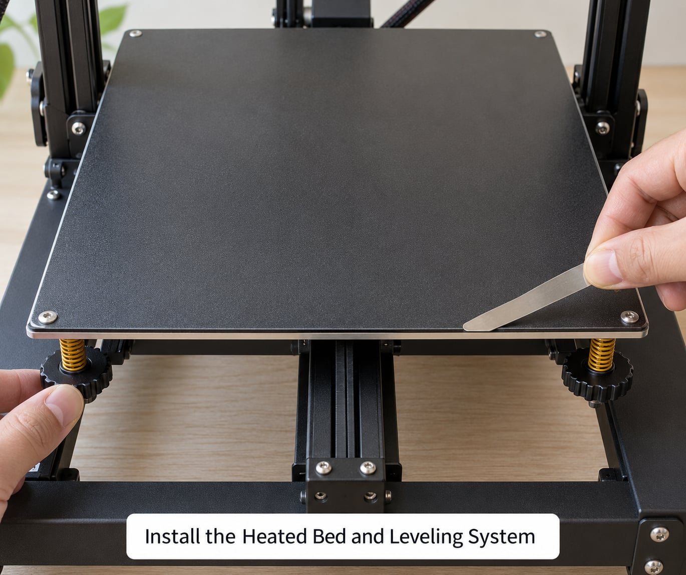
Three different operations get called levelling, and mixing them up wastes hours. Tramming means the bed surface is parallel to the printer’s frame. Levelling sets the gap at all four corners. Mesh bed levelling builds a tilt compensation map, and auto bed levelling with a BLTouch or CR Touch probe does both automatically.
Fit the bed surface the manual specifies, and route the heater and thermistor leads so they cannot be pinched by bed movement. Strain on a cold solder joint there is the most common cause of a bed that stops reading temperature weeks later.
Level the cold bed first with a feeler gauge at all four corners plus the centre. Most kits use springs or a knob at each corner; tighten the springs evenly rather than leaning on one corner.
Check the cable path again with the bed at both extremes of its travel. Nothing should stretch, drag or sit against the heated surface.
Check before moving on: the feeler gauge drags with equal light resistance at four corners and centre, and the bed heater cable moves freely.
7. Connect the Electronics and Cables
With mains power switched off and unplugged, mount the power supply and controller board, then work through the wiring diagram one connector at a time. Motors, drivers, thermistors, heaters, fans, endstops and the bed probe each have a defined position, and the diagram is the map.
Check heater polarity. Both ends of a heater cartridge and a heated bed are non-polar in function, but controllers and firmwares frequently assume a defined orientation, so fit them as the diagram shows and confirm with a multimeter before powering on.
Never bridge a fuse, defeat the bed probe, or work on the board with mains power connected. If a fuse blows, find the cause; a replaced fuse is not a repair.
Use cable ties and spiral wrap to dress the loom, and leave service loops at both board ends so you can pull the board out later without unplugging nine connectors.
With everything connected, do a continuity and resistance check on the heaters and thermistors before the first power-up. Values that read as a dead short need investigation now.
Check before moving on: every connector from the diagram is present and seated, no bare copper is visible, and the board’s grounds are connected per the diagram.
8. Load Firmware and Complete Initial Calibration
Use the firmware the printer’s manufacturer supports. Marlin 2.1.x with a PlatformIO configuration is the standard for 32-bit boards; Klipper is a strong alternative if you want network control and later upgrades. Ignore guidance built around 8-bit Arduino and RAMPS boards for new builds, and ignore instructions to install Python 2.7 or download firmware from old repository links.
Flash over USB serial with the board unpowered, then power the printer and connect with a host program such as PrusaSlicer, OrcaSlicer, Cura or OctoPrint. Confirm each motor turns the correct axis in the correct direction and reverse the flag in the configuration if not.
Set steps per millimetre from the manual’s values, then verify with a commanded 100 mm move and a ruler. An axis that stops short or overshoots needs its steps-per-mm corrected here, not later.
Establish the endstops or sensors. Home all axes and confirm the Z endstop triggers slightly below the nozzle’s resting height, not above the bed surface.
Then re-level the bed and run the manual’s cold axis check, moving each axis through its full range while you listen for binding or missed steps.
Check before moving on: every axis homes, moves 100 mm accurately, reverses without binding, and the nozzle parks just above the bed with the endstop flag off.
9. Run a Safe Test Print and Inspect the Result
Start with the manufacturer’s recommended first object, or a small layer-height test. It is not the most impressive thing to print, but it exposes layer consistency, first-layer adhesion and flow problems at a fraction of the filament of a real part.
Stay with the printer for the first heat-up. Watch for the nozzle clearing the bed, listen for the fan, and keep a metal spatula and a pair of pliers within reach in case a part sticks mid-bed.
When it finishes, let the bed cool before removing anything. Warm plastic pulls away from the build surface unpredictably and can tear the surface sheet on thin or magnetic beds.
Inspect the result against a simple list: is the first layer a single solid line with no gaps, are layer heights even top to bottom, are corners square, and are there any blobs or stringing. Note every fault in writing so you can fix them one at a time.
Check before moving on: the test object released cleanly, the first layer was continuous, and every fault you noted has a cause you can name.
Common Mistakes
Almost every failed first build traces back to one of these. Each has a fix you can verify without taking the printer apart again.
Frame or motion binds
Symptom: the axis stutters, or motors get hot and lose steps during a move.
Cause: a joint is not square, a carriage is running against its mount, or the motor pulley is not parallel to the idler.
Fix: loosen the joint and retighten it in a star pattern, then re-shim or adjust the support block until the carriage moves freely by hand. Verify by moving the axis full range under power and feeling for a torque increase anywhere.
Crossed or loose belts
Symptom: random layer shifts, or the axis moves the wrong way.
Cause: a belt routed across itself instead of around the pulley, or tension left at whatever the screws happened to feel like.
Fix: retrace the belt path from the motor to the idler, confirm teeth mesh on both faces of every pulley, and set tension with the Hz method described in stage 4. Verify by commanding a long move and confirming the return trip is repeatable.
Loose connectors and skipped endstops
Symptom: motors jog but do not move, or a heater reports an open circuit.
Cause: a connector not fully seated, a crimp that did not take, or an endstop flag set for normally-closed wiring when the kit uses normally-open.
Fix: reseat every connector with the board unpowered, inspect crimps for exposed copper, and confirm the endstop switch state matches the configuration. Verify with a multimeter on continuity, then watch the endstop flag toggle as you press each switch by hand.
Reversed motors
Symptom: the bed or axis moves in the opposite direction to the manual.
Cause: motor direction flags not set for this kit’s cable routing.
Fix: invert the direction flag for that stepper in the firmware configuration and re-flash, or swap the two motor wires at the board. Verify with a 10 mm manual move before running anything automatic.
Unstable levelling and a first layer that will not stick
Symptom: the corners of the first layer separate, the print lifts, or the layer is squashed into a ridge.
Cause: the bed is not parallel to the frame, the Z-offset is wrong, or the bed and nozzle are dirty.
Fix: tram the bed cold with a feeler gauge, clean both surfaces with IPA, then set Z-offset again and print a single-layer test. If you have a probe fitted, remember it measures nozzle-to-bed at probe points, not whole-bed flatness, so tramming still comes first.
Over-torqued plastic and cracked parts
Symptom: a printed boss splits, a screw head strips, or the joint stays loose after tightening.
Cause: electric-driver torque on plastic, or thread friction eating the turn before the joint actually clamps.
Fix: break the thread by running the fastener in and out a few times before the final tighten, then take the joint to firm resistance plus a quarter turn. Verify with a square on the frame and a gentle push test.
Overheating and electrical hazards
Symptom: a scorched smell, a connector that is discoloured, or a bed that runs away in temperature.
Cause: loose high-current connections, blocked vents, or a heater wired with no thermal safety margin.
Fix: power down at the wall, undo the connector, re-terminate it properly and reseat it, and confirm the heater current reading in firmware looks sane. Never bypass a fuse or ground to make a fault disappear.
Pre-power inspection checklist: square frame with no rock, every carriage free by hand, belts toothed correctly and tensioned, connectors seated with no exposed copper, heater and thermistor resistances verified on a meter, fuses intact and grounding as the diagram specifies.
Frequently Asked Questions
How difficult is it to build a 3D printer from a kit?
Moderately hard for a first-timer, mostly because it combines mechanical assembly, wiring and firmware rather than any single difficult skill. The frame work is straightforward if you are patient. The electronics and firmware stages are where most people stall, so read the manual for your exact board revision before you buy parts.
How long does it take to assemble a 3D printer kit?
Expect 8 to 15 hours for a first build, which usually means two or three sessions rather than one long day. Mechanical assembly takes the bulk of that time, and wiring and firmware configuration add a few hours on top. Builders who read the full assembly section before starting finish faster because they stop and search for a part less often.
What tools do I need to build a 3D printer?
You need hex keys in the sizes the frame uses, an electronics screwdriver, diagonal cutters, tweezers, isopropyl alcohol, bearing grease, a multimeter, a feeler gauge set, a square, cable ties and a small parts organiser. Most kits supply none of these, so buy them before you unbox anything rather than discovering the gap mid-build.
Do I need to solder or program anything to assemble the printer?
It depends on the kit. Many boards arrive with drivers, motors and headers pre-installed, so no soldering is needed and you only configure firmware through a menu or a configuration file. Kits that supply loose stepper drivers and bare wires expect you to solder or crimp them yourself. Check the parts list for your revision first.
Can I build a 3D printer from a kit and then modify it?
That is one of the best reasons to build a kit in the first place. Motors, drivers, firmware, hot end, bed and probes are all standard parts you can swap later, and you understand the wiring well enough to change it. Follow the manual for the base build, then change one thing at a time so you always know which change fixed or broke something.
What should I check if the assembled printer will not move or print?
Start with the endstops. Home the axes by hand and confirm each switch toggles when pressed, then check that the motor direction flags match your cable routing. If a motor hums without turning, reseat its connector and confirm the driver module is seated. Bring the exact printer manual to the fault, because wiring differs between board revisions.
Start on day one with the parts inventory, not the frame. Read the full assembly section of your manual, count every bag against the bill of materials, and buy the tool list above before you open the first box. A build that starts organised finishes organised, and a finished printer that moves, homes and prints a clean test layer is the real finish line.