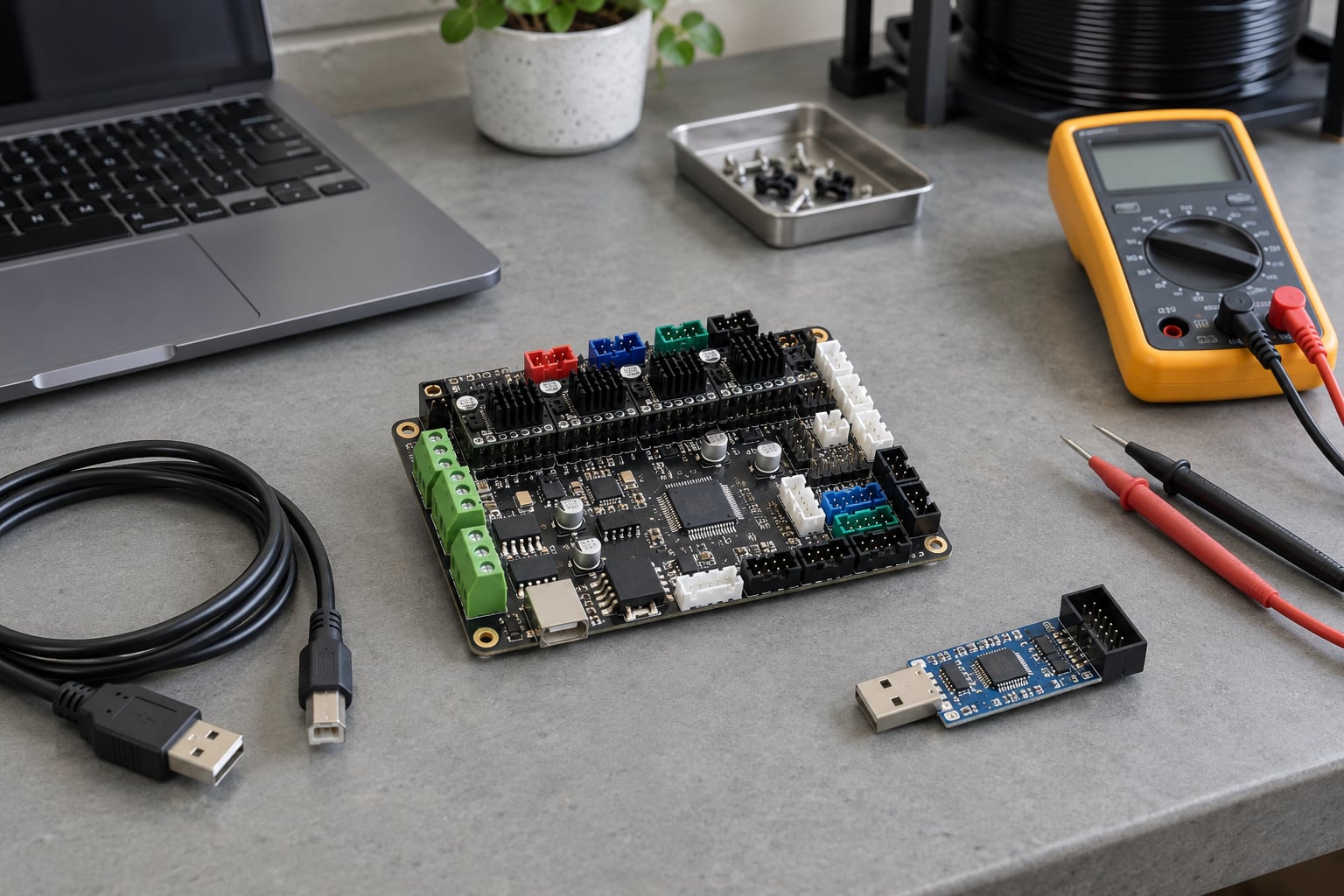
To flash firmware on a 3D printer board, you connect the mainboard to your computer over USB, load Marlin or a precompiled .hex file into the Arduino IDE, pick the correct board and serial port, then compile and upload. The board’s bootloader accepts the upload and writes it into flash memory. With no bootloader, you go through the ICSP header with a USBtinyISP instead. Budget 30 to 60 minutes the first time. This guide is current for Arduino IDE 2.x and Marlin 2.1.x and 2.2.x as of 2026.
Most people only need Method 1 or Method 2 below. Method 3 exists for the boards that refuse a normal USB upload, and it is the one people regret not reading before they panic about a dead printer.
Table of Contents
- What You Need to Flash Firmware on a 3D Printer Board
- Step-by-Step
- Identify the board and its supported firmware
- Back up the current firmware and settings
- Select the exact firmware build and flashing tool
- Put the board into the correct firmware-update mode
- How to flash firmware on a 3D printer board and verify the result
- Flash a precompiled .hex without compiling
- Flash a board with no bootloader using ICSP
- Common mistakes and the error decoder
- Frequently Asked Questions
- Can flashing firmware brick a 3D printer board?
- What should I do if the computer does not detect the board in bootloader mode?
- Should I restore EEPROM settings after updating firmware?
- Can I install an older firmware version on a 3D printer board?
- Do I need a separate programmer to flash the board?
- How do I know the firmware was installed successfully?
- The Safe Order of Operations
What You Need to Flash Firmware on a 3D Printer Board
Gather all of this before you open the printer. Most failed flashes come down to a missing driver or a board selection nobody checked first, and both take about a minute to rule out.
- The board’s own documentation. The mainboard model number printed on the PCB, plus the firmware page your printer’s maker publishes. This is the single most important item, because it decides which firmware build you are allowed to use.
- A stable computer and a known-good USB cable. Charge the laptop, or use a desktop on a grounded supply. Use the data cable that came with the board or a short shielded one, because charge-only cables and long thin ones cause phantom sync errors.
- A USB-serial driver. Most 8-bit boards use a CH340 or CP2102 chip. On Windows the CH340 driver is the one people forget, and on macOS the system usually has it already.
- The flashing software. Arduino IDE 2.x for source builds, or the update tool built into your slicer for a hex file, or PlatformIO if your board’s maker ships one.
- The firmware itself. Either the Marlin source tree or a precompiled .hex from your printer’s maker. Pick one path before you start.
- A record of your current firmware and settings. Export any EEPROM or configuration the machine offers before you overwrite anything.
- Recovery access. A known-good USB port, and for 32-bit boards a working SD card. A printed or photographed note of your current motor direction and steps-per-mm values is worth more than you think.
- A programmer, only for Method 3. A USBtinyISP or an AVR-ISP, plus the ICSP ribbon cable or dupont leads.
- Patience for one full power cycle. Some boards take 30 to 45 seconds to finish booting into the bootloader before a PC sees them.
Two hardware families show up constantly. The 8-bit Creality board and the older Arduino Mega-based boards take the standard Arduino route, while the 32-bit SKR, Duet and Octopus boards are usually flashed from an SD card or over the air with a dedicated web interface instead.
| Mainboard | Select this in Arduino IDE | Processor | Normal route |
|---|---|---|---|
| RAMPS 1.4 | Arduino Mega 2560 | ATmega2560 | USB upload |
| RAMBo | Arduino Mega 2560 | ATmega2560 | USB upload |
| Creality V4.2.2 silent board | Arduino Mega 2560 | ATmega2560 | USB upload or hex via slicer |
| Creality V4.2.7 ST board | Arduino Mega 2560 | STM32F103RE | SD card or hex via slicer |
| SKR Mini E3 v2 / v3 | Not in the IDE | STM32F103RE | SD card or over the air |
| Duet 2 / Duet 3 | Not in the IDE | ARM Cortex-M4 | Duet web interface or USB |
| Octopus (BTT) 32-bit | Not in the IDE | STM32F407VE | SD card |
Windows names the port COM3 or COM4; macOS shows a long path like /dev/tty.usbserial-0001 in the IDE’s port dropdown. If the port list is empty on either system, the driver is missing or the cable is charge-only, and nothing else you try will work until that is fixed.
Step-by-Step
Three questions decide your route. If the computer already sees the board as a serial port when it is plugged in, start with Method 1 or Method 2. If the board has never appeared on your computer, or you have already tried the normal upload several times, skip to Method 3. If your board is 32-bit, use the SD card or web interface route instead of any of these.
Identify the board and its supported firmware
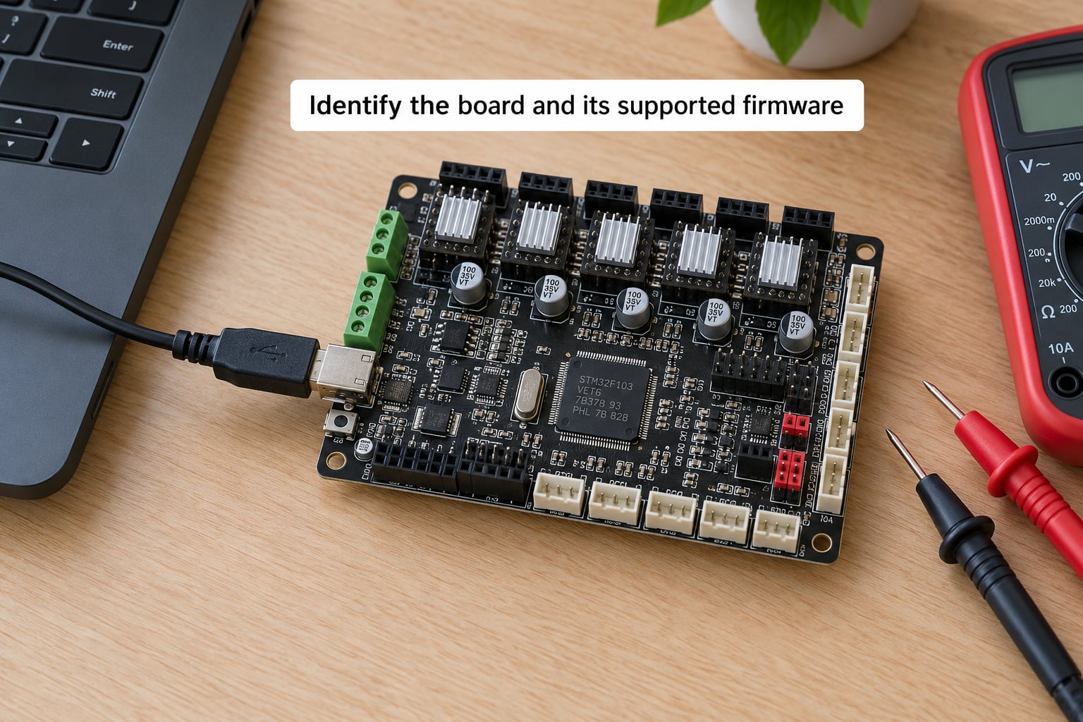
The board model is silkscreened on the PCB, usually near a corner or next to the USB port. Read it exactly, including the revision, because V4.2.2 and V4.2.7 boards look nearly identical and take completely different firmware.
This is where people get burned. Users repeatedly flash V4.2.7 firmware onto a V4.2.2 silent board after buying a replacement mainboard, and the machine either refuses to boot or reports a mismatched board. The 4.2.2 board runs ATmega2560 firmware and the 4.2.7 runs STM32 firmware, so the mismatch is physical, not a preference.
Note three things before you download anything: the processor or MCU marking, the flash size printed in the datasheet for that chip, and whether your printer’s maker publishes a preconfigured firmware for your exact model. Makers publish those builds for a reason. Use them when they exist, then move to source builds only when you need a feature they leave out.
Back up the current firmware and settings
Some machines expose a firmware export, an EEPROM dump, or a settings save on the LCD menu or in their web interface. If yours does, run it now and store the file somewhere outside the printer’s SD card, which is about to get overwritten.
Older Creality boards and many DIY machines have no export function at all. In that case write down what you need to rebuild by hand: axis steps per millimetre, bed size, PID values you have tuned, probe offsets, and which endstops are inverted. A phone photo of your Configuration.h settings is enough.
Also record what firmware is installed right now, so you can prove the later flash worked and, if it did not, know what to roll back to. Sending M115 from your host software returns a reply line with the firmware name and version, and many printers show the same string on an About or Info screen.
M115
FIRMWARE_NAME:Marlin 2.1.x (Github) SOURCE_CODE_URL:https://github.com/MarlinFirmware/Marlin PROTOCOL_VERSION:1.0 MACHINE_TYPE:Ender-3 EXTRUDER_COUNT:1 UUID:cede2a2f-41a2-4746-9b12-c55c62f367ff
Cap:EEPROM:1
Cap:AUTOREPORT_TEMP:1
Cap:EMERGENCY_PARSER:1
Cap:PROBE_OFFSET:1
Select the exact firmware build and flashing tool
Read the release notes for the firmware you picked, and check the hardware revision notes if your board is a Creality V4.2.x. Release notes are where the maintainers state which boards changed and which features moved. Skipping them is how you end up with a build that assumes hardware you do not have.
For a Marlin source build, download the release archive, extract the whole folder, and do not open the zip in place. People open a .zip and get a cascade of confusing compile errors that has nothing to do with their board.
Inside the extracted folder, copy the config for your machine from the examples directory into the firmware folder itself, so it overwrites the default. Then open Marlin.ino, not any single file. The IDE needs the whole folder.
Most makers change about six lines in Configuration.h and Configuration_adv.h:
#define BAUDRATE 115200
#define MOTHERBOARD BOARD_CREALITY_V4
#define TEMP_SENSOR_0 1
#define INVERT_X_DIR false
#define DEFAULT_AXIS_STEPS_PER_UNIT { 80.0, 80.0, 400.0, 500.0 }
#define HEATER_0_MAXTEMP 260
Use the word form for inch marks inside any value you type, and keep each line intact. A missing comma in the steps-per-unit array is a compile error that names the array rather than the cause, and it catches almost everybody once.
Put the board into the correct firmware-update mode
Power the printer off, unplug it from the wall, and disconnect the USB cable before changing anything. Removing mains power rather than just switching off matters on boards that stay partly live from the power supply.
Many boards expose two programming headers: a USB port and a six-pin ICSP header. For a normal upload you use the USB port and the board’s bootloader listens automatically. For a board with no bootloader, or a recovery flash, you use the ICSP header.
Some boards need a manual step. A jumper or button labeled BOOT, BFB, or ISP puts the processor into bootloader mode at power-on. Press and hold the button, apply power, and keep holding for a few seconds while the computer enumerates USB devices, then release. Boards with this button are usually documented with a jump sequence that tells you exactly which seconds to hold.
You know you are in bootloader mode when the computer reports a new device appearing, or when an AVR programmer reports an ATmega2560 signature. On the Creality silent board and most ATmega2560 boards there is no button to press, which is why the normal USB upload simply works there.
| Method | Hardware needed | Difficulty | Can you repeat it later |
|---|---|---|---|
| Marlin from source in Arduino IDE | USB cable, IDE, board chosen correctly | Medium | Yes, as often as you like |
| Precompiled .hex through a slicer or host | USB cable, matching firmware file | Low | Yes |
| SD card or over the air on 32-bit boards | MicroSD card, or network access | Low | Yes |
| ICSP with a USBtinyISP | Programmer, 6-wire cable, board access | High | Yes, but slower |
| ICSP with a second Arduino as ISP | Spare Arduino, jumper wires | High | Yes |
How to flash firmware on a 3D printer board and verify the result
This is the main path. With Arduino IDE 2.x open and Marlin loaded from source, work through the settings once before you upload.
- Open the Marlin folder and double-click Marlin.ino so the IDE loads the whole sketch.
- In the sidebar or Tools menu, add the board package your board type needs. IDE 2.x handles this in the Boards Manager rather than through extra board URLs, which is where most of the older guides go stale.
- Select the board type and processor. For RAMPS and Creality V4.2.2 that means Arduino Mega 2560 with ATmega2560.
- Install any libraries the compile asks for, usually U8glib and a display library for an LCD.
- Plug in the USB cable and pick the serial port from the Tools menu.
- Press Verify to compile only. Fix every error here. Nothing reaches the board in this step.
- Press Upload to compile and send in one action.
- Watch the console for the write finishing, then reset the printer with the power cycle.
- Power the printer on and let it run its start-up screen and homing routine.
- Run Initialize EEPROM from the LCD menu, or send M501 over your host software.
Step 10 is not optional when you changed configuration. The old EEPROM still holds the previous board’s step values and probe settings, and Marlin reads it in preference to your new compile. Skip it and the printer homes into the bed with the old numbers, which is the single most common post-flash complaint. The phone photo of steps-per-mm you took earlier is what makes this step fast.
Verify in three ways. The LCD should boot and home without a stall or a stepper grinding against a limit. Sending M115 should return a new firmware name and version. Then print a small test part, a 20 mm cube, and confirm the bed and nozzle hold temperature and the first layers stick.
If the printer only shows the temperature screens and the controls do nothing, you have flashed but not initialized. Do the M501 first before you start swapping firmware.
Flash a precompiled .hex without compiling
You do not need the IDE if your printer’s maker publishes a matching .hex. Both major host programs can push one to the board for you.
In Cura, open Manage printers, click the firmware icon next to your machine, choose Update Firmware, then Upload custom Firmware and point it at the .hex. In OctoPrint, open Firmware, choose Flash from file, pick the .hex and select the correct serial port and baud rate before you flash.
Set the baud rate to match the firmware. Most 8-bit boards use 115200, many newer boards use 250000, and a mismatch gives you a board that appears to flash and then goes quiet.
On 32-bit boards the same idea moves to an SD card. Copy the .bin to a FAT32-formatted card, name it exactly what the board expects, insert it with the printer powered on, and the board updates on its next restart. Prusa-style machines take this further with an over-the-air updater that pushes firmware over the network.
If an SD card update refuses to run, the cause is usually not software. Reformat the card twice, then try a different card, then re-download the file from the vendor site. Check the board’s connector too, since a cable seated badly under a plastic cover produces no error message at all.
Flash a board with no bootloader using ICSP
No bootloader means the processor has no program listening for an upload, so the normal USB route cannot work no matter how many times you try it. ICSP talks to the chip directly and does not need one.
The ICSP header is a 2 by 3 pin row. Wire your programmer to it exactly as follows, with the ribbon cable’s red pin marking pin 1.
| Pin | Signal | Goes to |
|---|---|---|
| 1 | MISO | Programmer MISO |
| 2 | VCC | 5 V reference |
| 3 | SCK | Programmer SCK or CLK |
| 4 | MOSI | Programmer MOSI |
| 5 | RESET | Programmer RESET |
| 6 | GND | Programmer GND |
Check this wiring twice against the board’s silkscreen before you power anything up. Swapped MOSI and MISO produce a verification error rather than damage, but a VCC-to-GND slip is a dead programmer.
One warning matters more than the rest: on a USBtinyISP, remove the power-supply jumper. With that jumper fitted while the printer’s power supply is on, current can back-feed into your computer’s USB port. Power the board from the printer’s own supply, or from the programmer with the board otherwise unpowered, and never both.
Then choose the programmer in the IDE’s Tools menu, pick the right chip, set the right clock speed for your programmer, and you have two choices. Upload using Programmer sends firmware only and leaves the bootloader situation as it was. Burn Bootloader writes a bootloader into the chip first, which is what you want if you plan to use normal USB uploads from then on.
Order matters. If you burn a bootloader and then immediately upload using Programmer, the second write can overwrite the bootloader you just installed. After a Burn Bootloader step, disconnect and reconnect over plain USB for your actual firmware upload.
Common mistakes and the error decoder
Match your console output to the string below. These are the errors that fill the forums, quoted exactly as they appear.
| Error string | What it means | Fix |
|---|---|---|
| avrdude: stk500_getsync() attempt 10 of 10 not in sync: resp=0x0 | The board’s bootloader never answered. The most repeated error on every printer forum. | Reset the board during the upload, press the boot or reset button at the moment the IDE says it is writing, or use ICSP. |
| avrdude: verification error, first mismatch at byte 0x0100 | The write completed but the read-back differs, so flash or supply is unstable. | Try a different USB cable and port, and stop using a USB hub. |
| avrdude: programmer is not responding | The programmer has no connection to the chip. | Check MISO and MOSI orientation, confirm pin 1, and lower the clock speed. |
| avrdude: error: no programmer connected | The IDE has a programmer selected but nothing is plugged in. | Plug the programmer in, or switch the upload method back to the serial port. |
| Error during upload: received from MCU: FFFFFFFF | Board power is missing or the cable is charge-only. | Power the board from its own supply and swap the data cable. |
| error: typedef-name ‘fpos_t’ after struct | Old firmware written for Arduino IDE 1.6 or earlier. | Update the firmware source, or compile it in an older IDE as a last resort. |
| fatal error: U8glib.h: No such file or directory | A required library is missing. | Install the library the compile message names and compile again. |
| Board at COMx is not a genuine Arduino board | The board type does not match what you selected. | Match the IDE’s board and processor to your actual hardware. |
| Blank LCD, no response to M115 after a flash | Usually EEPROM not initialized, or a config that disables the display. | Send M501, then power cycle. If it stays blank, use ICSP. |
| Printer homes hard into the bed after flashing | Old EEPROM values are still in use. | Initialize EEPROM and re-home before anything else. |
Two habits prevent most of the above. Save your current EEPROM and steps-per-mm numbers before any flash, and never upload on the first try after opening the IDE with an unfamiliar cable. Do one harmless compile and upload cycle first while the board is still responsive.
If you are deciding between Marlin and Klipper, the deciding factor is config friction. Marlin is where most people start, and Klipper is the common upgrade path, because Klipper config lives in text files you edit without re-flashing anything. Marlin needs a recompile for every change, which is exactly the tax that pushes people across. Klipper is free and open source, and it runs on the same 8-bit and 32-bit boards with a Raspberry Pi or similar host handling the work.
Frequently Asked Questions
Can flashing firmware brick a 3D printer board?
Not permanently, in almost every case. Flash memory survives a failed upload, so a board with a bootloader can always be reflashed over USB, and one without a bootloader can be recovered through the ICSP header with a USBtinyISP. The genuinely hard-to-recover failures are hardware ones, such as reversing power to the board or leaving a programmer’s power jumper fitted. Back up your EEPROM, keep your original firmware file, and treat the risk as low.
What should I do if the computer does not detect the board in bootloader mode?
Check the four things in order: a data cable rather than a charge-only one, the USB-serial driver installed, the board actually powered, and the correct boot or reset button held at the moment power is applied. Then wait 45 seconds, since some boards enumerate slowly. If the port still never appears, stop retrying the USB route and use ICSP, which does not depend on the bootloader being present.
Should I restore EEPROM settings after updating firmware?
No. Initialize EEPROM instead, using M501 or the LCD menu. EEPROM holds the values your previous firmware compiled in, and loading it into new firmware can set wrong steps-per-mm or a bad probe offset. After initializing, re-home all axes and re-level the bed. Only restore an EEPROM backup when you are deliberately rolling back to matching firmware and need your tuned PID values back.
Can I install an older firmware version on a 3D printer board?
Yes, and it is a normal recovery move when a new build behaves badly. Install the older version the same way you installed the new one, then initialize EEPROM to match, and expect your steps-per-millimetre and PID values to reset to that version’s defaults. Keep the newest working .hex file on your computer so you can roll forward again without re-downloading anything.
Do I need a separate programmer to flash the board?
Only if your board has no bootloader, refuses USB uploads, or you want to install a bootloader. A USBtinyISP is the common choice, and a spare Arduino running the ArduinoISP sketch works as a free alternative with jumper wires. If your board appears on your computer as a serial port, you do not need any programmer at all and can use the IDE, your slicer, or an SD card.
How do I know the firmware was installed successfully?
Three checks. Send M115 and confirm the returned firmware name and version differ from what you had before. Power cycle and watch the printer run its boot screen and home without grinding into a limit. Then print a small test cube and confirm stable bed and nozzle temperatures. If the LCD stays blank but heaters respond, the firmware is in and only the EEPROM needs initializing.
The Safe Order of Operations
Start by reading the exact board revision printed on your mainboard, not the model name of the printer. Use the firmware your maker publishes for that board unless you have a reason not to, keep a copy of what is installed today, and flash only a build that matches the hardware.
After the upload, initialize EEPROM before anything else, then re-home, re-level and print a small test part. Watch bed and nozzle temperatures hold steady through a full job. Do all of that and a firmware update on a 3D printer board is about as risky as changing a setting in a menu, which is exactly what it is.