Installing a BLTouch auto bed leveling probe takes about an hour on most printers, and none of it is complicated once you know the order: mount the probe on the hot end carriage, wire four or five leads to the control board, tell your firmware the probe has taken over the Z endstop, then set the offset between probe pin and nozzle. The physical work is easy. The part that trips people up is firmware, because the settings that work on one board do not carry over to another.
This guide works for any printer with room on the print head and a spare control pin on its board. It also spells out the exact commands to run when something misbehaves, because most “BLTouch failed” messages are a wiring or configuration problem rather than a dead sensor.
Table of Contents
- What You Need
- Check your printer’s documentation first
- Step-by-Step: How to Install a BLTouch Auto Bed Leveling Probe
- 1. Check Printer and BLTouch Compatibility
- 2. Mount the BLTouch Probe
- 3. Connect the Wiring
- 4. Install or Update the Firmware
- 5. Set Probe Offset and Endstop Behavior
- 6. Run a Manual Test
- 7. Calibrate the Bed and Save Settings
- Common Mistakes and Fixes
- Frequently Asked Questions
- Why is my BLTouch not working?
- How do I set the Z offset after installing a BLTouch?
- Do I still need to level my bed by hand after installing a BLTouch?
- Do I have to remove the Z endstop switch?
- How do I connect my 3D printer to my computer to flash firmware?
- Can I install a BLTouch on any 3D printer?
- Conclusion
What You Need
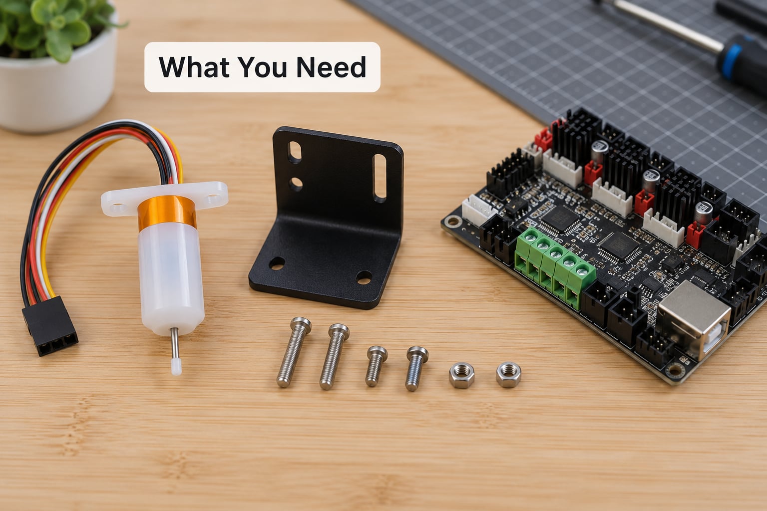
Gather everything before you open the printer. Reaching halfway through a step to find a missing hex key is how small scratches end up on a printer frame.
- The BLTouch probe itself, plus its mounting bracket and the supplied screws
- A matching control board or breakout board header, if your printer routes sensor wiring through one
- A Phillips screwdriver, a 2 mm hex key or driver bit, and small pliers
- A wire cutter or side cutters, and electrical tape or a cable tie for strain relief
- A computer with a USB cable and a serial driver installed for your board
- Your printer’s model number and mainboard version, printed or on the board silkscreen
- A spare copy of your current firmware, in case you need to roll the install back
- A sheet of plain paper and a flashlight for the Z offset step
Two safety notes before you start. Unplug the printer and flip the switch off the mains, not just the screen, because the heated bed and hotend draw power from a live supply even when idle. And decide where the probe will sit before tightening anything, because a mount that puts the pin within a few millimetres of the nozzle will crash into it the first time the head moves.
Check your printer’s documentation first
The single most useful document is your printer’s mainboard manual or schematic. It tells you the board version (4.2.2, 4.2.7, SKR Mini E3 v2.0, Octopus, and so on) and which headers are free. Board version matters because firmware builds are matched to it, and a mismatch is the most common reason a flash fails or the probe deploys when you expect it to stow.
Step-by-Step: How to Install a BLTouch Auto Bed Leveling Probe
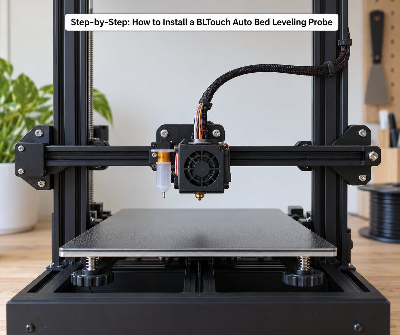
Work through these seven steps in order. Each one has a check you can run before moving on, and skipping the check is how you end up three steps deep with a problem whose cause was step two.
1. Check Printer and BLTouch Compatibility
Most Cartesian printers and many Presta-style machines can take a BLTouch, and many kits even include the printed bracket. What your printer must have is a control board with a free servo control pin, a free probe signal pin, and a 5V rail with an available ground.
Check the physical side too. The probe needs roughly 20 mm of clearance beside the nozzle, and the deploying pin must be able to reach the bed at all usable Z heights. Also confirm your firmware base: Marlin, RepRapFirmware and Klipper all support a BLTouch, but each exposes it in a different menu, and stock Creality firmware supports it only in specific board builds.
2. Mount the BLTouch Probe
Fix the bracket to the hot end carriage with the supplied screws, then attach the probe to the bracket so the pin deploys to the side of the nozzle, never in its path.
Two things to watch. Keep the pin roughly level with the nozzle tip when deployed, because a probe mounted several millimetres higher reads high and forces the nozzle down into the bed. And secure the mount firmly: a probe that moves under load changes its reading mid-mesh, and the printer will keep correcting for a fault that does not exist.
How you know it worked: power the printer on, home the axes with G28 from your terminal, then move the head over the bed. Watch the pin deploy and retract smoothly with nothing in its way.
3. Connect the Wiring
Route the cable down the frame, away from the bed, the belts and the moving gantry, and secure it every 100 mm or so with tape or a tie so tension never reaches the connector. Leave a loose service loop at both ends rather than a tight run.
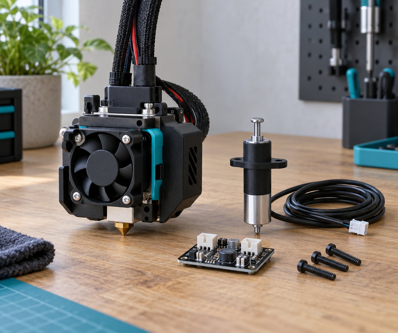
The standard BLTouch uses a five-lead servo-style connector. The usual colour convention is brown or orange for ground, red for +5V, white for the control signal, and black for the probe signal output. Clones on small breakout boards often use a four-pin JST header carrying +5V, ground, D11 for control and D12 for the probe signal.
Do not trust colour alone. The two red and brown leads in a servo-style plug are easy to swap, and reversed power will damage a probe. Read the silkscreen labels on your board, confirm 5V and ground against the schematic, and only then seat the connector.
How you know it worked: with the printer on, a multimeter on continuity confirms ground and 5V at the board end before you power up. If your board exposes a 5V and ground pair and a signal pair, those are the only conductors you need.
4. Install or Update the Firmware
The firmware must know the probe exists, which pin it is on, and that it has replaced the Z endstop. There are three common routes, and the right one depends on your board.
Stock Creality-style firmware. Your printer’s manufacturer or a well-maintained community site usually publishes a BLTouch-enabled .hex for each board version. Download the build that matches your exact board, then flash it over USB using the firmware flasher built into a recent PrusaSlicer or a dedicated flasher utility. Save a copy of the stock file first; you may want it back within ten minutes.
Marlin. In Configuration.h, define BLTOUCH_PIN to the probe signal pin, comment out Z_MIN_PIN so the firmware stops looking for a physical Z switch, set Z_MIN_ENDSTOP_INVERTING to false, and check the deploy and stow angles in Z_SERVO_ANGLES. Clone sensors in particular often need the angles swapped, because many clone firmwares treat the pin as active-high where the genuine unit is active-low. Recompile, flash over USB, and reset the stored settings afterward so the new configuration takes effect.
Klipper. Klipper has no compile step, which is why it is popular for this install. In printer.cfg, define a [bltouch] section with pin: for the probe signal and control_pin: pointing at a servo PWM pin on your board, then set probe_offset_left, probe_offset_right, probe_offset_front and probe_offset_back so the pin sits beside the nozzle. Point the Z endstop at the probe by setting [stepper_z] endstop_pin to the same signal. Restart Klipper and check the console output for a probe detected line.
How you know it worked: restart the printer. A correctly configured BLTouch runs its self-test on startup, the pin deploys, returns, and deploys a second time. If nothing moves, the control signal is on the wrong pin or the board is not receiving the firmware at all.
5. Set Probe Offset and Endstop Behavior
The Z endstop is the switch that tells the printer it has reached the bed. When a BLTouch is doing that job, the physical switch is no longer used, and you have two options: leave it connected but disabled in firmware, or unplug it. Leaving it plugged and disabled in firmware is the safer choice, because one setting change restores it.
The probe offset is the distance from the pin tip to the nozzle tip. Firmware measures the bed where the pin touches and assumes the nozzle is the same distance above it, so if the pin sits 2 mm below the nozzle, the offset is 2 mm. Get the sign backwards and you will chase the classic complaint of a printer that refuses to accept an offset below 0.00, which is really a firmware limit being hit by a value with the wrong sign.
How you know it worked: with the probe deployed and the bed below, G28 homes without the nozzle crashing into the bed, and the printer stops at a believable Z position rather than plunging.
6. Run a Manual Test
Before you trust the sensor, test it directly from a terminal such as Pronterface, OctoPrint or the printer’s own serial console.
M119reports the current state of the endstop and probe inputs, and tells you whether the trigger is invertedM280 P0 S10deploys the probe, andM280 P0 S90stows itG28homes all axes using the probe, andG29builds a mesh of probe points across the bed
Run M280 P0 S10 and M280 P0 S90 several times in a row. On a genuine unit the pin moves every time. If it deploys correctly but only retracts when you send the stow command explicitly, you are likely running clone behaviour and need the deploy and stow logic inverted.
Then place a sheet of paper on the bed, run G28, and check the gap between paper and nozzle at several points. It should be the same tight, dragging feel everywhere. Any variation means the probe is mounted loosely or angled.
7. Calibrate the Bed and Save Settings
Set the offset in firmware, not by hand. On most Marlin builds, move the nozzle to roughly 10 mm above the bed, deploy the probe with M280 P0 S10, then nudge the Z until a sheet of paper drags lightly under the nozzle. Read that value, undeploy, and enter it in the printer’s Z offset menu or as Z_PROBE_OFFSET in your configuration.
Direction is simple. If the nozzle is too close to the bed, you need a smaller value. If the first layer comes out as a gapped, blobby line, increase it. Store the setting with M500 on Marlin, or let Klipper’s probe offset wizard write it back to printer.cfg, and then reset the stored settings so the firmware reloads the saved value cleanly.
Finally, add the leveling commands to your slicer’s start G-code. G28 homes the axes, G29 builds the mesh, and M420 S1 restores the saved mesh on later prints. PrusaSlicer can do this for you when you select the printer as BLTouch-equipped in the printer settings.
How you know it worked: run a first-layer test print with a large footprint, like a 100 mm square skirt, and watch the line stay consistent from corner to corner.
Common Mistakes and Fixes
Almost every BLTouch problem shows up as one of these five symptoms, and all of them are diagnosable in a few minutes with the commands above.
The probe never moves. Nothing deploys at startup, so the control pin is wrong or unpowered. Confirm the control signal goes to a servo-capable pin and not to an endstop input, and check that the board is actually running BLTouch-enabled firmware. Swapping the control and probe signal wires will give you a probe that never triggers, which looks identical from the front.
Error 29, or “BLTouch failed” partway through a mesh. This is usually a loose connector or a cable being pinched by the moving gantry, not a broken probe. Add strain relief, then run the mesh again. A probe that fails only at one specific point usually means the bed surface is caught on a screw head or a warped sheet clips the pin.
The pin deploys when the firmware says stow, and the printer errors on every home. This is the classic clone symptom. The deploy and stow logic is inverted for that sensor, so swap the two angles in Z_SERVO_ANGLES, or invert the trigger logic in your Klipper config.
The probe triggers too early, so the nozzle lifts away from the bed. Your offset sign is inverted. Re-measure the pin-to-nozzle distance and enter it with the opposite sign; on Marlin this often means a value below 0.00, which some stock builds refuse to accept until you widen the allowed limit in the firmware.
The mesh looks fine but the first layer is still bad. Two usual causes. The G29 command is missing from your slicer start G-code, so the printer never actually probes, or your Z offset was set with the probe stowed rather than deployed. Also check that the bed is clamped down, because a lifted corner moves after the mesh is recorded.
One more worth knowing: a mount that is even slightly loose produces different readings between a cold machine and a warm one. Tighten it, run a mesh after a 20-minute soak, and if the two meshes disagree, it is your mount rather than your sensor.
Frequently Asked Questions
Why is my BLTouch not working?
In most cases the probe is wired to the wrong pins, or the firmware has the control signal and the probe signal swapped. Run M119, then M280 P0 S10 and M280 P0 S90. If the pin does not move at all, the control pin is wrong or the board is not running BLTouch-enabled firmware. If it deploys but only retracts when you command it, a clone needs its deploy and stow logic inverted.
How do I set the Z offset after installing a BLTouch?
Home the axes, deploy the probe with M280 P0 S10, and lower the nozzle until a sheet of paper drags lightly underneath. Read that gap, undeploy the probe, and enter the value in the printer Z offset menu or as Z_PROBE_OFFSET in your configuration. A value that needs to be smaller means the nozzle is too close. Store it with M500 on Marlin, or save the Klipper wizard result.
Do I still need to level my bed by hand after installing a BLTouch?
Only once. The probe maps the bed on every print, so the four corner knobs become a set-and-forget setting. Do a rough manual level first, and tighten every bed screw evenly, because auto leveling corrects height but cannot compensate for a bed that physically moves. Re-run G29 whenever you swap the bed surface, a spring, or a glass sheet.
Do I have to remove the Z endstop switch?
No. Disabling it in firmware is enough, and leaving it connected is safer because you can switch it back with one setting. Simply set Z_MIN_PIN to disabled in Marlin, or point the stepper_z endstop_pin at the BLTouch signal in Klipper. Physically unplugging the switch is optional and leaves you with no mechanical backup if the probe later fails.
How do I connect my 3D printer to my computer to flash firmware?
Use a USB data cable, not a charge-only cable, and plug it in with the printer powered on. Install the serial driver for your board so the COM port appears in your device manager. Open the firmware flasher built into a recent PrusaSlicer, select the board and the BLTouch-enabled file, select the right COM port and baud rate, and upload. Save your current firmware first so you can restore it.
Can I install a BLTouch on any 3D printer?
Any printer with a controllable print head, room beside the nozzle, and a control board with a free servo pin and a free probe signal can take one, which covers most Cartesian and Presta-style machines. Delta printers and some bed-slinger designs work too, but they use different probe mounting and mesh routines. Check whether a printed bracket already exists for your model before ordering a kit.
Conclusion
Start with the boring checks, because they prevent every expensive mistake. Confirm the probe will physically reach the bed, read the board silkscreen and schematic to identify your control and signal pins, and save a copy of your current firmware before flashing anything. Mount the bracket solidly, route the cable clear of the moving gantry, then configure the firmware and store your settings. Only after M119 and M280 P0 S10 and S90 behave correctly should you set the Z offset and print. Most installs that go wrong are diagnosed within ten minutes by those three commands.