Cracks on tall prints are a thermal-stress failure, not a bed-adhesion failure. So if you are searching for how to fix cracking on tall prints, skip the bed temperature: the part stays stuck to the plate while the accumulated layers split horizontally in the upper half. What actually helps is keeping the whole part warm, cutting cooling between layers, and removing stress risers from the model.
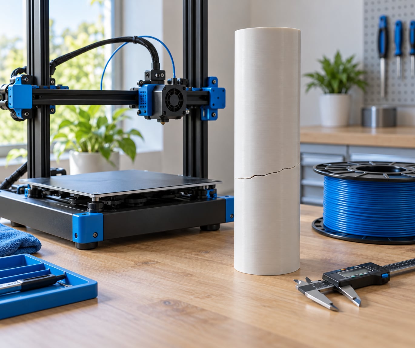
Height is the variable almost every guide leaves out. The bed sits about a centimetre under the first layer and never moves, so the bottom of the part stays warm and constrained while the top cools into open air. On a short print that gradient is small. On a 300 mm column it becomes the dominant force acting on the part.
The steps below run in the order I would work through them, because changing five settings at once is how printers stay broken. Most readers get through the first three in under twenty minutes with a small test coupon. The last two only matter once temperature and cooling are already handled.
Table of Contents
- What You Need
- Step-by-Step: How to Fix Cracking on Tall Prints
- 1. Identify where the cracking starts
- 2. Improve layer bonding with temperature
- 3. Control cooling between layers
- 4. Change the model orientation
- 5. Add or redesign supports
- 6. Reduce stress concentrations
- 7. Retest and document the settings
- Common Mistakes
- Adding bed heat for a crack at height
- Changing five settings in one go
- Pushing the nozzle temperature too high
- Leaving the part fan at full speed
- Relying on supports alone
- Printing damp filament
- Ignoring the geometry
- Frequently Asked Questions
- How do I repair a cracked 3D print?
- Can brittle PLA be saved?
- How do I fix poor layer adhesion?
- How can I fix a warped 3D print?
- Is a brim necessary, and what brim width should I use?
- What orientation gives the strongest part?
- Conclusion
What You Need
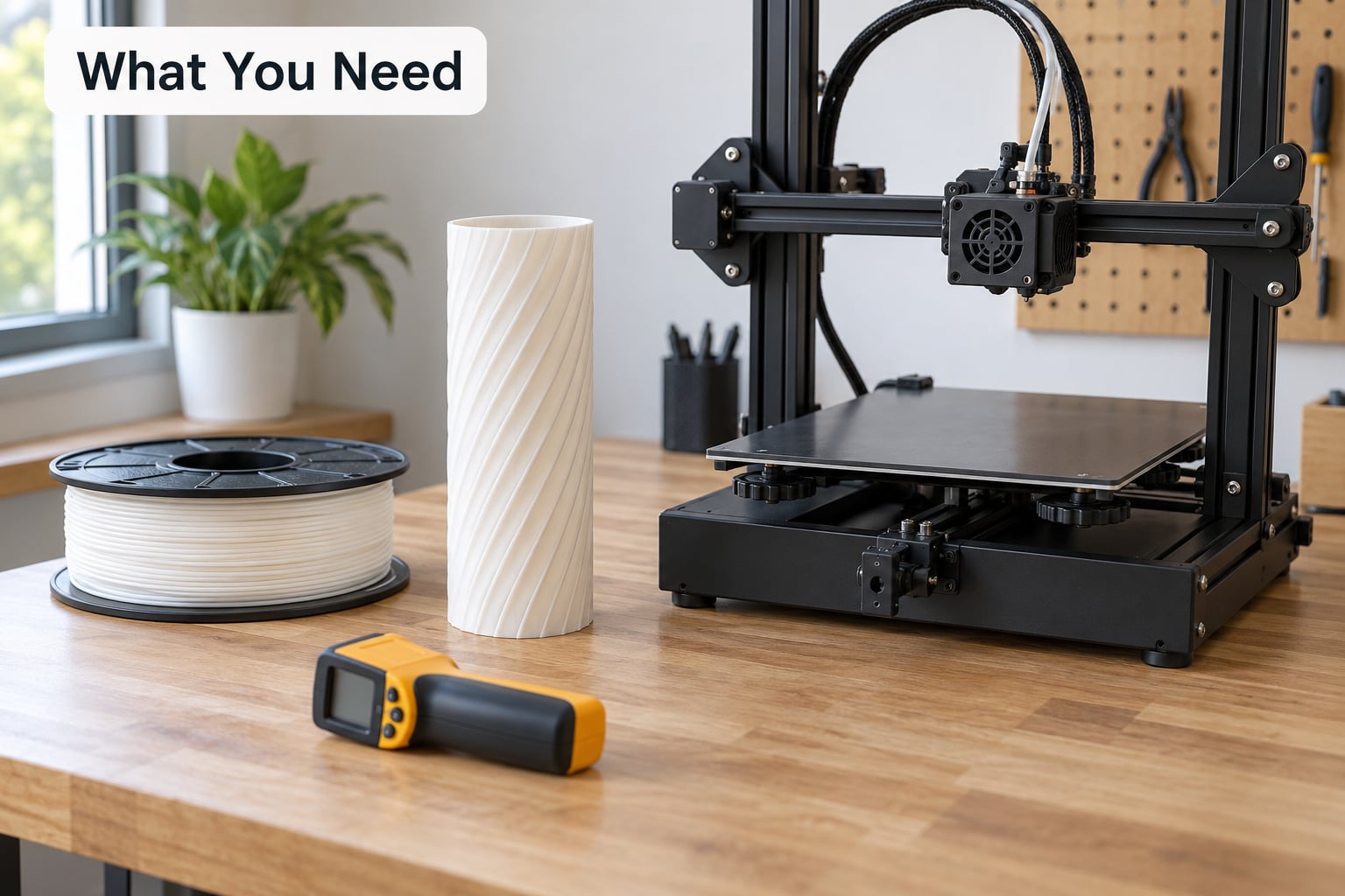
You need less than you would think. The diagnostics matter far more than the gear, so gather the print information before you touch a single slider.
- Your printer details — model, whether the frame is enclosed or open, whether the chamber is actively heated, and the maximum build height.
- Your filament details — type and brand, the nozzle temperature you are running, and how long the spool has been open. If it is nylon, PC or PETG, note when it was last dried.
- The failed print — keep it. The crack pattern is the single most useful piece of evidence you have.
- Bright light — a headlamp or desk lamp held behind the part reveals hairline splits that are invisible from the front.
- Callipers — measure wall thickness and the height of the split so you can tell a stress riser from a thin-wall problem.
- A test coupon — a thin tall tower, roughly 2 mm walls and 150 to 200 mm tall, printed at the same settings. This is your five-minute version of a 30-hour print.
- Optional — a box or shower-curtain draft shield for open-frame machines, PVA glue stick for the bed, and a filament dryer for hygroscopic materials.
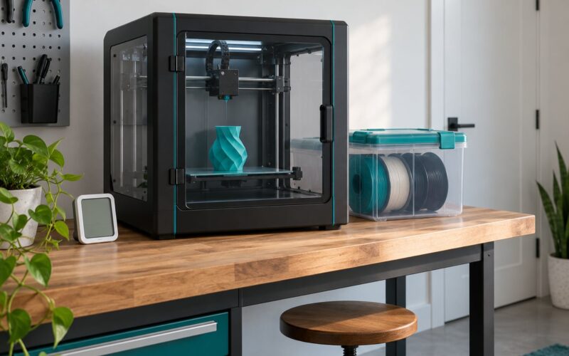
A note on draughts before you start. If you build an enclosure or a draft shield to keep heat in, you also need a way to vent ABS, ASA, polycarbonate and nylon fumes safely. Vent at the top of the enclosure with filtered extraction, never a fan pointed straight into the build volume. Airflow across the part is exactly the failure mode you are trying to remove.
Step-by-Step: How to Fix Cracking on Tall Prints
The order below matters. Temperature problems cause layer separation, cooling problems make it worse, and geometry decides whether the part survives the stress at all. Fix them top to bottom.
1. Identify where the cracking starts
A crack that runs horizontally along a layer line is layer separation. A part that lifts at the corners and bows upward is warping. Diagnose which one you have before changing anything, because the fixes barely overlap.
Shine light through the part from behind and follow the split. Note the height, whether it runs horizontally between layers or vertically up a wall, and which wall it sits on. Then match it to the table below.
| What you see | Likely cause | First thing to change |
|---|---|---|
| Horizontal split between layers, always at the same height | Thermal gradient from bed heat falling off with height | Chamber or enclosure temperature, then nozzle temperature |
| Split partway up one specific wall, not around the whole part | Stress riser at a corner, hole or abrupt section change | Add a fillet or gusset in the model |
| Corner lift and a bowed, banana-shaped part | Warping from bed adhesion failure | Brim, bed temperature, first-layer squish |
| Rough, under-extruded layers that feel spongy and split easily | Part fan or ambient airflow over-extruding cold plastic into the nozzle | Reduce fan, add a draft shield |
| Vertical crack running the full height of a thin wall | Wall too thin relative to the load, plus layer adhesion weakness | Thicken the wall, raise nozzle temperature |
| Cracks plus popping, bubbling or rough surface on PC or nylon | Wet filament | Dry the spool, then retest |
ABS cracking on tall parts usually turns up somewhere between 25 mm and 100 mm of height, once the upper layers sit beyond the reach of bed heat. If your split always lands near the same measurement, that repeatability is your confirmation that this is thermal rather than random.
2. Improve layer bonding with temperature
Raise the nozzle temperature in 5 °C steps, staying inside the manufacturer’s range for your filament. The goal is a hotter bead that is still solid enough to hold shape at the next layer.
Then attack the chamber. Bed heat does almost nothing for the top of a tall part. An actively heated chamber is the real fix for ABS and ASA, and a well-insulated box is the cheap approximation of one.
| Material | Typical nozzle range | Fan | Chamber target on a tall print |
|---|---|---|---|
| PLA | 200 to 215 °C | 30 to 50 % | No target, keep it out of a hot chamber |
| PETG | 230 to 250 °C | 20 to 40 % | 25 to 35 °C in a well-insulated box |
| ABS or ASA | 240 to 260 °C | 0 to 20 % | 40 to 50 °C |
| Polycarbonate or nylon | 260 to 290 °C | 0 to 10 % | 40 to 50 °C plus a dried spool |
| TPU | 220 to 235 °C | 30 to 60 % | Keep it cool, TPU barely cracks |
Pre-heat the bed and let the whole machine soak before the print starts. Ten minutes at temperature with the chamber door closed gives the metal frame time to stop pulling heat out of the air. On a cold machine you are chasing a moving target all night otherwise.
One warning: most enclosed printers warn against temperatures above roughly 35 °C because of heat creep in the Z axis. Check your printer manual before you set a chamber target. If it has no chamber heater, insulating the frame and closing off every gap does more than a plastic cover draped over the top.
3. Control cooling between layers
Reduce or disable the part cooling fan on materials that crack. The nozzle is the only heat source reaching layer 200, and a fan pointed straight at a fresh layer removes that heat before the bead can fuse.
Most slicers give you a fan curve rather than a single speed. Set fan to zero for the first several millimetres of the layer so the base stays hot, then ramp to your target rather than starting at full speed from the first perimeter. Where the setting lives depends on your software: PrusaSlicer and OrcaSlicer use per-filament overhang fan thresholds, Cura uses Fan Speed and Minimum layer time under Cooling, and Bambu Studio exposes fan speed on the filament profile.
If turning the fan down leaves the surface glossy and weak-looking, you have gone slightly too far, and the fix is a slower outer wall speed rather than more air. In PrusaSlicer and OrcaSlicer that is External Perimeter Speed. Slower walls give the previous layer longer to bond with the new one.
Block ambient draughts as well. A room with a door opening, a desk fan or an air conditioning vent pointed at the bed will undo a good chamber setup every time you are not watching. A simple cardboard box or a shower curtain over an open-frame printer solves this cheaply and needs no printer knowledge.
4. Change the model orientation
Rotating a tall part can move the load off the weak axis. FDM prints are strongest along the layer lines and weakest between them, so a part that hangs with its long axis vertical depends entirely on interlayer bond strength. Turn it so the long axis lies along X and Y instead.
There is a real cost. A horizontal part on a small printer will not fit, a lying-down part needs more supports under its overhangs, and the usable height of the build volume drops. Sometimes you lose more to support scarring and clearance than you gain in strength.
A useful middle ground is a 30 to 45 degree tilt. It breaks up the tall vertical span, keeps the part within most build volumes, and cuts the crack height roughly in half. Check the clearance against your gantry before committing to a multi-day job.
5. Add or redesign supports
Supports help with overhangs and with giving a fragile section a load path, but they cannot repair a layer-bonding problem. A well-supported print with a cold nozzle still delaminates. Treat supports as a structural fix, never as a thermal one.
For tall parts that still split, what usually works is regular structural supports from the bed upward rather than standard auto-generated trees. Sparse, low-density supports at regular vertical intervals give the part something to resist bending against. The combination that resolves repeated cracking in practice is ribs in the model, a warm enclosure, and a brim that holds the base flat.
Adhesion features belong to the base layer, and that is a separate problem from cracking at height. A brim or a raft helps a part that is lifting at the edges. Mouse ears help on small ABS parts where warping starts in one corner. None of them reach the upper layers, so if your split is 180 mm up, put your effort into temperature and geometry instead.
6. Reduce stress concentrations
Add fillets to sharp internal corners. A 90 degree corner concentrates stress in a tiny volume, and the same stress spread through a 3 mm radius stops generating cracks. Gussets and ribs do the same job for flat walls and thin sections.
Reduce abrupt cross-sectional changes. A wall that steps from 4 mm to 1 mm in one layer is a crack waiting to happen. Taper the transition over 10 to 20 mm and the part has room to flex.
Thicken thin walls. A tall part with 1.2 mm walls has almost no margin, because layer height eats a large share of the section. Two walls or three walls give you a section that can carry load without depending entirely on the interlayer bond.
When nothing else reaches it, print the model in sections and bond the parts. Tall models on small printers get printed in two halves and glued, and with careful registration plus epoxy it works for enclosure bodies and stands. Model a small chamfer or alignment lip at the joint so the parts self-locate, print each half with its own flat side down, and clamp with glue or epoxy. This trades a little strength for the elimination of the tall build entirely.
7. Retest and document the settings
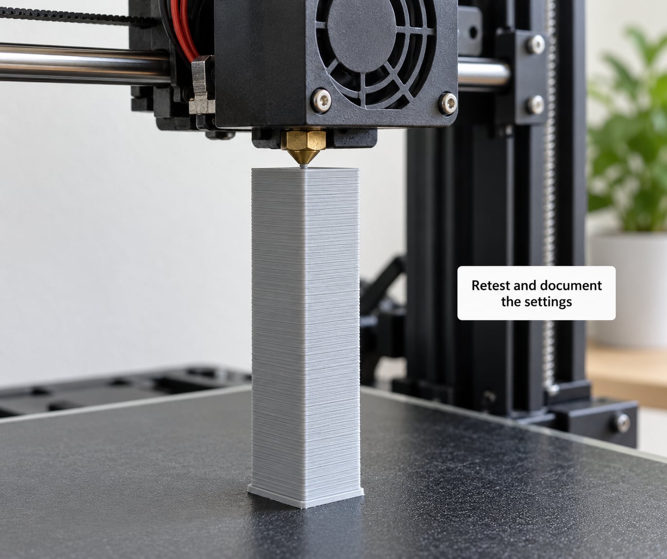
Change one variable at a time and print the coupon. Twenty minutes of coupon testing is cheaper than finding out at hour twenty of a 30-hour print.
The coupon is a thin tall tower, about 2 mm walls, 150 to 200 mm high, printed with the same layer height, walls and infill as the real part. Print it in a corner of the plate or on a second machine if you have one. Inspect it under a bright light from several angles, then try to flex the split area gently by hand. A sound part bends a little and returns. A weak one clicks.
Write down what you changed and what happened. Slicer settings get lost, and the second time you face the same crack you will want to know whether the nozzle bump or the fan change was the fix. If the coupon passes, run the full print.
One last check before a long job: confirm the first layer is properly stuck by nudging the plate. Strong bed adhesion is not automatically good. A part held down rigidly by an aggressive brim is restrained, and restraint adds stress to the upper layers. If the plate flexes and the part moves at all, ease off before you start.
Common Mistakes
Most cracked tall prints have been sitting on a bed at a higher temperature for a week. These are the fixes that waste the most filament.
Adding bed heat for a crack at height
Bed temperature influences the first few millimetres. Past roughly 100 to 150 mm the heat simply is not there, so a bed at 110 °C changes nothing about a split at 220 mm. Use chamber or enclosure heat for upper-layer cracks, and save bed heat for corner lift at the base.
Changing five settings in one go
If you raise the nozzle temperature, drop the fan, add an enclosure and rotate the model, and the crack moves, you learn nothing. Change one variable, print the coupon, record the result. Slow diagnosis beats failed multi-hour prints.
Pushing the nozzle temperature too high
Extra heat above the recommended range softens previous layers, blurs detail, creates stringing and can cause heat creep or a clog. Step up in 5 °C increments and stop when the coupon stops improving.
Leaving the part fan at full speed
A fan aimed at a tall, slow print removes heat continuously. On ABS and ASA it should be at or near zero above the first layers. On PLA, keep some airflow to hold overhangs and slow the outer wall speed instead.
Relying on supports alone
Supports carry load and fix overhangs. They do not raise the interlayer bond strength. If the coupon splits without supports removed, the problem is thermal, and no support pattern will change that.
Printing damp filament
Nylon, polycarbonate, PETG and some ABS absorb water from the air. The water boils in the nozzle, the bead expands unevenly and the layer never bonds properly. Dry the spool first, then rule it out as a cause before retesting anything else.
Ignoring the geometry
Sharp internal corners, thin walls and abrupt steps generate more stress than a perfect thermal setup can absorb. If a part still splits after the temperature work, change the model rather than the slicer.
Frequently Asked Questions
How do I repair a cracked 3D print?
For a cosmetic split, clean both faces, roughen them lightly, and run CA glue into the crack. For a structural part, use two-part epoxy, clamp it, and let it cure for a full 24 hours. PLA that split along a single layer line can sometimes be re-fused with gentle heat about 10 to 15 °C below glass transition, pressed between flat plates.
Can brittle PLA be saved?
Usually for light-duty parts only. PLA already loses strength from heat and UV long before it cracks, so a salvaged piece is rarely as strong as a reprint. Glue or epoxy works for display items and prototypes. If the part carries real load, print it again in PETG, which bonds better and tolerates more heat, or add ribs so a crack cannot travel.
How do I fix poor layer adhesion?
Raise nozzle temperature in 5 °C steps toward the top of the filament range, then drop the part cooling fan to zero for the first several millimetres of each layer. Slow the outer wall so the previous layer gets more time to bond. Clean stringing off the nozzle, since a draggy bead ruins adhesion. Test on a two-layer tower before committing.
How can I fix a warped 3D print?
Small PLA warps often relax with gentle heat. Lay the part flat, cover it with a glass or acrylic sheet, warm it slowly with a heat lamp or hair dryer, and leave it clamped until cool. Larger ABS or ASA warps may need an oven roughly 15 °C below glass transition. A thin film of glue stick on the plate stops the part tearing as it lifts.
Is a brim necessary, and what brim width should I use?
Only when the base layer struggles to stick: large flat footprints, small contact area, ABS and ASA, or a heated chamber pulling heat from the plate. Start at 8 mm for PLA and PETG, and 15 to 25 mm for ABS and ASA on a wide footprint. Wider brims waste material without adding much. A brim fixes base lift, never cracks at height.
What orientation gives the strongest part?
Strength comes from layer lines, so orient the part so the main load runs along X and Y rather than Z. Lay a tall column down, or tilt it 30 to 45 degrees to halve the crack height. A vertical print is only as strong as its interlayer bond, which is the same weak link that splits in the first place. Check gantry clearance before rotating.
Conclusion
Start by identifying the crack. A horizontal split at a repeatable height is thermal, and the fix is chamber temperature, higher nozzle temperature and less cooling between layers. A split on one wall only is geometry, and the fix is a fillet, a thicker wall or a change of orientation.
Then prove it on a 150 mm coupon before you commit to the tall print. Knowing how to fix cracking on tall prints is mostly knowing which cause you are dealing with, and the crack pattern tells you that before you change a single setting.