Ringing is the name for those repeating ripples that show up on a surface right after a sharp corner, and ghosting is the same defect described as echoes that trail a corner and fade out over a few millimeters. Both come from the same root cause: your printer’s frame and toolhead keep oscillating after the head changes direction, and the nozzle is still extruding while it does. Most cases are fixed by tightening the mechanics first, lowering acceleration second, and running a measured input shaper last.
The fix order matters more than any single setting. If you enable input shaping on a printer with loose belts or a hollow desk, you are compensating for a mechanical problem with software, and the calibration will drift again the moment you touch a belt. This guide walks through how to fix ringing and ghosting on prints in that order, with the diagnostic steps first so you know which problem you actually have.
Table of Contents
- What You Need
- Step-by-Step: How to Fix Ringing and Ghosting on Prints
- Step 1: Identify Whether the Defect Is Ringing, Ghosting, or Both
- Step 2: Reproduce the Problem With a Controlled Test Print
- Step 3: Check Input Shaping Before Changing Every Speed Setting
- Step 4: Reduce Acceleration and Speed Until the Echo Disappears
- Step 5: Fix Temperature, Flow, and Retraction Problems
- Step 6: Inspect the Printer for Mechanical Causes
- Step 7: Retune Gradually and Verify With a Fresh Test
- Common Mistakes
- Frequently Asked Questions
- Does input shaping remove ghosting completely?
- Does low nozzle temperature cause ringing?
- I already have input shaping, so why is my ghosting still there?
- Which setting should I change first to reduce ghosting?
- Does print speed cause ringing?
- What do I do when the artifact survives very slow printing?
- Conclusion
What You Need
You do not need new hardware to start. You need the printer itself, the slicer you actually use, one calibration model, and a way to see surface detail clearly.
- A ringing test model. A ringing tower, the Voron Cube, or a Benchy all work. A tower with tall vertical walls and sharp corners shows the defect fastest.
- Good side lighting. A desk lamp held low and shining across the wall at a shallow angle makes ripples obvious even when they are faint in daylight.
- Your slicer and firmware versions noted down. This is the step people skip, and it is the reason the same fix goes by three different names depending on who you ask.
- An accelerometer, if your printer does not ship with one. An ADXL345 module on a rigid mount is the common choice for Klipper builds.
- A multimeter or tension gauge, optional. Useful for checking frame rigidity rather than only belt feel.
Check firmware and slicer versions first, because the input-shaping controls sit in completely different places depending on the software. PrusaSlicer exposes input shaping per printer profile under Machine settings, Bambu Studio hides most of it behind the calibration and HMS menus, Cura and OrcaSlicer use per-feature acceleration instead, and Klipper runs it as firmware macros with its own measurement commands. Marlin-based boards have input shaping available only on recent builds and it is off by default.
Step-by-Step: How to Fix Ringing and Ghosting on Prints
Step 1: Identify Whether the Defect Is Ringing, Ghosting, or Both
Ringing shows up as evenly spaced waves that begin a few millimeters after a corner and die out. Ghosting is the broader word for any leftover outline or duplicate edge that repeats after a direction change, including the echo on the far side of a small hole or the doubled edge around text. They are the same physical event described at different scales, and they often appear together on the same print.
Check the pattern against these lookalikes before you change a single setting. Confusing ghosting with a layer shift is the most common reason people spend days fixing the wrong thing.
| Defect | What it looks like | Where it shows first |
|---|---|---|
| Ringing / ghosting | Evenly spaced ripples fading out, or a repeated outline offset from the real edge | Immediately after sharp corners and direction changes |
| Layer shift | A hard step where the whole layer is displaced, usually a consistent offset | Sudden, often at the same height every time |
| VFA (vertical fine artifact) | Streaks running down the wall, wider in X than in Y | Tall vertical walls, usually print speed related |
| Stringing | Thin hairs between features and across the top surface | Between posts, bridges and overhangs |
| Salmon skin | A wavy, uneven texture across flat top surfaces and first layers | Top surfaces, not vertical walls |
| Under-extrusion | Coarse walls, gaps, visible layer lines through the wall | Anywhere, usually consistent across the print |
A quick test: if the artifact only appears on surfaces created by perimeter moves and follows the contour of the part, it is motion-related. If it appears on flat horizontal faces with no corner nearby, look at temperature and flow instead.
Step 2: Reproduce the Problem With a Controlled Test Print
Print one small model instead of guessing from the last 14-hour job. Choose a calibration model that includes straight vertical walls, sharp 90-degree corners, a curve or cylinder, solid infill and a flat top surface, so every failure mode shows up in a single print.
Write down what you used: layer height, wall thickness or line count, nozzle temperature, print speed, acceleration, jerk or junction deviation, flow multiplier, retraction distance and speed, and whether input shaping is currently active. This list is your baseline, and every later comparison is meaningless without it.
Keep material and temperatures identical across tests too. Changing filament spool and acceleration in the same run makes the result useless, which is exactly what happens when people chase this for a fortnight.
Step 3: Check Input Shaping Before Changing Every Speed Setting
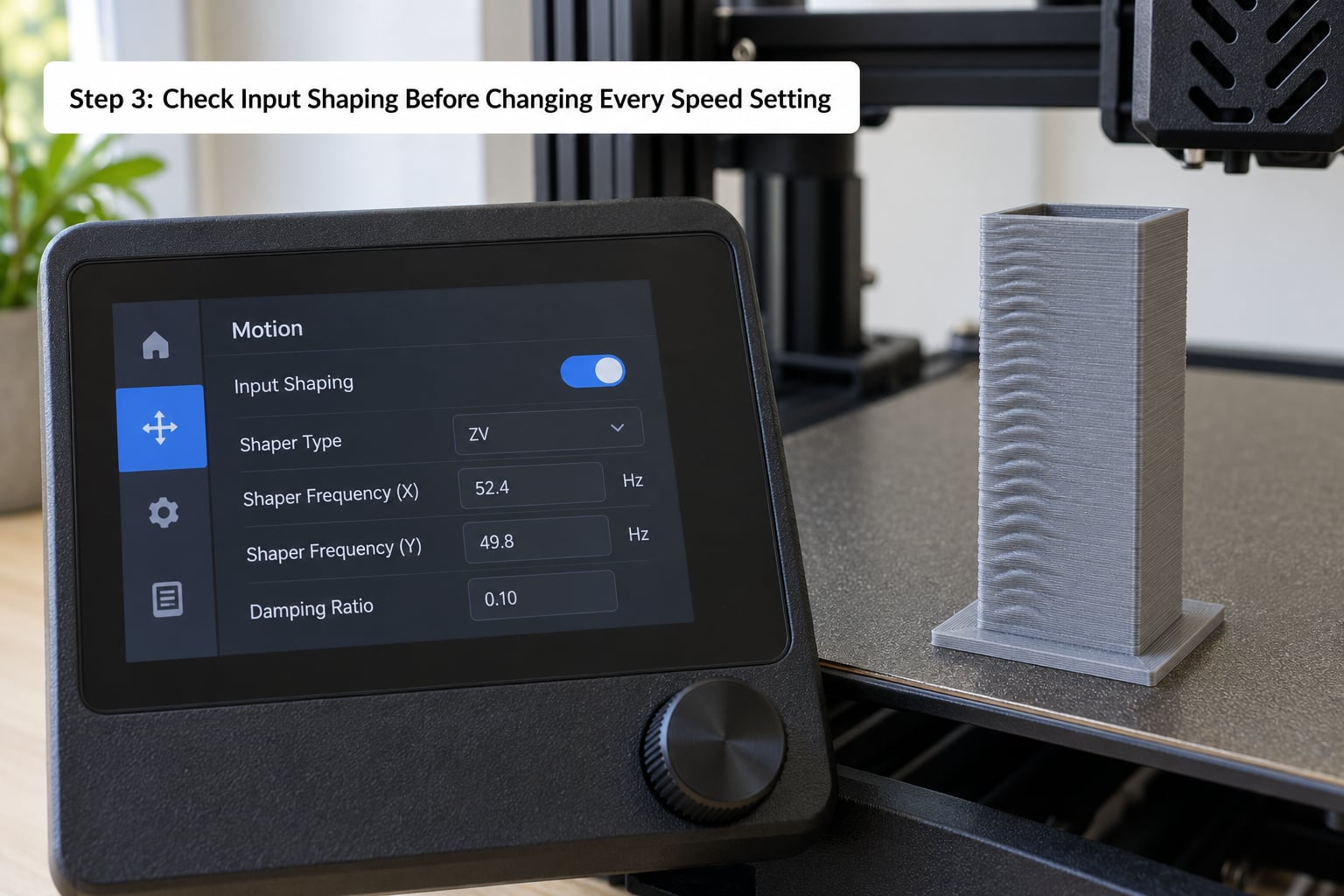
Start by finding out what input shaping your printer is already doing, because most printers from the last few years ship with some form of it, and many owners never checked whether it is calibrated for their own machine.
- Klipper. Run
SHAPER_CALIBRATE_AXISfor X then Y with the accelerometer mounted rigidly. Read the recommended frequency and damping values it prints and set them in the[input_shaper]section. The shaper type (ZV, MZV, EI, 2HUMP_EI, 3HUMP_EI) is chosen automatically; changing it by hand only makes sense if you understand the residual vibration trade-off. - Auto-calibrating consumer printers. Bambu Studio, Creality K1 and similar machines measure resonance at startup. Confirm the measurement is passing and not silently failing due to a bad sensor reading.
- Marlin builds. Input shaping may exist but be disabled. Enabling it with a copied shaper frequency from another printer is one of the most common mistakes, and it usually produces no change at all.
- No accelerometer. You can run the tower test at two very different accelerations and compare, but you cannot get a real frequency reading. Measuring is better than guessing.
Whatever the source of the numbers, use the frequency measured on your own printer. Resonance depends on frame material, belt tension, moving mass and even which desk the printer sits on, so a value from a forum post is data about someone else’s machine.
If the accelerometer is held on with tape or a zip tie, the measurement picks up mount flex instead of toolhead motion and the calibration is close to meaningless. Bolt it or screw it to a rigid surface, or accept that the reading is only approximate.
Step 4: Reduce Acceleration and Speed Until the Echo Disappears
Acceleration is the lever that matters. Print speed is what most people change first, which is why lowering speed alone often feels like it does nothing. Corners are where acceleration events happen, and a lower acceleration means a gentler direction change with less overshoot.
Drop one setting at a time and reprint the same model. A useful starting point for a typical FDM printer is an acceleration in the range of 500 to 1500 mm/s² and jerk, on Marlin-style firmware, around 5 to 8 mm/s; on Klipper, a junction deviation setting replaces the jerk value entirely. Treat those as starting points rather than answers.
| Printer class | Acceleration | Perimeter speed | Notes |
|---|---|---|---|
| Bed slinger, stock firmware | 500 to 1000 mm/s² | 40 to 60 mm/s | Input shaping often absent; mechanical fixes carry the most weight here |
| Bed slinger with Klipper | 1000 to 2000 mm/s² | 60 to 100 mm/s | Measure per axis; X and Y rarely share a frequency |
| CoreXY with input shaping | 3000 to 8000 mm/s² | 150 to 250 mm/s | Ringing that reappears after any hardware change means recalibrate |
| Auto-calibrating consumer printer | Use the measured default | 100 to 200 mm/s | Residual ghosting here is nearly always mechanical, not shaper-related |
Lower the initial layer speed separately, since a poor first layer makes every later measurement noisy. And lower only the external perimeter speed first rather than the whole print, because on most parts the outer wall is where the artifact is visible and it is a small time cost.
If the ringing disappears at low acceleration, you have confirmed a motion resonance. If it survives a very slow print, stop here and move to Step 5 and Step 6, because something other than motion is involved.
Step 5: Fix Temperature, Flow, and Retraction Problems
Not every artifact that looks like ghosting is motion. Temperature and flow defects can leave a raised line or a duplicated edge that mimics an echo, especially on cylindrical parts and small holes.
- Nozzle temperature too low. Under-extruded layers leave gaps and ridges. Raise the temperature in 5-degree steps and watch for stringing as the upper limit.
- Wet filament. Bubbles and inconsistent flow cause seams and blobs at corners. Dry the spool and print again before touching anything mechanical.
- Partial clogging. A gunked nozzle extrudes inconsistently, so corners and seam areas show raised or missing plastic. Do a cold pull and clean the nozzle before suspecting the frame.
- Retraction. Too much retraction or a retraction distance tuned for a Bowden setup on a direct drive extruder can leave a visible scar at the start of a line. If the artifact always begins in the same spot on the seam, this is the likely cause.
- Flow multiplier off. Underextrusion makes each layer sit slightly inside the last one, which reads as a stepped or doubled wall rather than a wave.
Pressure advance and linear advance affect corners and seams too, though not the post-corner ripples that define ringing. Set those after the mechanical and motion work is settled.
Step 6: Inspect the Printer for Mechanical Causes
This is the step that fixes the machines where input shaping already exists and the ghosting is still there. Every software compensation assumes the machine underneath behaves predictably.
- Belt tension. Pluck each belt and compare the note and decay to the other belt. A loose X or Y belt allows overshoot that no shaper will fully hide. Tighten evenly, do not crank them tight, because overtightening loads the bearings and moves the resonance frequency again.
- Frame rigidity and the surface under the printer. Push gently on the gantry and the frame and watch for movement. A hollow desk or a desk with casters lets the whole machine ring. Anti-vibration pads or a heavy base under the printer help; forum users report consistent gains from both.
- Gantry alignment and loose pulleys. On Cube and bed-slinger frames, an out-of-square gantry prints corners as doubles on two axes at once.
- Worn rods or bearings. Slop in the linear rails shows up as repeating ripples whose spacing stays constant while the part is printed at a steady speed.
- Moving mass. Direct drive extruders add weight to the carriage that a Bowden setup does not, which lowers the resonance frequency and makes ringing worse. A lighter extruder or a lighter toolhead helps, at the cost of some retraction precision.
Do not loosen belts or take apart structural components without checking with the printer manufacturer first. Every mechanical change, including a new belt set or a different bed, invalidates an existing input shaping calibration, so recalibrate after any of this work.
Step 7: Retune Gradually and Verify With a Fresh Test
With the mechanics settled and input shaping measured, raise acceleration or perimeter speed in small steps, about 10 to 15 percent each time, keeping the model, material, temperatures and layer height identical. Two changes at once tell you nothing about which one worked.
You are done when the wall after a sharp corner is flat, there is no duplicated outline following a direction change, the corner reads as a single clean line, and the flat top surface has consistent texture with no rippling. Judge it under raking light, not from a normal viewing angle, or you will call a slightly wavy wall clean.
Print a Benchy at the end if you want a reference image to compare against later. Any remaining artifact that shows up mainly on the cabin roof and bow hull is a tuning limit on a given machine, not a fault you can tune away, and chasing it further costs more than it returns.
Common Mistakes
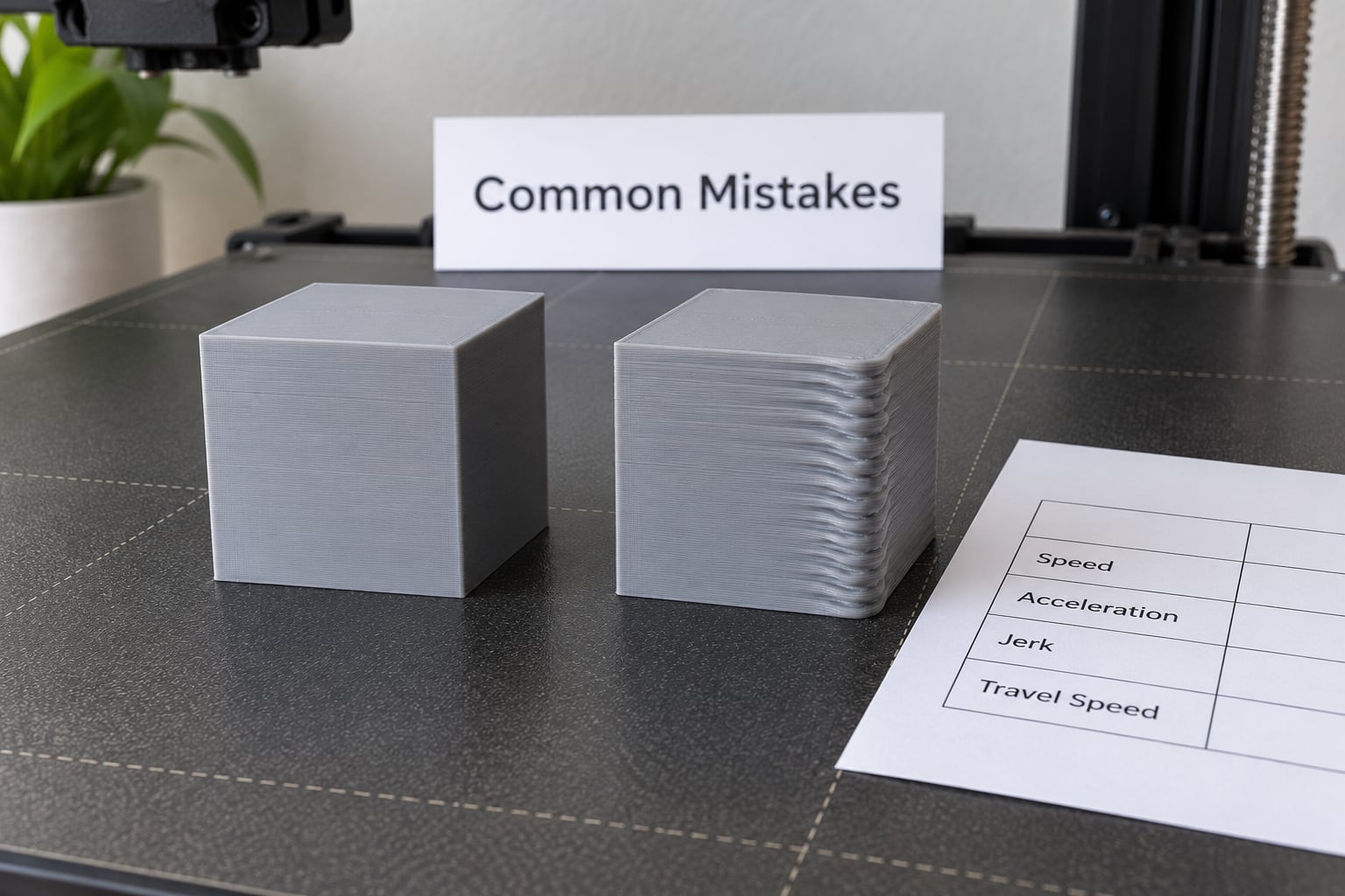
Almost every long troubleshooting thread on this topic contains one of these six mistakes, and each one sends you in the wrong direction.
- Changing every setting at once. Lower acceleration, raise temperature, tighten belts and enable input shaping, then print once. The result tells you nothing. Change one variable per test print and note what moved.
- Raising acceleration to compensate for ringing. Higher acceleration produces more overshoot, not less. Ringing after a corner is a reason to go slower, never faster.
- Disabling input shaping without recalibrating. If you turn it off, also remove the shaper parameters. Leaving stale frequency values behind causes confusing behaviour when you switch it back on.
- Copying a shaper frequency from another machine. Resonance is specific to your frame, your belt tension and your table. Read the value your own accelerometer reports.
- Judging the result from one wall or one corner. Ringing can be axis-specific, so an X-only problem is invisible on a test that only moves in Y. Print the full calibration model each time.
- Changing temperatures before checking filament and hardware. A clogged nozzle and a loose belt both look like corner artifacts from a distance. Check the cheap physical causes first.
Two more worth naming: mounting an accelerometer with tape, and over-tightening belts while trying to fix a resonance problem. Both feel productive and both move the problem somewhere worse.
Frequently Asked Questions
Does input shaping remove ghosting completely?
No. Input shaping cancels the motion commands that trigger vibration, but it cannot correct a loose belt, a hollow desk or a worn bearing. On printers with automatic resonance calibration, any remaining ghosting is almost always mechanical rather than a failure of the shaper. Fix belts, frame stability and moving mass first, then calibrate the shaper again.
Does low nozzle temperature cause ringing?
Low temperature does not cause ringing. Ringing is a motion artifact driven by acceleration and resonance. Low temperature causes under-extrusion, gaps and stringing instead. The two can be confused on cylindrical parts and around holes, where a badly extruded corner looks like a duplicate outline. If the artifact persists at very low speed and low acceleration, suspect temperature, flow or a partial nozzle clog.
I already have input shaping, so why is my ghosting still there?
Four things usually explain it. The shaper frequency was copied rather than measured, the accelerometer was mounted flexibly and produced bad data, the shaper was calibrated before a belt or hotend change, or the real cause is mechanical. On a printer with auto-calibration, remaining ghosting is nearly always mechanical. Re-measure the resonance after any hardware change, and re-test at low acceleration to separate motion from mechanics.
Which setting should I change first to reduce ghosting?
Acceleration. Ringing is triggered at direction changes, and acceleration governs how hard those changes happen. Halve your acceleration and reprint the same test model; if the ripples shrink or vanish, you have confirmed a motion resonance. Only then work upward. Print speed matters far less here, which is why lowering it alone often produces no visible change.
Does print speed cause ringing?
Speed contributes indirectly. Higher speeds leave less settling time after a corner, so any residual oscillation has more time to record itself on the surface. Acceleration is the dominant factor, not raw speed. Lower only the external perimeter speed first on most parts, since that is where the artifact shows and it costs very little time in a full print.
What do I do when the artifact survives very slow printing?
Stop tuning motion settings and check the physical causes. A defect that appears at 25 mm/s is not a resonance problem. Inspect nozzle temperature and filament dryness, pull and clean the nozzle for partial clogging, then check belt tension, gantry alignment and the stability of the surface the printer sits on. Bring the speed back up slowly once a clean baseline print is confirmed.
Conclusion
Start with one small calibration print and read the pattern. Ripples that begin after a corner are motion, so settle the mechanics, then measure your printer’s own resonance and use those numbers for input shaping, then bring acceleration and perimeter speed back up one step at a time. The permanent fix is the smallest change that removes the artifact while keeping print time reasonable, and any mechanical work you do along the way means calibrating the shaper again afterward.