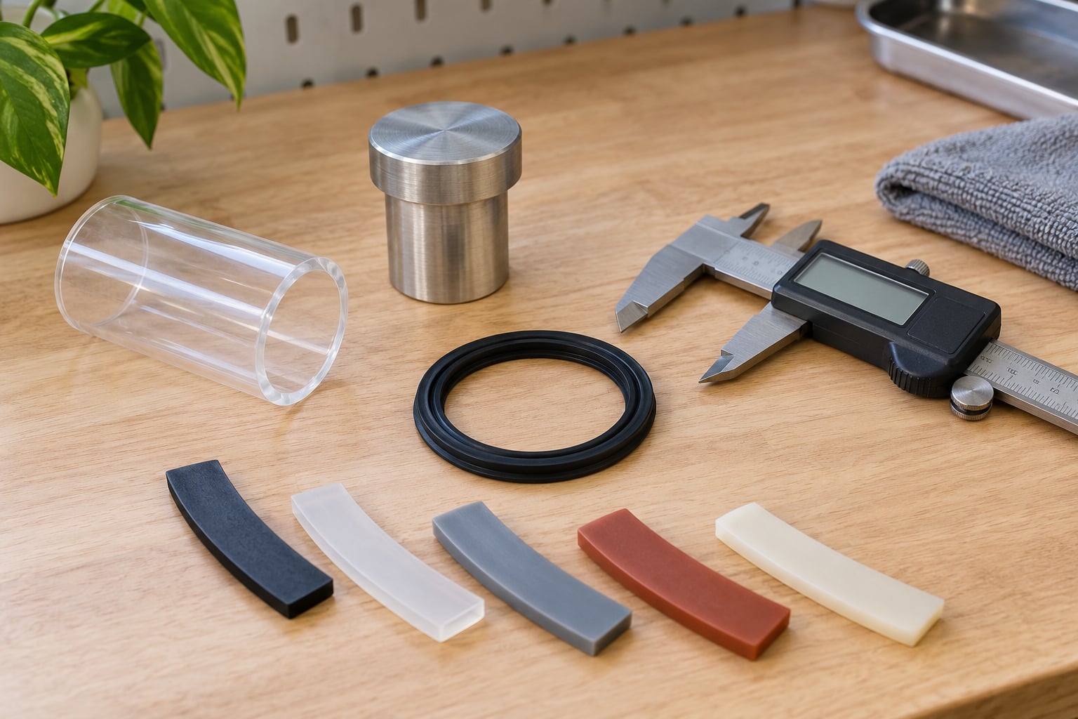
Yes, a 3D printer can make a working gasket or seal, provided you print it in an elastic material like TPU and give it somewhere to compress. When I explain how to print gaskets and seals to people, it always comes down to three routes: print the seal directly in flexible filament, print a rigid prototype to test the fit, or print a mould and cast silicone into it. Whichever route you take, the seal only works if every layer line is fully fused and the part has enough compression to fill the microscopic gaps between mating surfaces.
That last part is where most attempts fail. People get a clean print, bolt it in, and find a slow drip a week later. Almost always the cause is one of three things: layer adhesion that never fully bonded, a groove sized with no tolerance thought, or a geometry that sits under-compressed. Everything below is the process I would follow to avoid all three.
Before starting, it helps to know what you are actually sealing. A gasket is a compliant ring or sheet placed between two mating surfaces to make a joint fluid-tight or airtight. A seal is the wider category: anything that stops fluid, gas, dust or contaminants crossing a gap. An O-ring is the round, toroidal member of that family. Knowing which one you need tells you whether you need a static squashed seal or something that survives sliding motion.
Table of Contents
- What You Need to Print Gaskets and Seals
- Three routes to a printed seal, compared
- Step-by-Step: How to Print Gaskets and Seals in TPU
- 1. Define the Sealing Requirements and Process
- 2. Model an Effective Gasket Geometry
- 3. Choose and Prepare the Right Material
- 4. Orient, Support, and Slice the Part
- 5. Print a Small Calibration or Test Part
- 6. Finish and Inspect the Printed Seal
- 7. Fit, Cycle, and Leak-Test the Seal
- Common Mistakes
- Frequently Asked Questions
- What is the best material for 3D printed gaskets and seals?
- Can you print a waterproof gasket with TPU?
- Are resin 3D printers suitable for making functional seals?
- How do I stop a 3D printed gasket from leaking between layers?
- Can 3D printed seals replace molded rubber or commercial O-rings?
- Conclusion
What You Need to Print Gaskets and Seals
You need five things, and only one of them is the printer. The rest are what separate a part that seals from a part that only looks like it seals.
Application data. Write down the gap, the pressure or vacuum, the operating temperature, the fluid in contact, whether anything moves, and how long the seal has to last. Compression, temperature, chemical resistance and surface finish all follow from this list, and they decide the material. If you skip this step, you are guessing.
Geometry data. A CAD model you drew yourself, a scan of the existing gasket, or at minimum a caliper measurement of the groove and the mating surface. If the original part is gone, measure the groove it sits in, not the part itself, and allow extra clearance for printer tolerance.
Modelling and slicing tools. Anything from a free parametric option up to a full CAD suite works. For sealing faces, switch on any gasket or sealing-surface analysis your package offers. It flags faces that fall outside what the process can hold accurately, which is exactly the failure you want caught on screen rather than under a tap.
A printer suited to flexible filament. A direct drive extruder is strongly preferred. Bowden machines can run soft TPU with changes, and I cover those in the mistakes section, but if you have never printed flexible filament before, direct drive will save you a weekend.
Measuring and test gear. Digital calipers, a feeler gauge, and a way to test the finished joint. A plastic tub, water, dish soap and a short length of clear tube is enough to leak-test a low-pressure water seal at home.
Three routes to a printed seal, compared
| Route | What you make | Best when | Main limit |
|---|---|---|---|
| Direct TPU print | The seal itself in 95A or 85A flexible filament | Low to moderate pressure, water, air, dust, vibration, prototypes | Temperature ceiling well below rubber; not for fuels or certified duties |
| Rigid prototype | A fit-check part in PLA, PETG or nylon | Checking groove depth and clearance before committing | Hard and incompressible, so it proves fit but not sealing |
| Printed mould | A rigid mould you cast silicone into | You need real rubber properties at low volume | Two processes plus cure time, and the mould must vent properly |
Choose route three when the joint sees heat, oil or repeated cycling that printed TPU will not survive. Cast silicone has a far wider temperature range and resists permanent deformation, and the mould only needs to be accurate at the sealing face because the rubber does the conforming.
Step-by-Step: How to Print Gaskets and Seals in TPU
1. Define the Sealing Requirements and Process
Document the gap, the compression range you can work with, the pressure or vacuum, the operating temperature, the fluid exposure, the movement, and the required service life. Then pick a process that fits those numbers rather than defaulting to extrusion.
Extruded elastomers are the sensible default for gaskets: TPU compresses elastically, holds a modest pressure range, and tolerates abrasion and repeated cycling. Rigid resins are a different tool entirely. A resin print gives excellent dimensional accuracy and surface finish, but a rigid part does not compress, so it is a fit-check part, a spacer or a mould, not a seal.
Decide now when a molded, machined or overmolded part is the safer answer. Automotive head gaskets, high-pressure hydraulics, food-contact and medical parts, and anything safety-critical all belong in that category. Print a prototype to validate the fit, then send the model to a rubber supplier for the real part.
2. Model an Effective Gasket Geometry
The geometry decides whether the part seals, so this is where the real work is. Every dimension you draw has to account for printer tolerance, material shrinkage, layer direction, support scarring, and the compression the elastomer undergoes once installed.
Build the groove first, then the part that sits inside it, so you can size for compression rather than for a nominal fit. As a starting point, size a static seal so it is squeezed roughly 15 to 25 percent in its groove. That is a starting band, not a law. Softer 85A material takes more squeeze than 95A, higher pressure needs more, and a change in surface finish shifts it. Confirm with a test coupon instead of trusting a number you found online.
| Use case | Cross-section thickness | Target compression | Notes |
|---|---|---|---|
| Dust and light air seal | 2 to 3 mm | 15 to 20 percent | Fit and feel matter more than pressure holding |
| Water housing or irrigation fitting | 3 to 4 mm | 20 to 25 percent | Keep fillets generous so the corner does not cut |
| Repeat open-and-close cycling | 3 to 5 mm | 15 to 20 percent | Thicker sections resist compression set over time |
| Static pressure or vacuum | 4 mm and up | 15 to 25 percent | More material means less risk of tearing on install |
Shape the cross-section for the job. A flat rectangle is predictable and easy to print. A D-shaped or bulb profile is self-aligning and tolerates a wider tolerance band. Always fillet internal corners, because a sharp notch becomes both a tear starter and a leak path. Add lead-in chamfers so the part does not shave itself during installation.
For an O-ring groove, work backwards from the ring. Design the groove depth and width for a negative squeeze on the ring, then account for the swell your material gains once installed. A negative tolerance means the groove is deliberately tighter than the nominal ring and the elastomer fills it. Get that wrong in the loose direction and you end up with a part that fits perfectly and never seals.
Orientation matters as much as the profile. Lay the sealing face flat in the XY plane wherever you can. Layer lines then run across the face rather than through it, which means fewer continuous paths for water to track along. On a ring, print it vase-style with a single continuous perimeter so there is no Z-seam notch acting as a leak channel.
3. Choose and Prepare the Right Material
TPU is the default for a reason: it stretches, it springs back, and it survives being squashed and released many times. Shore hardness is the number that matters, and it is easy to misread. On the A scale, a higher number means a harder material. 95A is firm enough to hold a groove and easy to print. 85A is noticeably softer, takes more compression, and asks more of your extrusion setup.
| Material | Hardness | Where it fits | Watch out for |
|---|---|---|---|
| Polyether TPU 95A | Firm, elastic | Water, air and dust seals; general prototyping | Softens with heat; needs a dry spool |
| Polyether TPU 85A | Soft, high stretch | Tighter compression, face seals, vibration damping | Harder to extrude, tears if pulled off the bed |
| Polyester TPU | Firm to semi-rigid | Oil, grease and hydrocarbon exposure | Hydrolyses over time if moisture gets in; store sealed |
| TPC and PEBA blends | Firm to semi-rigid | Heat and chemical duty beyond basic TPU | Needs a hardened nozzle and higher temperatures |
| PETG | Hard, no give | Fit-check prototypes and rigid moulds | Not a seal; it will not compress |
| Nylon | Tough, slight give | Chemical-resistant prototypes and moulds | Hygroscopic, warps, hard to machine after printing |
| Rigid resin | Hard | Accurate fit checks, moulds, sacrificial forms | Brittle, needs thorough washing and curing |
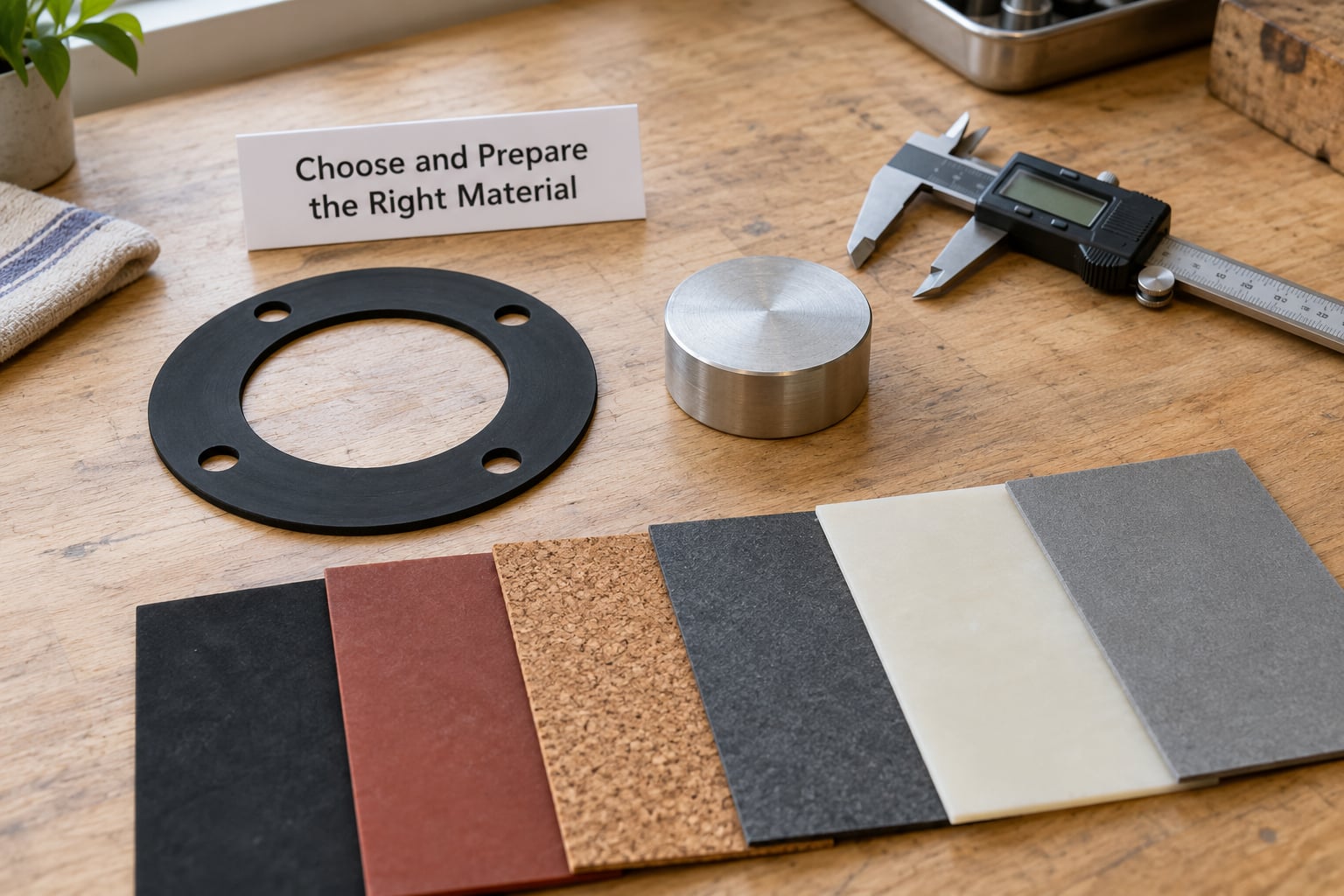
TPU absorbs moisture readily, and wet filament is the single most common reason a print goes wrong. A dry box or a filament dryer is not optional for this job. Listen for popping or a sizzling noise at the nozzle; that is water boiling off inside the melt. Dry the spool for several hours according to the dryer’s own guidance, print straight from the dry box if you can, and seal the spool again immediately afterwards.
One chemistry note that catches people out: polyether TPU is the better choice around water and humidity, while polyester TPU is the one for oils, fuels and hydrocarbons. Polyether TPU held up well in oil in a maker report I read, where PETG failed badly in the same joint, but treat that as a signal to match your chemistry rather than a blanket endorsement.
4. Orient, Support, and Slice the Part
How you slice the seal matters as much as the settings you type into it. Orientation sets the direction of the layer lines, which decides whether a leak can travel along them. Support placement matters because any support scar on the sealing face is a leak path.
Print the sealing surface flat if the geometry allows, and keep supports off that surface entirely. If supports are unavoidable on the face, design them as breakaway supports and sand the residue back, then check the surface with a fingernail. A support mark on a sealing face shows up as a crescent-shaped leak every time.
Give the part solid walls rather than relying on infill. Flexible material needs four or more perimeters so the section is dense and behaves like a solid piece of rubber, with infill around 15 to 20 percent at most. Low layer height on the order of 0.15 mm helps the perimeter lines merge into a continuous band.
For the slice settings, work from your slicer’s own TPU profile and adjust from there rather than copying a number blindly. Typical starting points:
| Setting | Starting range for TPU | What it affects |
|---|---|---|
| Nozzle temperature | 220 to 240 C | Flow and layer adhesion; follow your filament’s own range |
| Bed temperature | 40 to 60 C | First-layer grip, especially on smooth PEI |
| Print speed | 20 to 35 mm/s | Slower gives the soft melt time to flow evenly |
| Layer height | 0.15 to 0.2 mm | Tighter layers mean a denser, less permeable wall |
| Perimeters | 4 or more | Makes the section read as solid rubber |
| Infill | 15 to 20 percent | Structural support only; the walls do the sealing |
| Retraction | Low, or disabled | Retraction on soft filament causes jams and stringing |
| First layer speed | 15 to 20 mm/s | Slow enough to stick without overextruding |
On a Bowden machine, drop the retraction distance further, disable it if you can, and lower your travel speed so the filament has time to stop before it buckles in the tube. If you use firmware with pressure advance or linear advance, a modest positive value smooths out the flow of soft filament considerably.
5. Print a Small Calibration or Test Part
Do not go straight to the full seal. Print a reduced-size coupon, a simple loop, or a partial cross-section of the real geometry first. Twenty minutes on a small part saves an evening on a full ring that is the wrong size.
On the test part, check the dimensions with calipers against your model, look for continuous compression marks where the part squeezed, and inspect the surface under good light. Check circularity on a ring by laying it on a flat plate: if it rocks, it will not seal evenly. Then squeeze it with pliers or press it into the groove and let go. If it does not spring back to shape, the material or the print is not right.
Cross-section shape is the other thing to verify cheaply. Print a flat plaque of the same filament and cut or bend it to see whether the layers have genuinely fused. Flexible filament that has not bonded will split along a layer line, and that failure will follow the part straight into service.
6. Finish and Inspect the Printed Seal
Remove supports carefully, working away from the sealing face, and take a light pass with fine sandpaper or a scraper on any raised witness lines. Skip aggressive sanding and any flame or hot-air smoothing. Those steps distort the cross-section, and a distorted cross-section is a seal with the wrong compression in exactly the place you spent the most time getting right.
For resin prints used as fit checks or moulds, wash thoroughly and cure fully before handling. An under-cured part is brittle, and a mould with a soft surface reproduces that softness onto every casting face. For elastomers, let the part condition at room temperature for a day if you want to measure it, since soft material moves a little after printing.
Finally, measure the critical dimensions rather than eyeballing them. Check the thickness in the groove and the free height across the sealing face. This is also the point to compare against your tolerance stack: if the part is consistently undersize, change the model rather than blaming the printer.
7. Fit, Cycle, and Leak-Test the Seal
Fit it dry first, by hand, without forcing it. You want even contact around the whole perimeter with the material visibly compressing. If it has to be pressed in hard, or if it bottoms out in the groove, the geometry is wrong and no amount of test time will fix it.
Then cycle it. Open and close the joint twenty to fifty times, the way you will in service, and watch whether the compression marks are still even. Parts that over-compress develop compression set, a permanent flattening that slowly erodes the seal. If your marks stay even after cycling, the section is sized sensibly.
Test the seal in stages, cheapest first. For a water joint, fill it partway and watch the seams before you submerge anything. Then run a full hold, inverted if possible, and inspect again ten minutes later. If you need a positive pressure check, soapy water on the seams makes any bubble instantly obvious. For air or vacuum, listen, then run a short hold at the working pressure and watch for a gauge drop. Dye in the water will trace you straight to the leak path if one shows up.
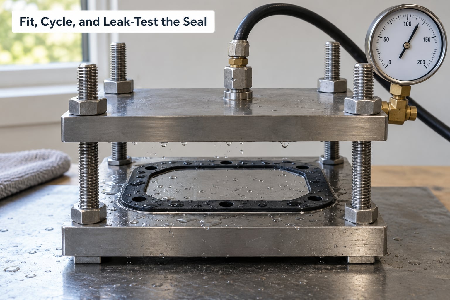
Set your limits before you trust any of this. A printed prototype is not automatically suitable for safety-critical, high-pressure, high-temperature, food-contact, medical, or certified sealing duties. If the joint fails and the failure mode is flooding, pressure or heat, a plastic seal is the wrong answer regardless of how well your test print performed.
Common Mistakes
Almost every leak traces back to one of the problems below, and almost all of them are fixable without changing your design.
Layer separation. Water tracks along a line where perimeters did not fuse. Print hotter within your filament’s range, slow down, drop the layer height, add perimeters, and make sure the outer perimeters are printing as a slow, continuous band. If the material has been sitting open, dry it first, because wet filament cannot bond properly no matter what temperature you use.
Under-compressed geometry. The part fits but never squashes, so it leaves a hairline gap. Reduce the groove depth or increase the seal thickness, then measure the compression marks. Too little compression leaks. Too much deforms the part permanently and shortens its life.
Weak first layer. A lift or peel on the first layer becomes a micro-gap running straight up through the seal. Clean the plate, raise the bed temperature, slow the first layer, and add a brim on a flexible material that will otherwise curl.
Support marks on the sealing face. Supports and their scars leave crescent-shaped leaks. Redesign to put supports on a non-sealing surface, use breakaway supports where they cannot be avoided, and inspect the face before fitting.
Wet filament. Popping, stringing, blobs and rough surfaces all trace back to moisture. Dry the spool properly, print from a dry box, and reseal the spool straight after.
Bowden kinks and clogs. Flexible filament buckles in the PTFE tube when it cannot keep up with retraction and fast travel. Lower or disable retraction, slow travel, raise the extruder above the spool so the filament feeds straight down, and consider a direct drive upgrade or a firmware pressure advance setting.
Compression set and swelling. Over-compression flattens the section permanently; exposure to oils, fuels or cleaners swells it and changes the fit. Match the material to the fluid, and check the seal again after a week of service rather than trusting day one.
Cracking under cycling. Thin cross-sections tear during installation or on the first few cycles. Thicken the section, round the corners more generously, and add lead-in chamfers so the part is not being forced into place.
Resin used where flexibility was needed. An under-cured resin print is brittle and will not seal. Wash and cure it fully, then treat it as a fit-check or mould only, since a rigid part cannot compress.
Before production, run one test part through the whole cycle and keep the record: material, dry time, printer, slicer settings, measured compression, and test results. Change one variable at a time. When something fails, most of the guesswork disappears within two or three tries.
Frequently Asked Questions
What is the best material for 3D printed gaskets and seals?
Polyether TPU is the usual answer for water, air and dust seals, because it is elastic, abrasion resistant and survives repeated compression. Polyester TPU is the better pick when the joint sees oils, grease or hydrocarbons, since it resists those fluids but slowly hydrolyses if moisture gets in. Polyether TPU 95A is the easiest to print, while 85A takes more squeeze for a tighter seal. Rigid filaments like PLA and PETG do not compress, so they only work as fit-check parts or moulds, never as seals themselves.
Can you print a waterproof gasket with TPU?
Yes. TPU makes a good waterproof gasket as long as every layer line is fully fused, because water follows any path between layers. Print hotter within your filament range, slow down, use four or more perimeters, keep infill low, and give the sealing face as few layer lines as possible by printing it flat. Dry the filament first, since wet TPU pops and blobs. Then test it: fill the joint partway, watch the seams, and hold it full and inverted to catch a slow drip.
Are resin 3D printers suitable for making functional seals?
Not for seals themselves. Resin prints are rigid and accurate, which makes them excellent for checking groove fit, testing clearance, and printing moulds for cast silicone. A rigid resin part cannot compress, so it will never create a seal on its own. Wash and cure it fully before using it as a mould, since an under-cured surface reproduces onto every casting. If the joint needs heat, oil resistance or long service life, print a mould and cast silicone rather than relying on the resin part.
How do I stop a 3D printed gasket from leaking between layers?
Increase layer adhesion first. Print within the upper part of your filament’s temperature range, slow the print speed, drop the layer height to around 0.15 mm and add perimeters so the outer band is dense. Print the sealing face flat in the XY plane to reduce the number of continuous paths a leak can follow, and print rings vase-style so there is no Z-seam notch. Finally, dry the filament: moisture is the most common reason flexible filament refuses to bond. Test with soapy water to find the exact path.
Can 3D printed seals replace molded rubber or commercial O-rings?
They can, for many low to moderate pressure jobs involving water, air, dust and vibration, and printed TPU seals are common repairs for appliances, plumbing, irrigation fittings and stepper motor dust covers. They should not replace molded rubber for automotive head gaskets, high-pressure hydraulics, fuel and oil service, food contact, medical use, or anything safety-critical, because the temperature ceiling and compression set of printed TPU fall short. For those, print a prototype and send the model to a rubber supplier.
Conclusion
Start by writing down the sealing conditions: gap, pressure or vacuum, temperature, fluid, movement and service life. Those numbers choose the material for you, and they tell you whether an extruded TPU print is even the right process or whether you should be casting silicone or ordering a molded part.
Then build the groove with compression in mind, aim for 15 to 25 percent squeeze as a starting point, print the sealing face flat, and give the part solid walls with dry filament. Print a small coupon before the real thing, measure it, and hold it under water or air before you trust it with anything you would mind losing.