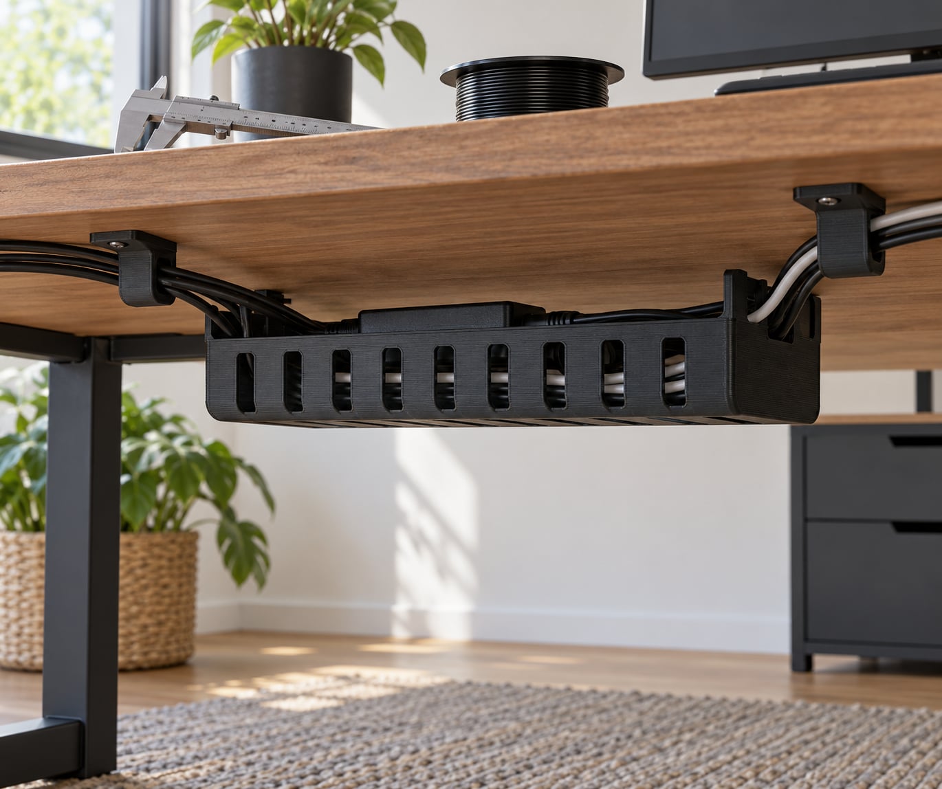
Cable management holders to print for a desk are small parts you download as STL or 3MF files and print yourself, so they match your cable diameter, your cable count, and the space under your desktop instead of a one-size tray from a store. Most people finish the first holder in an afternoon, and the only part of the job that really matters is measuring before you model.
The payoff shows up later. A power brick hanging off a connector by its own weight is the most common cause of cable trouble, and the fix is giving that weight somewhere to rest.
Table of Contents
- What You Need
- Step-by-Step
- 1. Measure the desk and map the cable routes
- 2. Choose a holder style for the desk
- 3. Design cable management holders to print for a desk
- 4. Export, slice, and test-print the holder
- 5. Check fit, strength, and cable retention
- 6. Install the finished cable holders
- Common Mistakes
- Frequently Asked Questions
- What is the best filament for 3D-printed cable management holders?
- Should I use PETG or PLA for an under-desk cable holder?
- What layer height and infill work best for strong cable holders?
- Can I print cable holders for any desk?
- Is it safe to use a 3D-printed holder for a power cable?
- Can I make cable holders without drilling into my desk?
- Conclusion
What You Need
The list is short, and most of it you already own. The two things worth buying before anything else are a decent pair of calipers and a length of PETG.
- Measuring tools: digital calipers, a steel ruler or tape measure, and a pencil for marking the underside of the desktop.
- CAD or modeling software: anything that exports STL or 3MF. Free options like Blender, FreeCAD, and Onshape cover this, and parametric customizers let you type a cable diameter into a form and get a ready file.
- A 3D printer: any FDM printer handles cable holders. There is no need for a resin machine, and nothing in this job needs a heated chamber.
- Filament: PETG for anything holding weight, PLA for light-duty clips, TPU 95A for flexible wraps. Keep a spool of each within reach if you own more than one printer.
- Fasteners: M3 or M4 machine screws with washers and nuts for screw-on mounts, and short wood screws with a pilot hole if you are going into a particleboard desktop.
- Optional adhesive: VHB foam tape or a two-part epoxy if the mounting surface is textured laminate. A thin liner of nylon or felt under any holder protects the finish.
Step-by-Step
1. Measure the desk and map the cable routes
Start with the underside of the desktop, because that is where most of the routing happens. Measure the depth from front edge to back edge, the width between the legs, and the clearance under the top once any drawer or crossbar is in place.
Then measure each cable at the thickest point, which is usually right at the connector. A USB-C cable is often 4 to 5 mm across including the jacket, and a braided HDMI cable can run noticeably thicker than the spec sheet suggests.
Leave yourself clearance for the connectors themselves. A cable does not stay in a channel if the plug is wider than the channel opening, and this is the single most common reason a printed holder looks fine on the printer and fails on the desk.
Mark the zones that stay clear. Monitor arm clamps, lifting columns on a standing desk, drawer runners, and modesty panels all move or occupy space, and a holder that intersects one of those is a holder you will reprint.
2. Choose a holder style for the desk
Five formats cover almost every desk, and each one solves a different problem.
An under-desk tray is the general answer. It screws to the bottom of the desktop, holds a power strip plus the slack from your cables, and keeps everything off the floor where it can be kicked. It is the format to choose when you have more cables than clips can handle.
A clamp-on holder grips the desk edge or a leg with no fasteners and no adhesive, which makes it right for rented desks, glass tops, and any surface you do not want to mark. The trade is that it adds bulk at the edge and can collide with a monitor arm clamp.
A cable saddle is a reusable clip you snap or slide over a bundle and screw or stick to a surface. It is the cheapest fix when cables follow one path along a leg or a wall, and printing a handful in a few sizes costs very little filament.
A multi-slot organizer separates cords into individual slots so they stay parallel instead of merging into one tangle. Choose it for monitor-arm cables, USB charging leads, and anywhere you want to unplug one cable without disturbing the rest.
A lightweight base or spool winder gives excess cable length somewhere to live. Excess length that has nowhere to go is what pulls on connectors, so if a cable is permanently straining, winding it up is the fix rather than tightening anything.
3. Design cable management holders to print for a desk
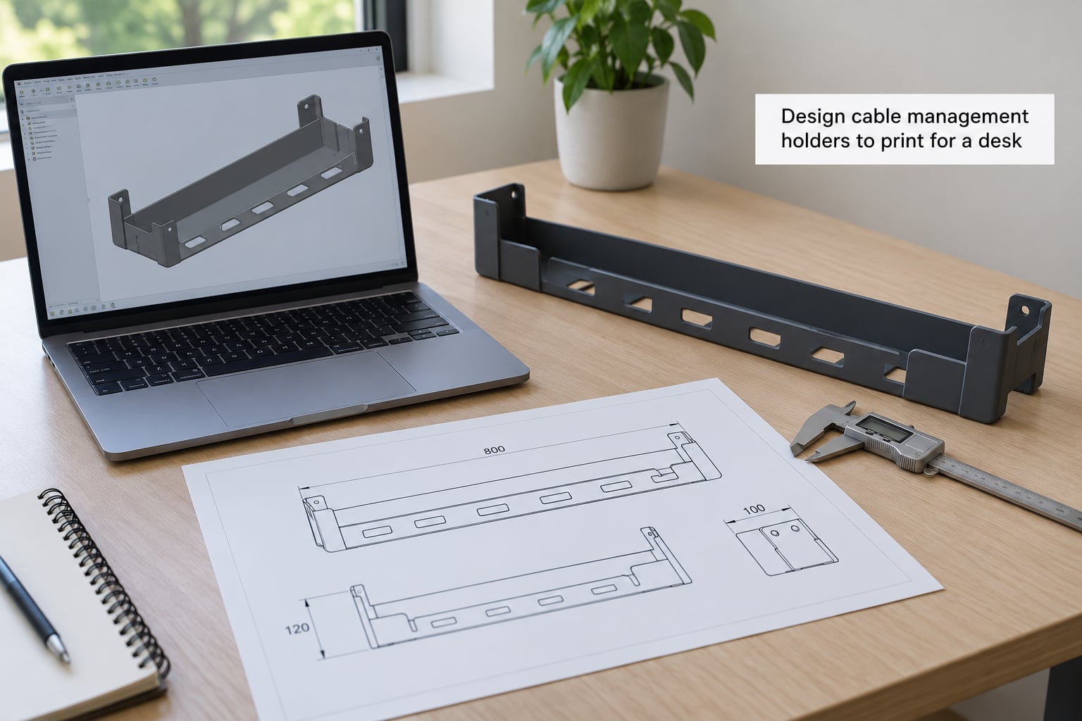
Converting measurements into a model comes down to a handful of numbers. Set the channel width to your largest measured cable diameter plus 1 mm for movement, and make the opening in the channel wall a little wider than that again so a jacket does not catch on the entry.
Give the holder real wall thickness. Three to four perimeters at 0.4 mm gives you roughly 1.2 to 1.6 mm of solid wall, which is the minimum that behaves like a part rather than a decoration. Anything thinner flexes when you press a cable into it.
Round every edge the cable touches. A 1 to 2 mm fillet on the channel entry removes the sharp lip that slices jackets over time, and it costs almost nothing to add in your slicer or your CAD tool.
Place mounting holes away from the load path. Put them along the wall that carries no cable force, leave a small countersink or recess for the screw head, and add washers on the back so the head does not dig into the desktop.
Model a breakaway support tab if part of the design needs bridging, and consider embossing a label on the face while you are in there. A raised ID3 or four-character code on a small saddle saves guessing later when eight identical clips are mounted under a desk in the dark.
If you would rather not model from scratch, open a parametric customizer and enter your cable count, cable diameter, and mounting style. These are common on the big model repositories, and they exist precisely because fixed-size STL files rarely match real cable gauges.
4. Export, slice, and test-print the holder
Export as STL for compatibility or 3MF when you want the slicer to carry your settings. Open the file in the slicer and check the mesh first: if it shows holes or overlapping surfaces, the CAD side needs a repair before you waste filament.
Orientation matters more than almost any other setting. Print channels and trays lying flat on the bed so each layer bridges a short, wide span, and print saddles with the channel opening facing upward. Printing a channel vertically puts the whole cable load across one line of perimeters.
Start with a 0.4 mm nozzle and 0.2 mm layer height, three to four walls, and 15 to 20 percent infill for clips and saddles. Bump walls to five or six for a tray carrying a power strip, where the load spreads across the whole part rather than a single point.
Enable a brim on larger footprints. A tray that rocks on the bed leaves a curled edge, and that curl is the first crack under load.
Supports are rarely needed for simple channels. When you do add them, keep the contact points small and set the slicer to build them from the bed so they break off cleanly, then ream the holes with a 4 mm bit afterward.
Print one corner or one saddle before committing to a full set. Ten minutes of test printing tells you whether the channel is right, and a badly sized holder printed forty times is a bad afternoon.
5. Check fit, strength, and cable retention
Test the printed part before you mount anything. The channel should accept your cable with a small amount of give, not a press fit, because cables are measured along their outside diameter and vary along their length.
Check the mounting surface with the part held in place. A screw-on tray needs flat, full-contact areas against the desktop; a clip sitting on a textured or slightly warped surface rocks, and rocking is what loosens screws over time.
Look for cracks radiating from mounting holes, white stress marks along layer lines under the channel, and any wall thinner than you designed. Flex it hard in both directions by hand. A part that flexes noticeably when you press a cable into it needs more walls before it goes anywhere near a desk.
Watch for interference with moving parts. Raise and lower a standing desk fully with the part loosely held in position, and swing a monitor arm through its range if one is present.
6. Install the finished cable holders
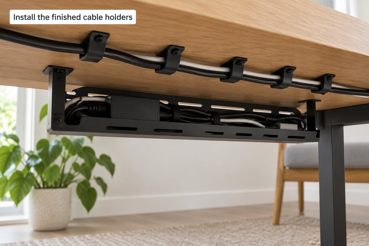
Install with the least intrusive method that actually holds. Clamps first, then adhesive, then screws. Screws into a particleboard desktop are the last resort, not the first choice, and they are the only option that permanently marks the surface.
When you do use screws, drill a pilot hole slightly smaller than the shank so the screw self-taps into the material, and add a washer on the inside face. Tighten until the head seats, then stop. Over-tightening a printed part splits the perimeter around the hole.
For adhesive mounts, clean both surfaces with isopropyl alcohol, score the laminate lightly with a file, and use a foam tape rather than a thin liner. Thin adhesive pads let go within weeks on textured surfaces; a mechanical anchor lasts years.
Never route a holder where it pinches a cable against a sharp desk edge, and never drill into a cable, a desk frame member carrying load, or anywhere near a mains power cable. Keep printed parts clear of power bricks that run hot, and never bundle a cable so tightly that heat has nowhere to go.
Common Mistakes
Nearly every reprint traces back to one of these.
Measuring the desktop instead of the cable. Channel width comes from the cable, not the desk. Fix: measure every cable at its connector and size the widest one first.
Channels sized exactly to the cable. A zero-clearance channel grips a cable instead of holding it, and grips it unevenly. Fix: add 1 mm of width and round the entry.
Weak mounting features. Thin posts around a screw hole crack under load. Fix: add a washer boss or a gusset and raise walls to five.
Support overuse. Heavy supports leave rough marks where they break off. Fix: reorient so the part needs fewer, and ream the holes.
Poor orientation. Printing a tray on its edge gives you thin walls across the load. Fix: lay it flat and rotate so layers bridge across the short span.
Visible layer lines in the channel. This is a finish issue, not a strength issue, but rough ridges abrade jackets. Fix: lower layer height to 0.16 mm on small parts or lightly sand the entry.
Adhesive as a permanent structural mount. Cheap adhesives detach under a loaded power strip. Fix: use a clamp or a screw, or accept that you will re-stick the part.
Undersized mounting hole positions. Screw heads dig into the desktop and preload the part. Fix: recess the head and fit a washer.
One more worth naming: PLA under a heavy power brick. PLA is fine for light clips, but a brick sitting on a PLA cradle long term can slowly sag, which is the complaint makers most often report about printed holders. Print that part in PETG.
Frequently Asked Questions
What is the best filament for 3D-printed cable management holders?
PETG is the best all-round choice for cable holders because it takes heat and weight without creeping. Use PLA for light clips and guides that carry no real load, and TPU 95A for flexible wraps or straps that need to stretch around a bundle. Avoid ABS unless you print in an enclosure, since it needs higher temperatures and warps without one.
Should I use PETG or PLA for an under-desk cable holder?
Choose PETG for an under-desk cable tray. A tray supports the weight of a power strip and slack cable for months at a time, and PETG keeps its shape under that sustained load while PLA can slowly sag. PLA remains fine for a small saddle or clip that only guides a cable and carries no weight. Match the filament to the load, not to the printer.
What layer height and infill work best for strong cable holders?
A 0.2 mm layer height with three to four walls and 15 to 20 percent infill covers most cable holders. Wall count matters more than infill here, because the load runs along the channel walls. Raise walls to five or six for a tray carrying a power strip, and drop the layer height to 0.16 mm only when you want a smoother channel edge.
Can I print cable holders for any desk?
Almost any desk, with a few checks first. Measure the clearance under the desktop, the cable diameters, and the space taken by a monitor arm clamp or a lifting column. Glass tops and some metal frames will not take screws, so use a clamp-on design there. L-shaped desks and desks with modesty panels need a shorter tray to clear the panel.
Is it safe to use a 3D-printed holder for a power cable?
Yes, as long as the holder routes the cable without pinching it, avoids a sharp edge, and stays clear of anything that runs hot. A printed part that carries weight is fine, and is often the safest place to rest a brick that would otherwise hang from its connector. Do not print a holder that squeezes a mains cable, and never drill into a cable to mount one.
Can I make cable holders without drilling into my desk?
Yes, and most desks should start that way. A clamp-on holder grips the desk edge or a leg with no fasteners at all, which is the best option for glass tops, rental desks, and any surface you do not want to mark. Adhesive mounts are the second choice. Reserve screws for a surface you own and are willing to drill, and always pilot drill first.
Conclusion
The fastest route to a tidy setup is boring and reliable. Measure the underside of the desk and every cable, print one small test piece, add walls wherever the first print flexed, and then install with the least intrusive mount that holds.
Leave the power cables themselves alone. No holder needs to modify a cord or a desk mechanism to do its job, and the whole point is to take the weight off a connector that has been carrying it for months.