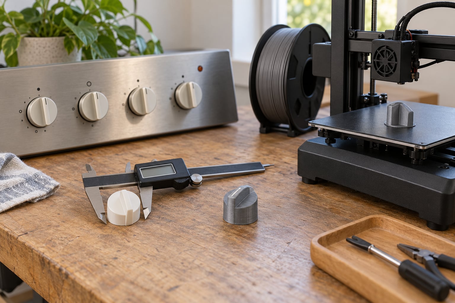
A knob is one of the cheapest parts on an appliance and one of the hardest to replace, because the original moulding is often discontinued or the shaft is a size nobody stocks. This guide walks through how to print a replacement knob for an appliance: measure the shaft, model a bore around it with the right clearance, print a small test coupon, then print the finished part. The whole job takes about an hour of work plus drying time, and the trickiest part is measurement, not printing.
Two things decide whether this works. The first is measuring your shaft accurately with digital calipers, including the flat on a D-shaped shaft. The second is choosing a material that survives where the knob lives, since a knob next to an oven burner behaves very differently from a washing machine selector.
For most readers the fastest route is not CAD at all. Searching Printables or Thingiverse for your appliance type turns up an existing model you can scale and edit in under ten minutes. The measuring and fitting steps below apply either way, so read them even if you never open a modelling program.
Table of Contents
- What You Need
- Step-by-Step
- 1. Measure the Original Knob and Appliance Opening
- 2. Choose a Practical Filament and Design Approach
- 3. Model or Adapt a Replacement Knob
- 4. Slice the Model for the Correct Fit
- 5. Print a Test Piece and Check the Fit
- 6. Print, Finish, and Install the Final Knob
- Common Mistakes
- Frequently Asked Questions
- Can you 3D print an appliance knob?
- What type of shaft does my appliance knob use?
- What filament should I use for an appliance knob?
- How tight should a 3D printed knob fit?
- Can I print a knob if the original one is missing?
- Is there anything illegal about printing a replacement part?
- Conclusion
What You Need
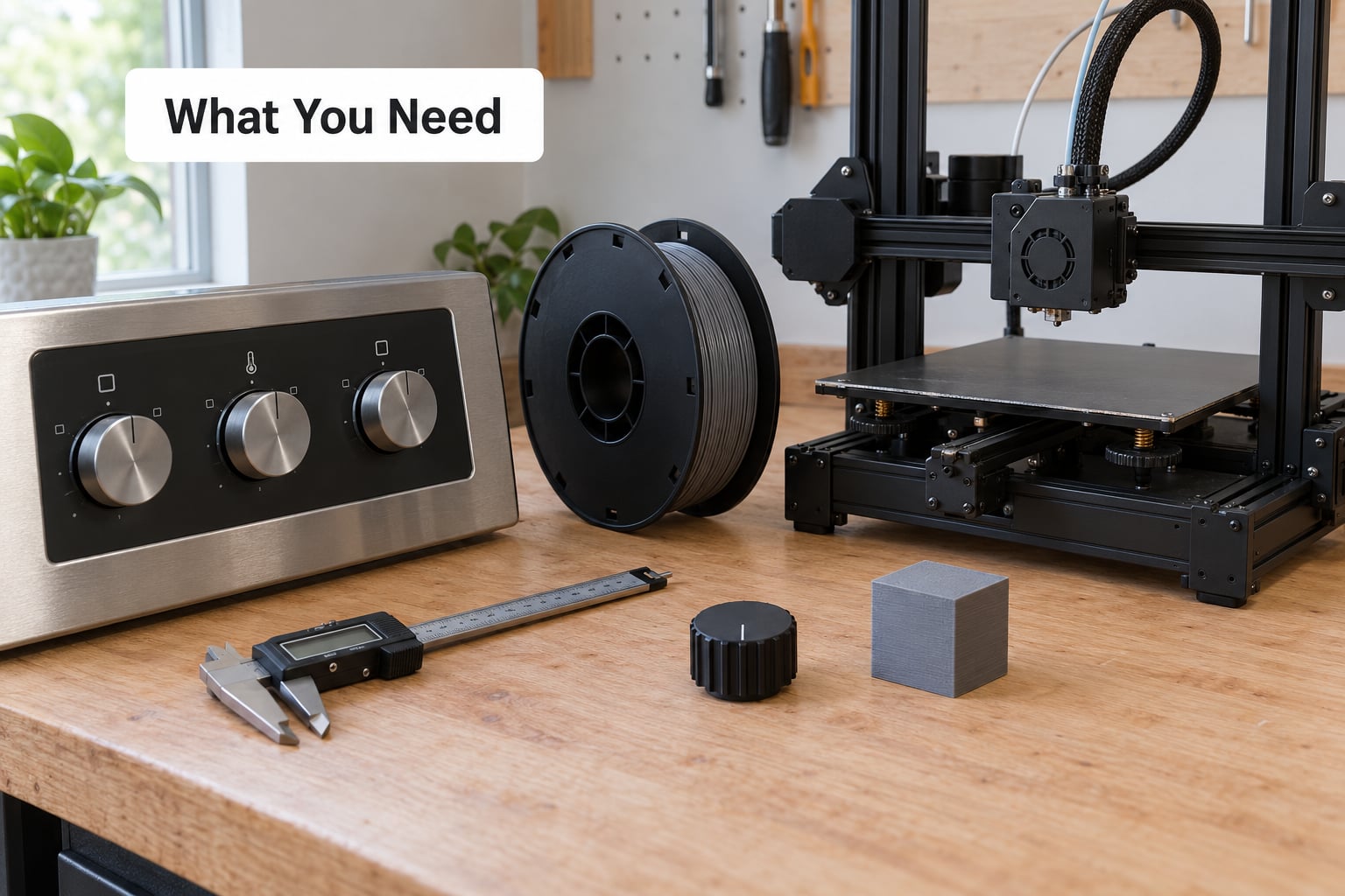
Start with the measurement kit rather than printer settings, because every dimension downstream comes from this list.
- Digital calipers with 0.1 mm resolution or better. A cheap Amazon caliper is fine for a 6 mm shaft.
- A ruler or depth gauge for the distance from the front panel to the point where the knob shoulder needs to stop.
- A 3D printer with a heated bed. An enclosure helps with ASA and ABS but is not required for PETG.
- Filament in the material you settled on in step two.
- Design software: a browser tool such as TinkerCAD for a first attempt, or FreeCAD, OpenSCAD or Fusion 360 once you want real parametric control.
- A parametric knob generator if you would rather set a diameter and a bore depth than draw geometry. Many of these run in OpenSCAD and generate a ready STL.
- Optional finishing kit: a small file or 220 grit paper to knock down the seam, a heat gun or lighter for heat-set inserts, and a small M3 grub screw if you want a mechanical lock.
- Safety gear: eye protection, gloves, and full disconnection of the appliance at the breaker before you touch a control shaft.
A 5 mm tall cylinder with nothing but the shaft bore costs about two grams of filament and ten minutes of print time. That is the cheapest insurance in the whole process, and I would not skip it on a shaft I have not measured before.
Step-by-Step
1. Measure the Original Knob and Appliance Opening
Four dimensions decide whether the replacement fits: shaft diameter, flat width, shaft length above the panel, and the diameter of the opening the knob has to clear.
Measure the shaft diameter across the round part with the calipers, then measure the flat width across the milled flat if the shaft is D-shaped. Write both down as separate numbers, because a 6 mm round shaft with a 5 mm flat is a very different bore from a plain 6 mm one. Measure twice and take the smaller reading if the two disagree.
Next, measure how far the shaft stands proud of the panel. That figure sets your bore depth. Leave about 1 mm less than the exposed shaft length so the knob bottoms out on the collar instead of riding down onto the shaft end, which makes it feel loose and can stress the internal potentiometer.
Then measure the opening diameter and the panel depth behind it, and check the knob clears whatever sits behind the panel. Note any pointer, a set screw hole in the panel, or moulded markings, and photograph the original knob from above and from the side while it is still fitted. If the knob is already gone, hold a ruler against the opening and check the appliance model number on the rating plate before you design anything.
2. Choose a Practical Filament and Design Approach
PLA is fine for a room-temperature control panel and wrong for anything near heat, since it softens noticeably around 55 C and can deform over a warm oven door.
| Material | Handles heat | Handles daily twisting | Notes |
|---|---|---|---|
| PLA | Poor, softens early | Good | Easiest to print, fine for washing machine and dishwasher selectors in a cool room |
| PETG | Fair | Excellent | My default for most knobs; tougher than PLA and sticks to the bed without an enclosure |
| ASA | Good | Good | Best for UV and heat, near an oven or on a laundry room wall with strong sun |
| ABS | Good | Fair | Warps badly without a heated enclosure, and fumes while printing |
| Nylon | Excellent | Excellent | Absorbs moisture and needs a dryer, but survives detergent and repeated use |
For a stove or oven control that sits near a hot zone I use ASA or nylon. For a washing machine program selector or a dehumidifier, PETG has never let me down. Whatever you choose, keep at least 4 walls and avoid thin, unsupported arms, because the failure mode is a finger breaking off the hub rather than the bore wearing out.
Design-wise you have three routes. Download an existing STL and edit the bore, run a parametric generator where you type in shaft diameter and depth, or model it yourself in CAD. The generator route is the fastest and the least error-prone for a first job.
3. Model or Adapt a Replacement Knob
Build the bore from your measured numbers, then add clearance in the right direction for the fit you want.
For a friction fit on a D-shaft, add 0.1 to 0.15 mm clearance per side. For a push-on press fit, go down to about 0.05 mm. If you are modelling a bore for a set screw to clamp in, make the round bore 0.3 to 0.4 mm larger than the shaft so the screw does all the holding.
Model the bore shape to match what you measured: a D-shape with the same flat width for a D-shaft, or a spline profile with matching tooth count and depth if it is splined. Add a chamfer at the mouth of the bore so the knob guides onto the shaft rather than catching on the first layer ridge, then add a pointer ridge or indicator line aligned to the panel marking. Three or four shallow finger ribs give far more grip than knurling does at this scale.
If you are adapting an existing model, scale is the usual trap. A Thingiverse stove knob model warns users that it may need printing at a different scale, and that warning is real: the bore is usually the only dimension that matters, so check it against your caliper reading rather than trusting the thumbnail.
4. Slice the Model for the Correct Fit
Slicer settings for a knob are about stiffness and hole accuracy, not surface detail.
- Layer height of 0.15 to 0.2 mm. Finer layers make the bore more accurate but the part stiffer and more likely to split along the layer line.
- Wall perimeters of 4 to 5, so the hub survives being gripped hard.
- Infill of 30 to 40 percent. Dense infill buys nothing here and makes the bore walls harder to clean.
- Orientation with the shaft cavity facing up. A bore printed on its side picks up layer texture on the inside and will not slide onto a shaft cleanly.
- Supports only if you print it bore-down. Bore-up usually needs none.
- Brim or raft when the footprint is small and wide, which is the usual knob shape, because a 40 mm disc lifts more easily than a 15 mm cube.
If you are printing on a printer with noticeable elephant foot, add 0.1 mm of extra clearance for the first 2 mm of the bore, or slice a small chamfer there. That single adjustment fixes most first-attempt tight fits.
5. Print a Test Piece and Check the Fit
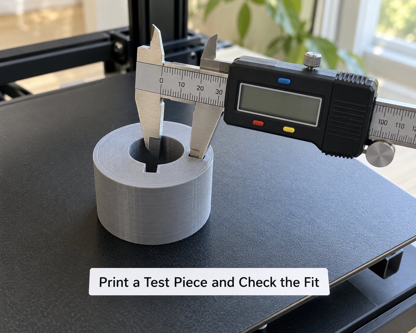
Print a coupon before you print the knob: a 5 mm tall disc with the same bore shape and the same clearance, nothing else.
Calipers across the hole tell you immediately whether your printer is running large or small. Push the coupon onto the shaft. It should go on with light hand pressure and turn with a firm but not forced grip, with no perceptible rock when you push it sideways.
If it will not enter, note how far it stops before you do anything else, because that distance is your per-layer error. If it drops on and spins, your bore is oversized or the shaft profile is wrong. Adjust the clearance in 0.1 mm steps and reprint the coupon, which costs less material than one failed full knob.
6. Print, Finish, and Install the Final Knob
Once the coupon fits, print the full part with the same orientation and settings you validated.
Break off supports at the mouth of the bore, then run a piece of 220 grit paper around the bore edge and across any seam line so the knob seats evenly. Measure the bore again after finishing. Heat-set a brass threaded insert into the side if you want a grub screw lock rather than a friction fit, and push an M3 screw down until it just contacts the flat on the shaft.
For the install, unplug the appliance or switch off its breaker, then push the knob on straight with a firm hand. It should seat by hand pressure, and if it needs force, stop and check the bore rather than forcing it onto the potentiometer. A thin PTFE tape wrap on the shaft is a legitimate temporary fix for a hole that ends up a fraction loose.
Restore power, turn the knob through its full range a few times, and confirm the setting on the display matches what the pointer points at. That last check catches a pointer offset that the fit test cannot.
Common Mistakes
Most failed knobs trace back to one of five things, and the first four are cheap to fix.
| What went wrong | Why it happened | Fix |
|---|---|---|
| Bore too tight, knob will not go on | No clearance added, or elephant foot at the bore mouth | Add 0.15 mm per side and chamfer the first 2 mm |
| Knob spins on the shaft | Bore oversized or round where the shaft is D-shaped | Model the flat, or wrap the shaft with PTFE tape while you reprint |
| Knob cracked near the hub | Too few walls, or thin arms with no infill behind them | Raise walls to 5 and thicken the hub to at least 4 mm |
| Knob deformed near an oven | PLA or PETG in a warm spot | Reprint in ASA or nylon |
| Part lifted off the bed mid-print | Small round footprint, poor adhesion | Add a brim and clean the bed with isopropyl alcohol first |
Before you call the job done, run through five checks: the bore measures within your target clearance, the knob turns without a wobble, the pointer lines up with the panel at two different settings, the hub shows no cracks under the printed ribs, and the appliance behaves normally at both ends of the control range. If the knob sits on a gas valve or a safety-critical heat control, replace it with the genuine part instead. A printed knob belongs on a control that fails safe when it slips, not one where slipping means unmitigated gas or an uncontrolled burner.
Frequently Asked Questions
Can you 3D print an appliance knob?
Yes, for most appliance knobs. Printed PETG, ASA and nylon parts handle the twisting, heat and detergent exposure these controls see. The limits are material and safety rather than legality: a knob on a washing machine selector or an oven timer is a fine print, while a gas valve control or a safety cut-off is not.
What type of shaft does my appliance knob use?
Most appliance shafts are D-shaped, meaning a round shaft with one milled flat that stops the knob rotating. Others are splined, round with a set screw, or a smooth push-on friction fit. Look at the shaft with a flashlight once the old knob is off, and measure the round diameter and the flat width separately with calipers.
What filament should I use for an appliance knob?
PETG for most indoor controls, ASA for anywhere near heat or strong sunlight, and nylon for parts exposed to detergent or moisture. PLA prints beautifully but softens around 55 C, which rules it out near an oven door or a warm laundry panel. Print a small coupon in your chosen material first so you test fit and temperature together.
How tight should a 3D printed knob fit?
For a friction fit on a D-shaft, leave 0.1 to 0.15 mm clearance per side. A press or push-on fit wants about 0.05 mm per side. If the knob is going to be held by an M3 grub screw, make the round bore 0.3 to 0.4 mm larger than the shaft so the screw does the locking instead of the plastic.
Can I print a knob if the original one is missing?
Yes. Measure the shaft directly with calipers, record the diameter, flat width and exposed length, and check the opening diameter behind the panel. Photograph the panel before you start, and look up the model number on the rating plate so you can search Printables or Thingiverse for an existing model built for that appliance.
Is there anything illegal about printing a replacement part?
Printing a knob for your own appliance is a personal-use repair and is not restricted. The real constraints are practical and legal in other senses: do not print parts that carry a safety certification, do not copy a branded design for resale, and check local rules if you plan to sell printed parts commercially.
Conclusion
Measure first, prototype second, print last. Put calipers on the shaft and record the diameter, the flat width and the exposed length, then spend ten minutes and two grams of filament on a 5 mm test coupon before committing to a full knob. Once that coupon slides on and turns without rocking, the rest is a straightforward print in PETG or ASA, and the appliance stops being dead weight over a cheap moulding.