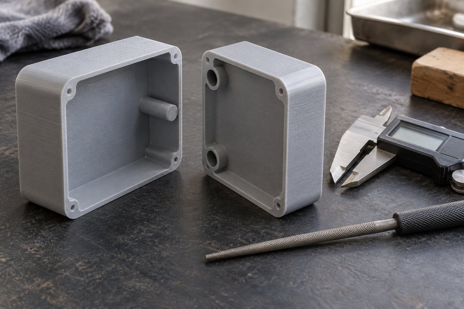
How to align split parts with dowel pins comes down to one idea: model a pin on one cut face and a matching socket on the other, so the two printed sections drop into the same position every time. The pin fixes the joint in all but one degree of freedom, and a flat mating face handles the rest. It takes about an hour of modelling for the pins alone, and the hard part is the tolerance, not the geometry.
Splitting a model is the right move whenever the part does not fit your build volume, prints better flat, or is easier to assemble in sections. The moment you split it, you inherit a flat butt joint, and flat butt joints slide. Glue and clamps alone will drift a few tenths of a millimetre and leave you with a seam gap that needs heavy filler. A dowel pin and socket take that drift away.
Here is the workflow I use, from the CAD file through to the glue-up.
Table of Contents
- What You Need
- Step-by-Step: How to Align Split Parts with Dowel Pins
- Design the Dowel Pin and Pocket With the Right Tolerance
- Mark the Mating Faces and Pin Locations
- Test Fit the Printed Parts
- How to Align Split Parts with Dowel Pins: Correct the Fit
- Common Mistakes
- Frequently Asked Questions
- What size dowel pin should I use for split 3D-printed parts?
- What clearance should a dowel-pin pocket have for FDM printing?
- How deep should a dowel-pin hole be in a 3D-printed part?
- Why are my dowel-pin holes too tight after printing?
- Can I use screws instead of dowel pins to align split parts?
- How do I keep the two printed halves from shifting during assembly?
- Conclusion
What You Need
A short list, and most makers already own four items on it.
- A CAD tool that can split a solid body. Fusion 360, Shapr3D, Onshape, FreeCAD, and SolidWorks all handle a split body with real solid geometry, which matters because you want to cut the pin and the hole from the same plane. If you only have a mesh file, an in-browser splitter such as Meshcast will cut the STL and add connectors, and PrusaSlicer, Cura, Bambu Studio, and OrcaSlicer can generate connector pins directly on the slice.
- Digital calipers. The cheapest tool here and the one that decides your fit. You need to measure the printed pin and the printed hole, not the numbers in your CAD file.
- A round file and a spare drill bit or reamer. One of them fixes a hole that is a fraction too tight. A 4 mm or 5 mm twist drill run by hand at low speed reams a printed socket without tearing the surrounding wall, and a round file takes the burr off the mouth afterwards.
- Filament for a fit-test coupon. A small plate with a pin and a hole at your real layer height and orientation. Make it from the same spool as the real parts, because PETG, PLA, and ABS each shrink differently.
- Cyanoacrylate or two-part epoxy, plus clamps. Thin superglue wicks into printed plastic and gives you a little working time. Epoxy is stronger and less brittle but needs longer to cure.
If your joint also has to carry a load rather than just sit in the right place, read the alternatives first. A dovetail, keyed slide, or tongue-and-groove handles shear better than two small round pins, and picking the wrong feature is the mistake people regret after the third reprint.
Step-by-Step: How to Align Split Parts with Dowel Pins
Eight stages: choose the split line, model the pin and hole together, set the clearance, print the pins on their side, print a coupon, dry fit, correct the fit, then bond and cure.
Design the Dowel Pin and Pocket With the Right Tolerance
Build the pin and its socket as a single pair of features cut from one split plane, not as two things you place by eye. In Fusion 360, sketch the pin and the hole on the same datum plane, offset the hole by your clearance value, then boolean both into the body before you split it. Do the same in Shapr3D or Onshape. Slicers that generate connector pins are faster but they sometimes render the pin and the hole at different diameters in the same model, which is exactly the inconsistent fit people complain about on the forums.
Now the numbers. Start with a pin diameter of 4 mm to 6 mm for most FDM parts, which is what traditional 6 mm hardwood dowels use and what survives printing. Make the socket 0.1 mm to 0.3 mm wider per side than the pin for FDM, so 0.2 mm to 0.6 mm wider in total. Resin printers hold tighter, around 0.3 mm total clearance versus 0.5 mm for FDM on a nominal snap fit. If a printed hole feels tight, the difference was almost always one of these.
Depth follows a simple rule: engage one to two times the pin diameter. A 5 mm pin wants 5 mm to 10 mm of engagement, which on a printed part usually means a blind hole with about 1 mm of solid floor left behind. Cut a lead-in chamfer of 0.5 mm to 1 mm at the mouth of the socket so the hole finds the pin instead of fighting it, and add a small fillet where the pin meets the face so you do not start a crack.
For context on how tight this is: a CNC-machined press-fit dowel hole is reamed to about 0.025 mm of tolerance. Your FDM socket will never hold that, so never design a joint that depends on interference to stay together. Use clearance for location and glue for strength.
Mark the Mating Faces and Pin Locations
Identify the real mating surface before placing any pin. The face has to be flat and continuous across the whole joint, not a curved or stepped region that only touches in one spot. If the split plane cuts across a rounded surface, trim it flat or add a thin registration pad so both halves have something solid to seat against.
Keep the cut plane coplanar in CAD. After a split, mirror the pin locations across the split plane rather than measuring and re-entering them, and confirm both sockets use the same construction plane. A hair of angular error in the CAD file shows up as a visibly crooked joint no matter how good the pin fit is.
How many pins you need comes down to degrees of freedom. One pin leaves rotation and tilt completely free. Two pins fix everything except spinning about the line running between them. A third pin removes that last freedom, which makes three the practical minimum for anything that must not rotate, and four corners is the right answer for a large flat panel that will get handled.
Spread the pins as far apart as you can. Two pins eight centimetres apart control angle far better than two pins two centimetres apart, because angular error scales with the length of the baseline. Push them away from sharp corners where the socket would break out, and keep them clear of the visible seam line if appearance matters. When rotation still gets past you, swap one round pin for a square or D-shaped one. Round pins let a part index in any rotation, and that is sometimes exactly what you want.
Test Fit the Printed Parts
Print the coupon before the real parts, not after. Same filament, same layer height, same orientation, and put the pin in the orientation it will actually use. A pin printed flat has an elephant’s foot on its first layer and a hole printed flat has the same problem in reverse, and both show up in a coupon that costs a few grams of filament.
Measure both features with the calipers and write the numbers down. Then dry fit with light hand pressure only. If you need a tool to push the pin in, the fit is wrong and it will not improve as you print more parts. Look at the seam with a light behind it: an even hairline means the pin is doing its job, a wedge-shaped gap means one socket is off-axis.
Some makers deliberately model only the female features on both halves and print the pins as separate parts, so a snapped pin is a two-minute reprint instead of a four-hour one. That is a sensible habit on any joint you are not yet confident in.
How to Align Split Parts with Dowel Pins: Correct the Fit
A tight socket is the common failure and it has a proper fix. Put the drill bit or reamer in a hand drill, or just use the twist bit in a pin vice, and rotate it slowly by hand with light pressure. You are cutting the printed hole to size, exactly like a machinist reams a dowel hole rather than drilling it to nominal. Take a measurement every few strokes and stop when the pin slides in with a small amount of friction. Twenty gentle seconds beats twenty minutes of heating the part with a lighter, which softens the surface and makes the hole oval.
A loose socket cannot be reamed. Shrink the modelled hole by 0.1 mm per side, print another coupon, and repeat. For a permanent repair, run a thin bead of epoxy around the pin before assembly and clamp it, or fit a slightly oversize printed sleeve over the pin.
When the pin itself is the problem, the cause is usually in the slicing, not the model. An oval or rounded pin comes from the first layer squashing the footprint or from elephant’s foot, and it shows up as wobble even when the diameter is right. Fix it by scaling XY compensation down, lowering the first layer, or lightly sanding the pin. A pin that snapped at the root was printed vertically, and vertical printed pins have terrible layer adhesion. Lay the pin along the bed instead, even if that means the surrounding face does too, or print the pins as separate flat parts.
If the parts are crooked rather than loose, stop and check the split plane before touching a drill. Two half-millimetre errors in opposite directions cannot be fixed by reaming. Re-cut the plane, mirror the pin locations properly, and reprint the half with the wrong sockets.
Clamping deserves its own warning. Thin printed walls bow under pressure and push the part out of alignment, which undoes everything the pin just did. Use wide cauls, clamp over the pins rather than beside them, or tape the joint and let it cure with light pressure from a rubber band.
Common Mistakes
These are the errors that come up over and over in print forums, and every one has a cheap fix.
- Measuring from the same edge twice. When you lay both halves down to mark pin locations, you almost always mirror one of them by mistake. Mark in CAD against a shared plane instead, never on the print bed.
- Guessing the socket diameter. Several makers on r/3Dprinting report measuring 0.1 mm larger in X and Y than the mating pin as the fix for a joint that would not go together. Measure, do not guess, and print the coupon.
- Printing pins vertically. A pin standing on end snaps at its root the first time you push two halves together. Print it flat.
- Trusting the slicer’s cut feature blindly. Connector-pin tools can produce a pin and a hole at different nominal sizes. Dry fit before you run the whole set.
- Relying on glue to hold a joint that does not align. If the halves slide, the seam opens while the adhesive cures and the part ends up permanently crooked.
- Drilling printed holes to nominal size. Traditional dowel practice from the machining and woodworking forums is to ream, not drill, and it transfers directly to plastic. A drill bit at full speed melt-exits and leaves a bell-shaped hole.
- Oversizing the socket to make assembly easy. A hole 1 mm loose will not be rescued by glue. Fix the geometry instead.
- Using only one pin on a large panel. One pin leaves the whole joint free to spin and tilt, which looks like a fit failure but is really a design error.
- Skipping the coupon because the parts are small. Every printer and every material differs, and there is no universal clearance value. The coupon decides it, not a forum post.
Two more habits worth keeping. Print the pins as a separate part so they can be replaced, and try a 0.12 mm layer height for a tighter fit when your printer can hold it, as people on r/3Dprinting report. Some Bambu Lab users model 5 mm guide holes in both halves and print the pins separately with light supports, which gives the cleanest fit of anything I have tried.
If the joint is load-bearing, change the feature rather than the tolerance. Dowels locate; they are poor at holding shear. Once you have assembled it dry and it still twists under hand pressure, a dovetail or keyed rail is the fix.
Frequently Asked Questions
What size dowel pin should I use for split 3D-printed parts?
Start at 4 mm or 5 mm in diameter for most FDM split parts. That matches common hardwood dowel sizes and is stiff enough to resist snapping while still fitting a printed socket. Print it flat on the bed rather than on end, and keep the engagement between one and two times the pin diameter. Buy a 6 mm wooden dowel instead if you want a repeatable fit you can re-drill later.
What clearance should a dowel-pin pocket have for FDM printing?
Make the socket 0.1 mm to 0.3 mm wider per side than the pin, so 0.2 mm to 0.6 mm wider in total. FDM holes come out slightly undersize because of extrusion width, and resin printers can be held tighter, around 0.3 mm total. State per-side or total whenever you give a number, because a guide that says 0.3 mm without saying which one is useless.
How deep should a dowel-pin hole be in a 3D-printed part?
Aim for one to two times the pin diameter, so a 5 mm pin engages 5 to 10 mm deep. Leave about 1 mm of solid material at the bottom so the blind hole does not punch through the face. Add a 0.5 mm to 1 mm chamfer at the mouth. Deeper than twice the diameter adds print time and weight without improving the fit.
Why are my dowel-pin holes too tight after printing?
Three usual causes: the socket was modelled at nominal size with no clearance, the first layer of the socket printed slightly small, or the pin picked up elephant’s foot and grew at its base. The fix is to ream the printed hole by hand with a drill bit or round file, turning slowly and checking with calipers until the pin slides in with light friction. Never use heat, it makes the hole oval.
Can I use screws instead of dowel pins to align split parts?
Yes, and it is often the better choice on a heavy or repeatedly handled part. Screws locate and clamp in one operation, but they need printed bosses, a pilot hole, and enough wall thickness, which adds weight and print time. Dowel pins are cheaper to model and let the seam stay flush. Many makers use dowels for location and a couple of screws only where extra clamping is needed.
How do I keep the two printed halves from shifting during assembly?
Push the pins home fully before you apply any adhesive, then clamp over the joint rather than beside it. Use wide cauls or a scrap plate so pressure spreads instead of denting thin printed walls. If a half still creeps, tape it and leave light pressure from a rubber band while the adhesive cures. A drop of cyanoacrylate on each pin locks the two halves as one rigid body in seconds.
Conclusion
Start with the first action, not the assembly: model the pin and the socket as a matched pair on one split plane, give the socket 0.1 mm to 0.3 mm clearance per side, and print a coupon before you run the real parts. Three pins placed as far apart as the part allows will fix everything except spinning. Measure what actually comes off the bed, ream what is tight, and your seam will close on the first glue-up instead of the fourth.