MeshLab is a free, open-source program for cleaning, repairing, scaling, and simplifying 3D meshes so they come out of your workflow as a watertight STL your slicer can handle. The meshlab basics for preparing printable models come down to six moves: import, inspect, clean, repair, orient, export. The first pass on a fresh model takes about fifteen minutes; the fiddly part is knowing which repair filter to run and when to stop.
Here is the honest version. MeshLab is a mesh editor, not a modeling program, so it will not fix a design that is wrong in the first place. It is very good at taking a scan, a boolean result, or a downloaded file that arrived broken and making it slice cleanly. Everything below assumes the free current build of MeshLab on Windows, macOS, or Linux, and a slicer such as Cura or PrusaSlicer already installed.
Table of Contents
- What You Need
- Step-by-Step
- 1. Import the Mesh and Check Its Scale
- 2. Inspect and Clean the Geometry
- 3. Repair Holes, Non-Manifold Edges, and Degenerate Faces
- 4. Check and Improve Mesh Quality
- 5. Orient and Position the Model
- 6. Export a Production STL
- Common Mistakes
- Frequently Asked Questions
- Do I need to convert the mesh in MeshLab before exporting an STL?
- Should I use binary or ASCII STL for 3D printing?
- Why does my repaired mesh still show errors in the slicer?
- Are STL files measured in millimeters or inches?
- Can MeshLab make a scanned model printable without CAD software?
- When should I use MeshLab’s simplify filter?
- Conclusion
What You Need
You need very little. A desktop machine running MeshLab, the mesh you want to fix, and a slicer to test the result in. That is genuinely the whole list.
- A desktop computer. MeshLab is a desktop application. There is no phone or browser version, and a laptop is fine for models up to a few million faces.
- MeshLab for Windows, macOS, or Linux. It is free and open source, and the same build runs on all three. Install it from the official site rather than a bundled copy inside a scanner package.
- A source mesh in STL, OBJ, PLY, or another supported format. Scans usually arrive as point clouds in PLY or XYZ, which MeshLab can open too.
- A slicer such as Cura or PrusaSlicer. This is your verification tool. Every fix gets confirmed by loading the exported STL into the slicer and seeing whether the error list goes quiet.
- Optional reference measurements. A caliper, a known reference object, or a real dimension from the original part. This matters for scans, which often arrive at the wrong real-world size.
- Optional CAD tools. FreeCAD or Meshmixer, for the cases where the mesh is fine but the geometry is not.
One practical note before you start. Menu names shift slightly between MeshLab versions, so if a filter is not exactly where this says it is, use the search box in the top right corner of the Filters menu and type two or three words of the filter name. It finds filters faster than scrolling does.
Step-by-Step
1. Import the Mesh and Check Its Scale
Open MeshLab, use File and Import, and pick your file. Before touching anything else, look at the model and then measure it. Tools and the Measure panel let you check the bounding box, and that number tells you whether your slicer is about to misunderstand the file.
STL stores no units. It is just coordinates. A slicer reads those coordinates as millimetres, so a model exported from a program using inches will arrive scaled twenty-five times too large, and a model exported in a different unit can arrive microscopic. Visual size on screen tells you nothing, which is the trap most beginners fall into.
Use the Measure tool to click two points you know the real distance between, or read the bounding box dimensions against something familiar. Say the part should be 120 mm long and the bounding box says 3048. That is 120 inches, a file that came from a CAD package working in inches. Divide by 25.4 to get millimetres. Do the maths once here rather than guessing later in the slicer scale settings, where a mistake is far easier to miss.
How do you tell whether it worked? The bounding box now matches the real measurement, and the model no longer looks absurd next to a millimetre grid in the viewport.
2. Inspect and Clean the Geometry
Clean the geometry before repairing it, because a repair filter will happily work hard to fix a defect you should have deleted. Zoom all the way in and orbit around the model. What you are looking for is anything that is not part of the part.
Common finds: duplicate faces sitting exactly on top of each other, loose vertices floating near the surface, small isolated chunks of geometry left over from a scan, and speckles of noise around the edges. Scans are the worst offenders here, because a single pass of a scanner picks up the table it was sitting on and a bit of your sleeve.
Use the selection tools to click a bad component, then use Filters and Cleaning and Repairing and Remove Isolated Components with a face-count threshold low enough to catch specks but high enough to leave genuine small features. A useful starting threshold is a few hundred faces. If a real part of the model is small, select and keep it deliberately rather than trusting the threshold.
What to keep versus what to delete comes down to intent. A figurine with a separate detachable base is two components on purpose, and merging or deleting pieces will break it. Scan noise never is. If you are unsure, hide the layer rather than deleting it, and turn layer visibility back on to check the result from every angle.
3. Repair Holes, Non-Manifold Edges, and Degenerate Faces
This is the step that turns a broken mesh into a printable one, and the reason most people search for meshlab repair mesh tutorials. Head to Filters and then Cleaning and Repairing. There are about a dozen filters in there; you probably need four or five.
- Remove Zero Area Faces gets rid of slivers and degenerate triangles, which confuse slicers and inflate the face count.
- Remove Duplicate Points followed by Remove Duplicate Faces clears overlapping surfaces from boolean operations and scan merges.
- Close Holes fills small openings. Set the maximum hole size low, start around ten to twenty, and raise it only if a specific gap stays open.
- Repair Non Manifold Edges by Removing Faces cleans up edges shared by more than two faces, which is the single most common reason a slicer complains.
- Merge Close Vertices snaps near-coincident vertices together so a surface that was split reads as one continuous shell.
Automatic repair is powerful and slightly dangerous, so work in a careful order. Closing holes at a large size swallows thin features. A wall thinner than your hole setting simply disappears, and you will not notice until the print comes out missing a piece.
Run one filter, look at the model, then run the next. Filters in MeshLab are destructive and most of them cannot be undone, so the only real recovery is re-importing. This is why the safe rule is simple: keep the original file untouched, and save your working version under a new name before the first filter.
Cuts and thin internal cavities are the two cases where repair does more harm than good. A model with a deliberate hole through the middle is not broken, and closing it changes the part. A shell with a wall thinner than the Close Holes threshold will be patched into a solid lump. Both are easier to avoid than to undo, so inspect with the wireframe view on before running anything automatic.
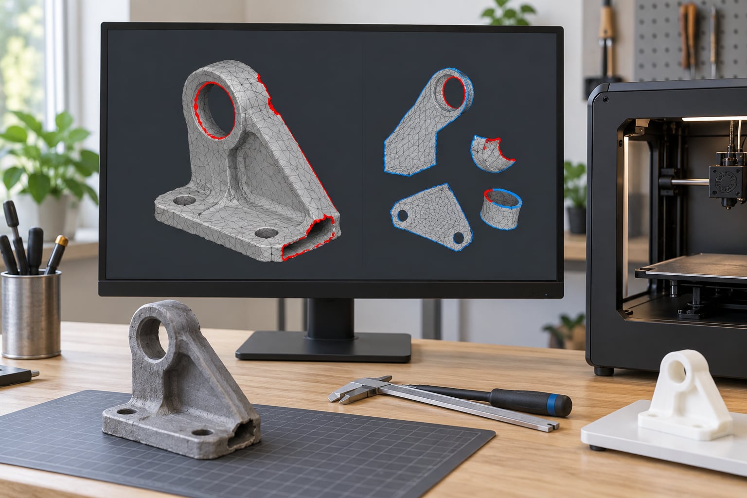
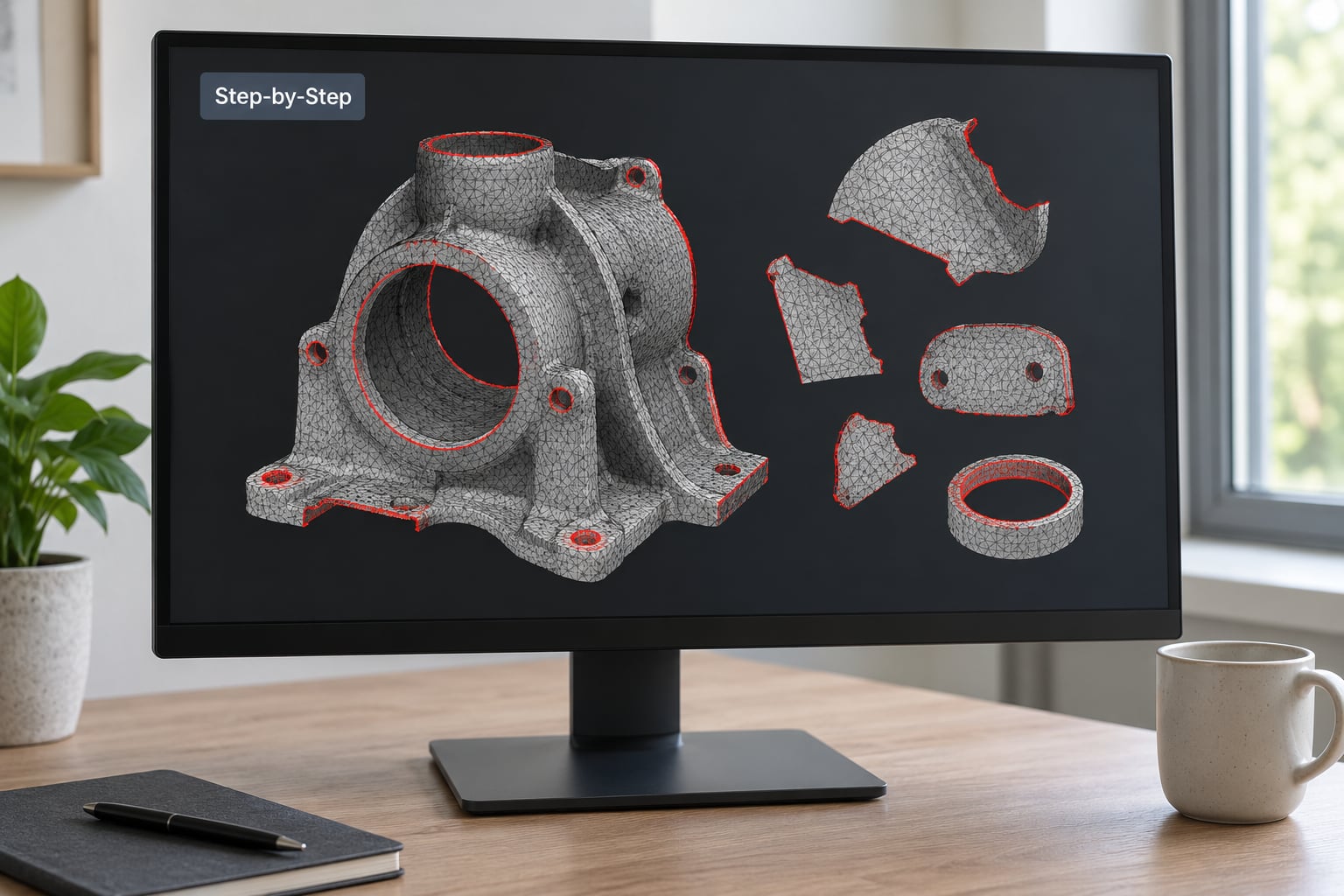
How do you know a repair worked? Turn on face inspector, click around, and look for the red-highlighted non-manifold and boundary edges. The list should be empty or down to a handful you deliberately chose to keep.
4. Check and Improve Mesh Quality
Once the mesh is clean, look at the face count in the status bar. A scanned part can easily land above a million triangles, which is fine for your own printer and a hard limit at most print services. Reducing it is not always necessary, so only do it when the number is actually a problem.
The filter for this is Filters, then Remeshing, Simplification, and Reconstruction, then Simplification: Quadric Edge Collapse Decimation. Set the target number of faces to what you need, which is often a quarter or a half of what you have. Turn on the preserve topology option, then apply. The result is the same shape with a fraction of the geometry.
Simplify selectively. A decimation pass across a whole model smooths off exactly the detail that makes it worth printing, such as fine ribs, threads, and engraved text. One Fab Academy student ran surface reconstruction on a 110 MB scan and brought it only to 100 MB, which is a fair warning that geometry-heavy files need more than one tool.
Smoothing has the same trap. Applying a Laplacian or Taubin smoothing filter to an entire model rounds off every sharp edge you spent hours modelling, and on a printed part, sharp edges are the difference between a part that fits and one that does not. Smooth scan noise in small selections, not the whole model.
A useful last check is self-intersections. Run the analysis under Filters and Cleaning and Repairing, and remove them if there are any, because the slicer cannot resolve a surface that passes through itself. Then remember the honest limit: a watertight mesh is a closed shell, not a strong one. Thin walls stay thin. If a wall is under about 1 mm on an FDM printer, you have a strength problem no filter will solve.
5. Orient and Position the Model
MeshLab will not decide your print orientation, but getting the model sensible before export saves you rearranging it later. Rotate the part so it sits the way you want to slice it, flat on the build plate, with the largest broad face downward. Lay a bracket or a phone-case style part on its big flat side and it prints in far fewer layers with less support than standing on edge.
The distinction to keep clear is editing orientation versus print orientation. In MeshLab you are positioning the model in its own coordinate space. In the slicer you choose the print orientation, and the slicer wins. Use MeshLab for the obvious stuff, like turning a model that came in on its side and a part that floats above the origin, then confirm and adjust in the slicer.
If the part rocks, the answer is not rotation. It is a flat base, and MeshLab can help you cut one with a plane or box operation, though Meshmixer does this more comfortably. If you hit that point often, that is a good sign to move the job rather than fight the tool.
6. Export a Production STL
Use File and Export Mesh as STL. You get a binary or ASCII choice, and you should pick binary for anything you intend to print or upload. Binary STL is the same geometry in a fraction of the file size, and every slicer reads it. ASCII is readable, which is occasionally useful for debugging, but it is the wrong default for a production file.
Name the file for the version, not the model. part-bracket-v2-stl is the kind of name that saves you an afternoon six weeks later. Check the units dropdown if one appears, confirm the scale reads in millimetres, and export.
Then do the step that separates people who export files from people who print them. Load the exported STL into your slicer and check four things: the size matches your intent, the orientation is what you expected, the error list is empty, and the layer preview looks right. If the slicer still flags something, go back to step 3 and read the actual error message rather than re-running every filter blind.
Common Mistakes
- Repairing the only copy. Filters are destructive. Import, immediately save a working copy under a new name, and keep the original untouched.
- Running all the repair filters at maximum settings. A Close Holes size of 100 on a part with 0.8 mm ribs will fill them in solid. Start small.
- Smoothing the whole model. You will round off every edge. Smooth selections, and only the scan noise inside them.
- Guessing at scale. Measure against a real reference and do the unit conversion properly rather than typing an arbitrary number into the slicer.
- Exporting with mismatched units. STL carries no unit data. The number in the export dialog is the only chance to get it right.
- Leaving support geometry inside the shell. A single imported model is cleanest. If you merged parts, check the interior for stray shells before exporting.
- Trusting a watertight check on its own. Watertight means closed, not printable. A real test slice in Cura or PrusaSlicer is the only real verdict.
Frequently Asked Questions
Do I need to convert the mesh in MeshLab before exporting an STL?
No. MeshLab reads STL, OBJ, PLY, and point cloud files directly, and it writes STL directly. The work that matters is repairing and cleaning the geometry, not converting between formats. Convert only if your slicer genuinely refuses a format, which is rare, since every slicer reads STL.
Should I use binary or ASCII STL for 3D printing?
Use binary STL for anything you plan to print, upload to a print service, or email. It holds the same geometry in a much smaller file, and every slicer reads it. ASCII STL is plain text, which makes it useful for inspecting a file in a text editor or debugging a strange model, but it is the wrong choice for production.
Why does my repaired mesh still show errors in the slicer?
Usually one of three things. The repair ran at too low a threshold, so the defect is still there. The filter fixed the outside and left an internal shell or a self-intersection. Or you exported a different copy than the one you repaired. Reimport, re-check the face inspector, and match the error text to the specific filter rather than re-running everything.
Are STL files measured in millimeters or inches?
Neither. STL stores raw coordinates with no unit information at all, so the same file can be interpreted as millimetres or inches depending on who reads it. Every slicer assumes millimetres. That is why a model exported from CAD software using inches prints twenty-five times too large, and why you should verify the bounding box in MeshLab before exporting.
Can MeshLab make a scanned model printable without CAD software?
Yes, for most scans. Close small holes, remove isolated noise, merge close vertices, decimate, and export as STL. What it cannot do is add missing geometry or thicken a fragile wall, and very heavy scans may need several passes. If the scan has a whole missing region rather than small holes, you need to fill that gap in CAD or Meshmixer first.
When should I use MeshLab’s simplify filter?
Use it when the face count is a real constraint, such as a print service that caps files at one million triangles, or when your machine struggles to slice a dense mesh. Skip it when the model is already under the limit, because every pass removes fine detail such as threads, ribs, and engraved text that you will not get back.
Conclusion
Start by importing the model and checking the bounding box against a real measurement. That single check catches the most common failure in the whole workflow, and it takes about a minute.
From there the order holds every time: clean the geometry, repair only the defects you can see, simplify if the face count is actually a problem, orient the part, export binary STL, and open the result in your slicer. That is the whole of meshlab basics for preparing printable models, and it is enough to turn most scans, boolean results, and free downloads into files that slice without complaints.
Slice it, preview the layers, and run one small test print before committing to a long job. A ten-minute test that comes off the plate cleanly tells you far more than an hour of staring at the model.