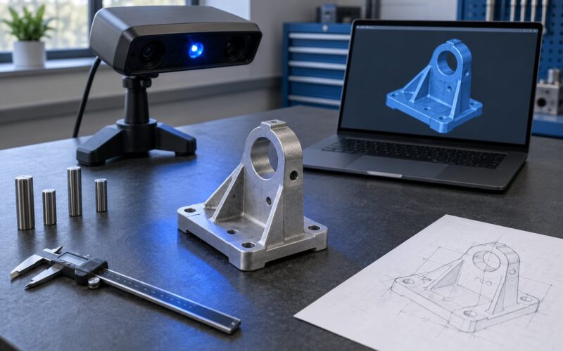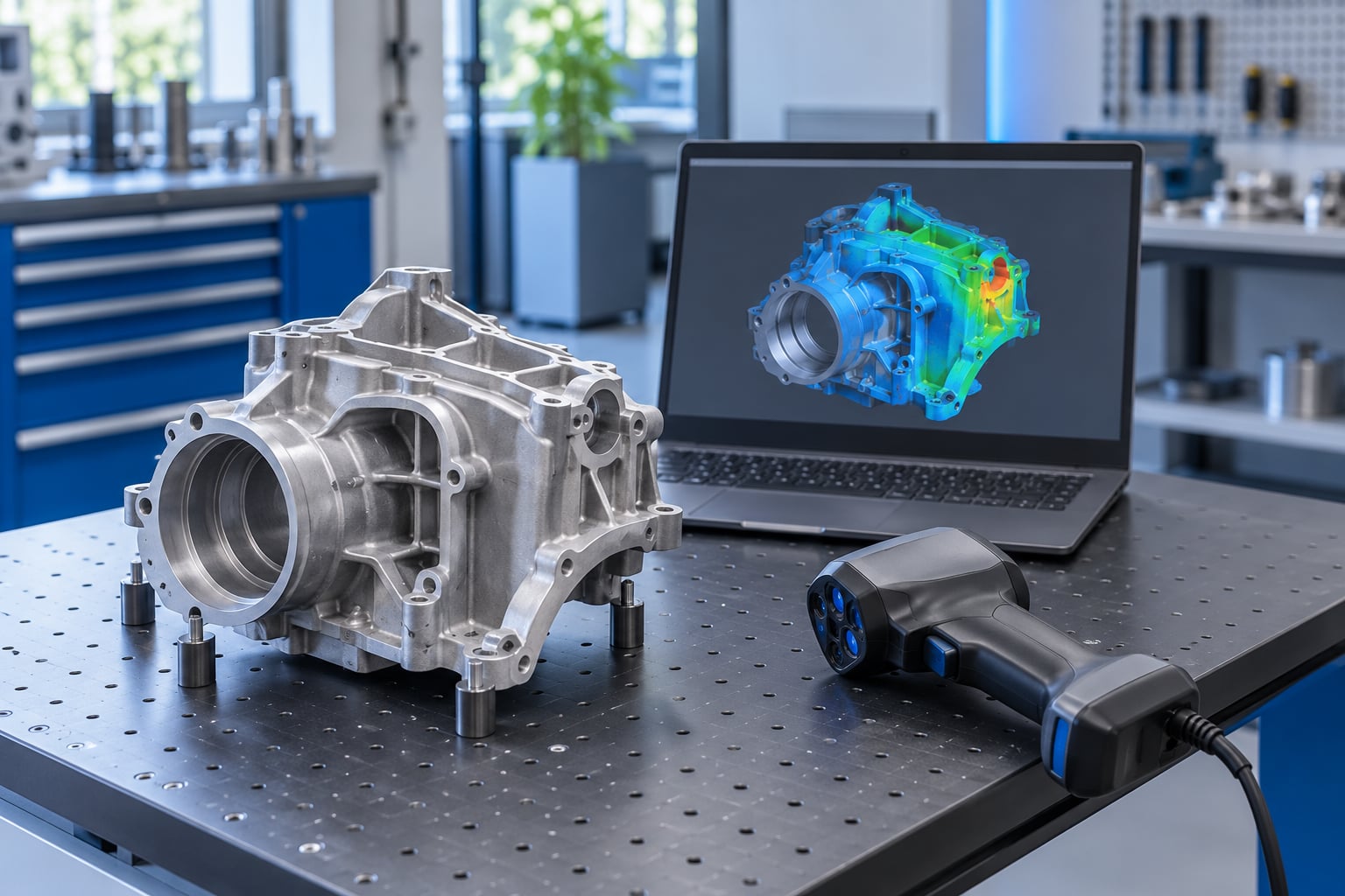
3D scanning for quality inspection is a non-contact way to check a part: a scanner captures its entire surface as a dense point cloud, then inspection software measures every point against the CAD model to show where the real part deviates from the design. It is fast, repeatable and handles geometry that is awkward to touch with a probe, which is why shops lean on it for first article inspection, freeform surfaces and process diagnosis. Here is how the technique works, how accurate the result has to be, and where it beats a coordinate measuring machine.
Table of Contents
- What Is 3D Scanning for Quality Inspection?
- What 3D scanning measures that visual inspection misses
- How it differs from a coordinate measuring machine
- How Does 3D Scanning for Quality Inspection Work?
- Which 3D Scanning Methods Are Used for Quality Inspection?
- How Accurate Does a Quality Inspection Scan Need to Be?
- How Do You Inspect a Part Against Its CAD Model?
- How 3D scanning for quality inspection compares a scan to CAD
- What Are the Main Challenges in 3D Scan-Based Inspection?
- When Is 3D Scanning Better Than Other Inspection Methods?
- How Can You Build a Reliable 3D Inspection Process?
- Frequently Asked Questions
- How accurate are 3D scanners for quality inspection?
- Can 3D scanning replace a CMM?
- How do you scan shiny or chrome parts?
- Is calibration required for 3D scanners?
- What are the main types of 3D scanning technology?
- How long does a scan-to-CAD inspection take?
- Conclusion
What Is 3D Scanning for Quality Inspection?
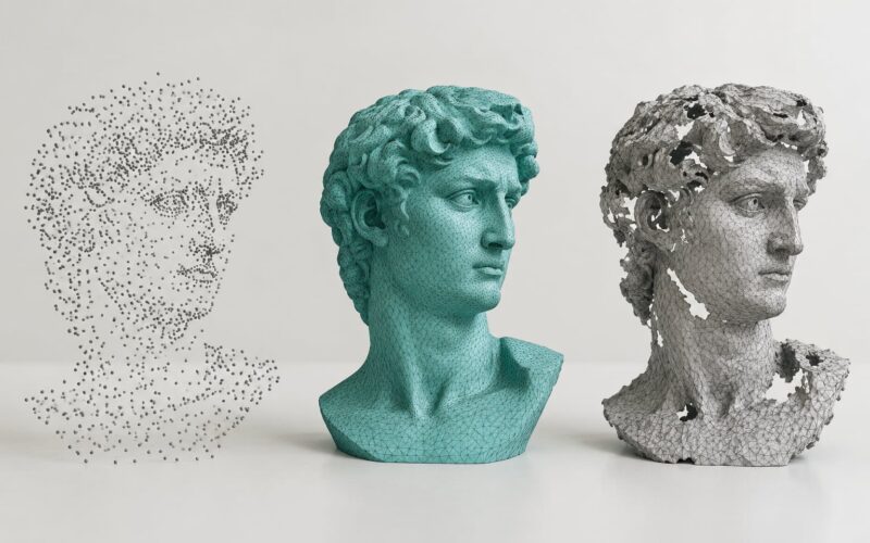
3D scanning for quality inspection is a measurement technique that captures the physical shape of a part as millions of XYZ coordinates, then compares that point cloud to the nominal CAD model. The output is a deviation map: every scanned point is colour-coded by how far it sits from the intended surface, so you see the whole part at once instead of a list of isolated numbers.
Two things get measured, and they are worth separating. Geometry is the shape itself — flatness, waviness, hole position, wall thickness, fillet radius, springback. Appearance is how the surface looks and feels, including colour, texture and reflectivity, when the scanner captures that data alongside geometry.
What 3D scanning measures that visual inspection misses
A trained eye catches a dent, a scratch and a bad finish. It cannot catch a hole that is 0.05 mm off position, or a panel that is bowed 0.4 mm in the middle but looks flat under shop lights.
Scanning covers the entire surface, so it finds deviations located between the points a human would naturally probe. A deviation map also shows the shape of the error. Uniform offset, a bow, a twist near one corner and a random scatter of chatter all point at different causes, and you can usually read the cause straight off the pattern.
How it differs from a coordinate measuring machine
A coordinate measuring machine, or CMM, touches the part with a ruby probe and reports where that probe went. Scanning never touches it. That single difference drives everything else: scanning collects tens of millions of points in minutes, works on the shop floor, handles freeform surfaces that would take a CMM an hour of probe paths, and leaves the part unmarked and undamaged.
In return, scanning gives up some of the CMM’s absolute confidence. A CMM probe position is traced and traceable in a way a surface point is not, and for the tightest tolerances and hardest materials the contact method still wins.
How Does 3D Scanning for Quality Inspection Work?
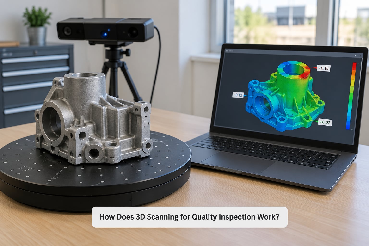
The workflow is the same whether the scanner sits on a tripod, an arm, a robot or a turntable. What changes is only the delivery mechanism and the accuracy class.
- Define the inspection requirement. Decide which characteristics matter, what tolerance applies and how many points of resolution you need. A cosmetic surface check and a bore-position check are different jobs and often different setups.
- Prepare and fixture the part. Clean it, remove burrs, and hold it in a fixture or on supports that do not touch the surfaces under inspection. Support points and fixturing marks show up in the scan, so plan for them.
- Calibrate and set the scan strategy. Run the calibration routine, then set resolution, exposure and the number of passes. More passes and tighter settings mean longer capture and better accuracy on fine detail.
- Acquire the point cloud. Cover the part from enough angles to reach surfaces that shadow each other, such as the inside of a deep bore or the underside of an overhang.
- Register the scan. The software aligns the cloud to the CAD model using features like planes, cylinders and edges. Best-fit alignment compares overall shape; datum alignment forces named features onto their theoretical positions so the numbers are meaningful.
- Analyse deviations. Apply tolerances, extract features, and read the colour map. Look at the pattern, not just the pass or fail.
- Report and archive. Save the scan, the aligned result, the pass or fail decision and the setup, so a year from now someone can reproduce the measurement.
The last two steps are where most shops under-invest. A scan without a saved registration and a tolerance scheme is a screenshot, and it will not survive an audit or a customer dispute.
Which 3D Scanning Methods Are Used for Quality Inspection?
Six families cover almost all production work. Accuracy below is a typical order-of-magnitude band for well-prepared parts at normal working distances, not a guarantee.
| Method | How it captures shape | Typical accuracy band | Best fit for |
|---|---|---|---|
| Structured light | Projected fringe patterns deformed by the surface | Around 0.02 to 0.05 mm | Detailed features, small to mid-size parts, matte surfaces |
| Blue light scanning | Blue structured light with high dynamic range | Around 0.015 to 0.04 mm | Machined and aerospace components where tolerance stacks are tight |
| Laser triangulation | A laser line or point, read by a camera | Around 0.03 to 0.08 mm | Hard surfaces, factory cells, high-speed automated inspection |
| Photogrammetry | Many photographs stitched by feature matching | Around 0.05 to 0.2 mm on good texture | Large parts, buildings, ship sections, textured surfaces |
| Arm-mounted | A sensor on a 6- or 7-axis arm, referenced by the arm | Around 0.05 to 0.1 mm | Heavy castings, forgings and weldments that will not fit a turntable |
| Industrial CT | X-ray projections reconstructed into a volume | Varies with part size and wall thickness | Internal defects, castings, additively manufactured parts |
LiDAR is a distance-sensing technology rather than an inspection standard, and it rarely handles the surface texture needed for CAD comparison. It turns up in large-scale photogrammetry and digital-twin work, not in the inspection cell.
How Accurate Does a Quality Inspection Scan Need to Be?
Required accuracy follows the tolerance, not the scanner’s headline number. If a feature is held to 0.1 mm, a scan accurate to 0.08 mm tells you almost nothing, because the measurement error and the tolerance are the same size. As a rule of thumb, aim for a measurement capability around one third to one tenth of the tightest tolerance you intend to judge, and treat the combined uncertainty of registration, calibration and environmental drift as part of that budget.
Several things eat into accuracy:
- Tolerance stack. Tighten the tolerance and the same scanner becomes the wrong tool.
- Feature size. Small radii and thin walls are harder to resolve; a scanner that reads a 5 mm radius well may blur a 0.5 mm fillet.
- Material and finish. Polished, dark and transparent surfaces all degrade the signal.
- Registration. The alignment of scan to CAD often contributes more error than the sensor itself. A sloppy datum alignment on a datum scheme the CAD does not match is the classic source of phantom offsets.
- Environment. Vibration near a press, temperature swings across a large part, and ambient light that leaks into an optical scan all show up in the result.
One thing worth saying plainly: repeatability and accuracy are not the same. A scanner can repeat the same measurement to within a few microns on the same setup and still sit half a millimetre off the true position because of a calibration or datum problem. Verify both before trusting the output.
How Do You Inspect a Part Against Its CAD Model?
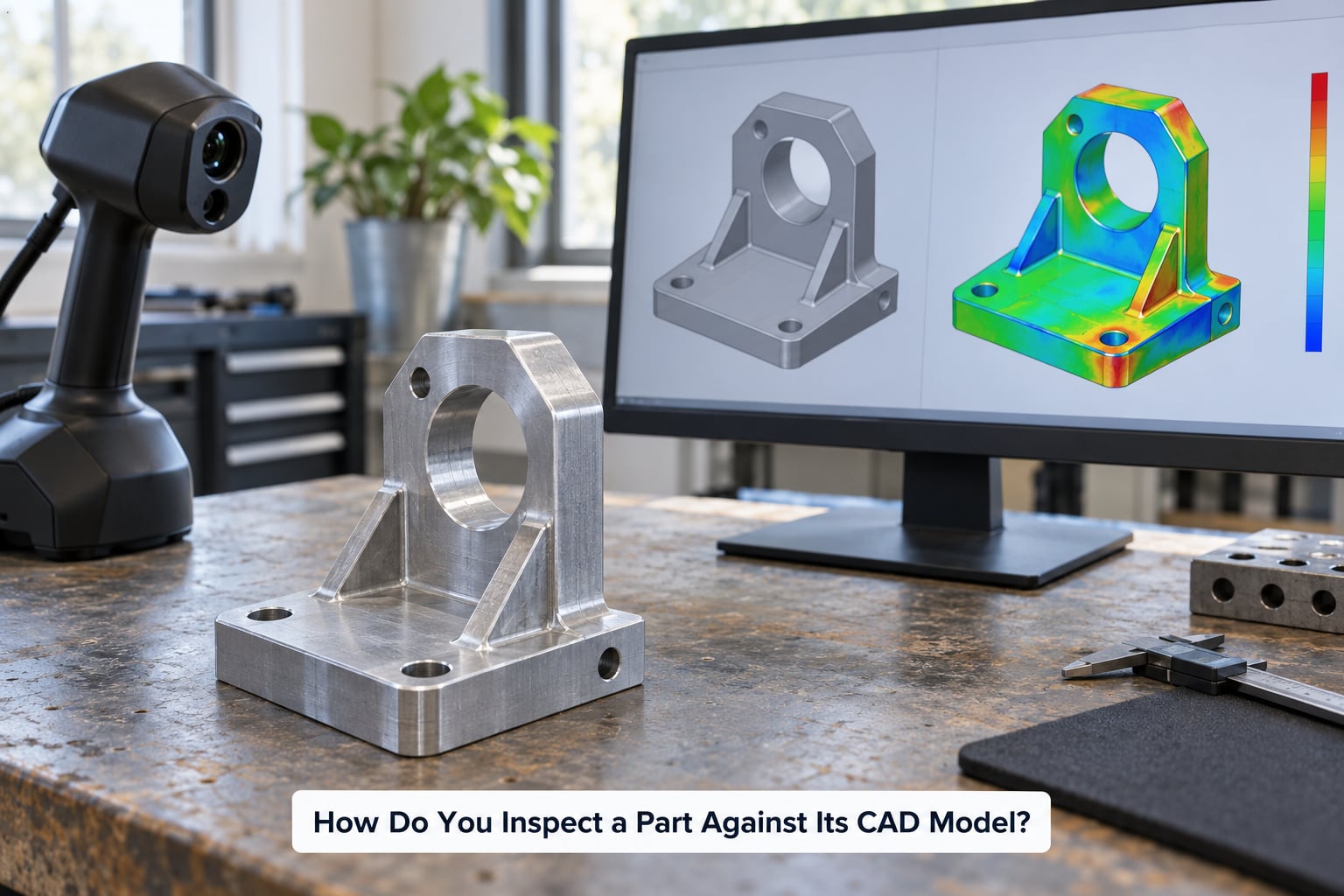
How 3D scanning for quality inspection compares a scan to CAD
Registration is the step that decides whether the report means anything. Best-fit alignment finds the position that minimises overall deviation, which is useful for a quick look and dangerous for judging a single feature: a part that is 0.1 mm off in every direction can align so that nothing reads out of tolerance. Datum alignment pins specific features to their theoretical locations first, so the remaining colour tells you about real error rather than about how the part happened to be placed.
From there, the analysis is routine:
- Deviation map. Read the pattern. A uniform offset suggests a setup or datum problem; a single hot spot suggests a local defect; a wave on a plate points at clamping or residual stress.
- Section views. Cut a virtual section through the model to measure a specific feature in profile, which is far more reliable than picking a point off a coloured surface.
- Feature measurement. Extract holes, cylinders, planes and surfaces and compare them with the drawing and any GD&T callouts.
- Pass or fail rules. Apply the tolerance scheme, including any geometric tolerance framework your customer requires, and let the software flag callouts outside limits.
- Reporting. Export a report that names the part, the revision, the setup and the software version. Store the raw scan alongside it.
What Are the Main Challenges in 3D Scan-Based Inspection?
Almost every scanning complaint traces back to light behaving badly on the surface. The fixes are mostly preparation and fixturing rather than better hardware.
| Situation | What goes wrong | Practical fix |
|---|---|---|
| Shiny or chrome surfaces | Specular reflection confuses the camera; data drops out or returns false points | Thin spray of flat matte developer, applied evenly and wiped back |
| Dark or black surfaces | Little light returns, so the signal is noisy | Same matte coating, or switch to a longer-wavelength method suited to dark parts |
| Transparent or translucent parts | Light passes straight through and the surface is not detected | Apply opaque coating, use ultrasonic or CT, or scan a coated replica |
| Deep cavities and blind bores | The sensor cannot see inside; the scanner runs out of depth | Use an extended-range probe tip, add a small rotary or tilt axis, or use CT |
| Occluded faces and undercuts | No line of sight means no data | Reposition the part or automate multiple scan positions |
| Thin features and edges | Features are resolved poorly or filleted away by the reconstruction filter | Raise resolution, take more passes, reduce smoothing, consider a smaller-field scanner |
| Hot parts and vibration | Scan drifts mid-capture and registers poorly | Let parts reach ambient temperature, scan at quiet times, use isolation mounts |
A matte coating solves two problems at once, which is why shops keep one on the bench. It converts a reflective surface into a diffuse one and it gives the reconstruction enough texture to work with. The cost is a slightly thicker surface, so stay well away from any feature you intend to measure.
When Is 3D Scanning Better Than Other Inspection Methods?
Each method answers a different question, so the honest answer is which failure you are trying to catch.
| Method | Strength | Weakness | Reach for it when |
|---|---|---|---|
| Calipers, gauges, micrometers | Inexpensive, instant, foolproof at the point of use | One dimension at a time, operator dependent | Simple incoming checks and production go/no-go |
| Visual inspection | Fast, cheap, catches appearance defects and handling damage | Subjective, lighting dependent, misses subtle offsets | Finish, colour and cosmetic faults |
| Contact profilometer | Direct, traceable surface texture and roughness | Slow, line-by-line, requires contact | Roughness, texture and small detail measurement |
| CMM | Highest confidence on discrete features and tight datums | Slow on freeform geometry, expensive, needs a controlled room | Tolerances around 0.01 mm or tighter, datums, bore position |
| 3D scanning | Full-surface coverage in minutes, portable, colour data | Less absolute traceability, sensitive to surface and environment | Freeform surfaces, large parts, high mix, first article checks |
| Industrial CT | Sees internal porosity, voids and inclusions | Costly, part size limited, slower throughput | Castings, welds and additively manufactured parts |
The best setups use both. Scan the whole part quickly to find where the error is, then send the CMM to the handful of features that need traceable numbers. That hybrid workflow cuts probe hours while keeping the defensible measurements.
How Can You Build a Reliable 3D Inspection Process?
A process that only works when one particular operator runs it is not a process. These are the parts that make it hold up.
- Match the device to the tolerance and the volume. Decide the tightest tolerance you will judge, the largest part, and the environment it lives in, then choose accordingly. Buying more accuracy than you need is easy; buying a scanner that cannot be fixtured for your part is expensive.
- Fix the reference standards. Calibrate against traceable artefacts appropriate to the scale being measured, and record what you used.
- Calibrate on a schedule you can defend. Follow the manufacturer’s interval, and add a check after any impact, move or large temperature change. Log the results so drift shows up as a trend instead of a surprise.
- Standardise fixturing. Build one fixture per part family, locate it on defined datums rather than eyeballing it, and keep the part at ambient temperature for a settling period.
- Write down scan settings. Resolution, passes, exposure and filter settings belong in a work instruction. Two operators should produce the same result from the same instructions.
- Train and verify. Run repeatability studies on real parts, including the ugly ones, and set a rule for when a measurement is out of confidence and needs a CMM.
- Run a measurement system analysis. Study gauge repeatability and reproducibility across operators and shifts before trusting the data on a controlled process.
- Store the evidence. Keep scans, alignments, reports, calibration records and software versions together, linked to the part serial number.
- Use external labs where independence matters. For supplier disputes and certification work, an accredited lab gives a result that stands up outside your building. If you need that route, look for ISO/IEC 17025 accreditation and ask what is in scope.
None of this is glamorous, and it is where most inspection programmes are won or lost. The scanner is the cheap part of the decision.
Frequently Asked Questions
How accurate are 3D scanners for quality inspection?
A well-calibrated scanner on a prepared part typically lands within 0.02 to 0.08 mm, depending on method and working distance. What matters more is the ratio to your tolerance. If the tightest tolerance you judge is 0.1 mm, a scan accurate to 0.08 mm is useless for that callout. Aim for measurement capability around one third of the tolerance, and verify accuracy against traceable standards rather than trusting a specification sheet.
Can 3D scanning replace a CMM?
For most freeform surfaces, large parts and high-mix production, yes, and it is much faster. For tolerances around 0.01 mm or tighter, for critical datum features, and where a traceable record is legally required, a CMM still sets the standard. The strongest setups use both: scanning to find where the error is, then the CMM to confirm the features that need defensible numbers.
How do you scan shiny or chrome parts?
Spray a thin, even layer of matte developer over the surface so the sensor reads diffuse reflection instead of a mirror image. Keep it away from any feature you plan to measure, since the coating adds a small thickness. For thin transparent parts, coating alone may still fail, and an ultrasonic method or industrial CT is the better answer.
Is calibration required for 3D scanners?
Yes, on a schedule set by the manufacturer and your own risk level. Calibrate against traceable artefacts at the scale you actually measure, log each result, and recheck after any impact, move or large temperature swing. Many shops also run a verification check against a known part at the start of each shift so drift shows up as a trend rather than a failed report.
What are the main types of 3D scanning technology?
The main families are structured light, blue light scanning, laser triangulation, photogrammetry, arm-mounted systems and industrial CT. Structured light and blue light dominate precision dimensional work on small and mid-size parts. Laser triangulation suits automated factory cells. Photogrammetry handles large textured objects. Arm systems cover heavy castings. CT is the only one that sees inside the part.
How long does a scan-to-CAD inspection take?
The capture itself is often a few minutes once the part is fixtured. Alignment and deviation analysis add another few minutes with a well-matched CAD model, so a full check usually fits inside a work instruction rather than a formal inspection plan. Add time for surface preparation on shiny parts and for stabilising temperature on large castings, and budget for post-processing when you are also building CAD.
Conclusion
Four things to do first, in order. Write down the requirement: which features, which tolerances, which environment. Pick the method to match that requirement rather than to match a specification sheet. Then validate on three or four real parts, including one you know is out of tolerance, and compare the result against a trusted reference. Once the numbers hold, write the workflow down and treat it like any other controlled process.
Scanning changes what inspection can cost and how long it takes, but only when the setup, the alignment and the reporting are disciplined. Get those three right and the coverage advantage pays for itself quickly.