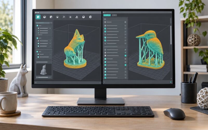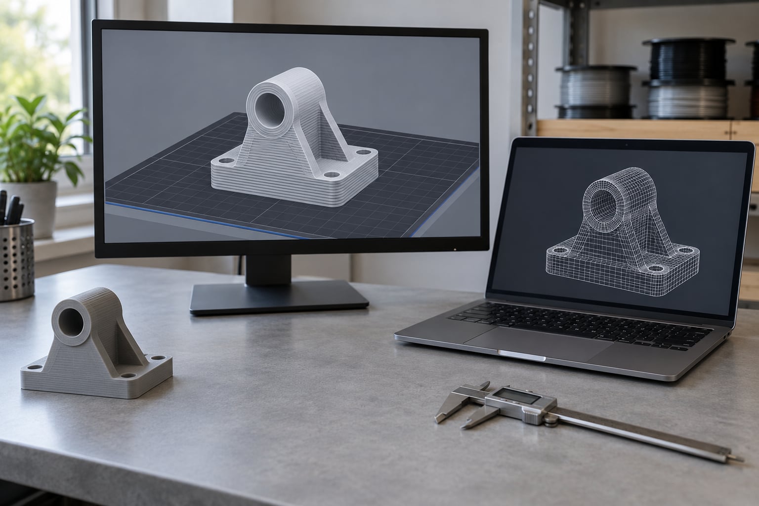
To preview an STL before printing, load it into the slicer you already use — Cura, PrusaSlicer, Bambu Studio, OrcaSlicer — and switch that program into preview mode. That view shows you the real dimensions, lets you scrub the print layer by layer, and highlights overhangs and support before a single gram of material is committed. A standalone viewer such as Windows 3D Viewer or MeshLab is the quick second look.
The reason to bother is that previewing catches the failures that eat an entire print: wrong scale, a model larger than your build plate, a non-watertight mesh, missing walls in the sliced output, or an orientation that leaves the part standing on fragile bridges. You can do all of it in about ten minutes.
One caveat early, because it matters more than most guides admit. A viewer renders triangles so you can look at them. It does not validate or repair them, and any tool that quietly “fixes” your geometry without telling you changes the file you are about to print. If the model is client CAD, unreleased, or under NDA, keep it local — a slicer, MeshLab or FreeCAD never uploads anything, while some browser viewers send your geometry to a server to render it.
Table of Contents
- What You Need
- Step-by-Step: How to Preview an STL Before Printing
- 1. Open the STL in a browser-based viewer
- 2. Check the mesh for holes, errors and broken surfaces
- 3. Check units and dimensions: how to preview an STL before printing at real scale
- 4. Inspect shape, wall thickness and fine details
- 5. Preview the print orientation and supports
- 6. Check the sliced layers in your printer software
- Common Mistakes
- Frequently Asked Questions
- Can I preview an STL file online without uploading it?
- Does repairing an STL make it safe to print?
- Why does my STL look tiny or huge in the slicer?
- Can I see supports and overhangs in an STL viewer?
- Does a clean slice guarantee that the model will print successfully?
- Bottom Line: What to Do First
What You Need
You need less than you would expect. All six items below are free or already on your machine, and the whole preview takes minutes rather than an evening.
- The STL file itself. Have the original, not a copy someone re-exported. The same part exported from CAD in inches instead of millimeters is the single most common problem on this whole page.
- The slicer for your printer. Cura for most Ultimaker and RepRap machines, PrusaSlicer for Prusa, Bambu Studio or OrcaSlicer for Bambu and Creality kits, Simplify3D or Flashforge Artisan for those ecosystems. Using the slicer you will actually print from means the preview matches the print.
- A standalone viewer. Windows 3D Viewer ships with Windows 10 and 11. MeshLab, FreeCAD and Blender are free, offline and handle mesh inspection far better than any file browser.
- Your printer’s specs. Build volume in millimeters for each axis, nozzle diameter, and whether you are printing filament or resin. Without these you cannot judge fit, wall thickness or overhang limits.
- A known reference object. A bank card measures 85.6 by 53.98 mm. A drinks can is roughly 66 mm in diameter. Drop one beside the model on screen and your scale problem disappears.
- Optional: a mesh checker. FreeCAD’s Mesh workbench, MeshLab, or your slicer’s built-in checks. Needed once you suspect holes or non-manifold geometry.
If you work on tablet-sized files, note that a large scan can stall even good viewers. Models under roughly 100,000 triangles open instantly; a few million will crawl or hang, and a scan exported straight from photogrammetry software is the usual culprit.
Step-by-Step: How to Preview an STL Before Printing
Six stages, in this order, and you stop at the first one that fails. Previewing is not a single click — it is a short chain where each stage answers a question the previous one raised.
1. Open the STL in a browser-based viewer
The quickest first look needs no installation: open a browser, load the file, and look at it. Pick a viewer that states it processes files locally in your browser, then check that claim yourself — in the browser’s developer tools, open the Network tab, drop the file, and confirm no upload request fires when it renders. If the model is client work, skip this stage entirely and go straight to your slicer or MeshLab, both of which run fully offline.
Drag to rotate, scroll to zoom, right-drag to pan. Spend the first minute turning the model all the way around at full zoom, because the problems that ruin prints hide on the back. Toggle between shaded and wireframe rendering: shaded shows form and silhouette, wireframe shows the raw triangle topology underneath.
How you know it worked: the silhouette looks like the object you expected, from every angle, at a plausible size relative to the reference you are comparing it to.
2. Check the mesh for holes, errors and broken surfaces
A viewer shows you geometry; a mesh checker tells you whether that geometry is sound. Switch to wireframe and look for the classic signs: holes that let you see through a solid wall, stray triangles floating in space, faces that intersect themselves, and internal shells sitting inside a part you believed was solid.
In FreeCAD, open the file, switch to the Mesh workbench, and run the geometry checks — non-manifold edges, self-intersections, holes, duplicate points — then read the report. MeshLab’s Filters and Undo menus carry equivalents. Cura also does this without leaving the program: right-click the model in the build plate and run the overhang check and the wall thickness check.
If a tool offers to repair the mesh, treat that as a separate decision, not a pop-up to dismiss. Repair closes holes and merges nearby vertices, and it can flatten a thin feature you needed. Repair, then look at the model again from the same angles you used before.
How you know it worked: a mesh checker reports no non-manifold edges and no open boundaries, or you know exactly which feature the repair flattened.
3. Check units and dimensions: how to preview an STL before printing at real scale
An STL stores bare coordinates with no unit attached, which is why models arrive 25.4 times too big or too small. If CAD was drawn in inches and the exporter wrote those numbers expecting millimeters, the part is 25.4 times larger than intended on screen. If it went the other way, the model looks like a toy next to your printer.
Open the measurements or bounding box readout in your viewer and compare X, Y and Z against the real object. That is the whole check: 100 mm in the file should be 100 mm on your desk. Also compare against the build volume at this stage, not later — many hobby FDM machines give you roughly 200 to 250 mm on each axis, and a 260 mm model is a no-go no matter how good it looks.
Fix scale in the slicer rather than in the mesh where you can. PrusaSlicer has a Scale field in the object properties panel and a Scale tool in the toolbar; Cura’s scaling lives in its tool bar with uniform and non-uniform options. Apply one uniform factor to all three axes and re-measure.
How you know it worked: the bounding box matches the real object within about a millimeter, and every axis fits your printer’s build volume with room for the skirt.
4. Inspect shape, wall thickness and fine details
Now zoom in on the parts that decide whether the print succeeds. With a 0.4 mm nozzle, a wall thinner than about 1 mm prints as a single wobbly line, so any feature you care about should be at least two nozzle widths wide. Resin printers tolerate thinner walls, but the same thin-feature rounding applies where the detail is smaller than the nozzle.
Look specifically at fragile projections such as fingers on a miniature or the arm of a bracket, recessed detail that sits below the nozzle’s reach, sharp edges that will be rounded off no matter what, and any cavity opening narrower than your nozzle. A hole you cannot fit the nozzle through is a hole you cannot clear, and it will trap resin or support material.
Use the section or clipping view to cut through the part and confirm it is solid where you expect it to be. This is also the fastest way to catch a model that is hollow inside when the designer sold it as a solid part.
How you know it worked: no visible feature is thinner than two nozzle widths, and every recessed detail is reachable by the tool head.
5. Preview the print orientation and supports
Drag the model onto the virtual build plate and rotate it until the part sits the way it will actually sit. Orient for printing, not for looks: the flattest, widest surface against the plate gives you the best first layer and the least support.
Most FDM printers can hold an overhang at roughly 45 degrees without support, so anything steeper that points downward needs it — unless you can rotate the part so that face points up instead. Any horizontal span with nothing under it is a bridge, and bridges print best when kept short and printed in a material that does not sag much.
Watch the build plate for the other orientation problems. A tiny island of geometry with no attachment wastes time and often fails. Skirt and brim settings need room too — if the brim would hang off the edge of the plate, the first layer will not land.
How you know it worked: the largest possible area touches the plate, no overhang steeper than about 45 degrees faces open air, and every floating piece is intentional.
6. Check the sliced layers in your printer software
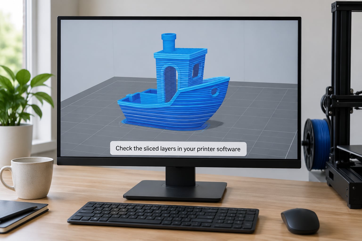
The last stage is the slicer itself, and each one puts the preview toggle in a different place. In PrusaSlicer, the two small icons at the bottom left of the viewport switch between plater and preview — and PrusaSlicer does not switch back automatically when you load a new file, which is why so many people load a model, see an empty view and assume the import failed. In Cura, use the preview toggle in the toolbar, then pick X-Ray or wireframe from the view mode control. In Bambu Studio and OrcaSlicer, the Preview button in the top toolbar hides the build plate, and the vertical slider on the right scrubs through the layers.
Scroll through the layers slowly and watch what the slicer actually produced. Confirm the top and bottom layer counts match your settings, that walls and perimeters wrap the part as expected, that infill appears inside rather than through it, and that supports and bridges look the way you intended. The slicer’s material and time estimate at the bottom is also your first cost estimate.
If a part looks sliced but solid where it should be open, or open where it should be solid, stop there. That is a geometry or scale problem, not a settings problem, and re-exporting beats re-slicing.
How you know it worked: every layer looks the way the sliced object should, the estimate is plausible, and the mesh checks came back clean.
Common Mistakes
Most failed previews come down to seven habits. Each has a straightforward fix.
- Judging scale only from the model view. A part can look perfectly proportioned and still be 25.4 times too large. Always read the bounding box and compare it to something of known size.
- Trusting a viewer that repaired the mesh without telling you. Silent repairs quietly change thin walls and small features. Look for the original triangle count before and after, and re-run the mesh checks.
- Overlooking internal surfaces. X-ray view and section clipping exist for a reason. A hollow shell with a trapped void prints badly even though the outside looks perfect.
- Choosing orientation for appearance. The prettiest angle is rarely the flattest one. Rotate for first-layer contact and overhang angles, and let the supports do the rest.
- Forgetting printer-specific clearances. Model fit is not enough. The nozzle needs room over the build plate, and a brim or skirt can push a part right off the edge.
- Assuming a successful slice guarantees a successful print. A clean slice means the mesh was readable, not that the part is manifold, dimensionally right or printable at your nozzle size.
- Previewing with the wrong material profile. Layer height, nozzle and resin type change what is achievable. A feature that survives a 0.2 mm layer profile may vanish at 0.4 mm.
Before you hit print, run through four quick checks. Read the bounding box one more time and confirm it fits your build volume. Look at the first layer and confirm every island touches the plate. Skim the slice at 50 percent and check for thin walls that lost their perimeters. And make sure the mesh check reported no non-manifold edges — if it did not, run it.
Frequently Asked Questions
Can I preview an STL file online without uploading it?
Yes, but only with a viewer that processes files locally in your browser. Many online STL viewers upload your geometry to a server to render it, which is fine for a downloaded model and a bad idea for client CAD, unreleased work or anything under NDA. Pick a tool that states local processing, then confirm it yourself by opening the browser developer tools, selecting the Network tab, dropping the file and checking that no upload request fires. Your slicer, MeshLab and FreeCAD are the safest choices because they never touch the network.
Does repairing an STL make it safe to print?
It fixes specific problems, not all of them. Mesh repair closes holes, merges duplicate vertices and resolves self-intersections, which is exactly what most slicers need. But repair does not fix wrong scale, a model that exceeds your build plate, walls thinner than your nozzle, or an orientation with severe overhangs. Repair can also flatten thin features you wanted to keep, so always look at the model again afterwards and re-run the mesh checks before you trust it.
Why does my STL look tiny or huge in the slicer?
Because STL files store bare coordinates with no unit attached, so the exporter decides what a number means. CAD drawn in inches and exported as if the numbers were millimeters produces a model 25.4 times too big, and the reverse produces one 25.4 times too small. Open the bounding box or measurements panel and compare it to a reference object you know the size of. If it is off by that factor, set a uniform scale of 1/25.4 or 25.4 in your slicer and re-measure.
Can I see supports and overhangs in an STL viewer?
Not in a plain standalone viewer, because supports are a slicer decision rather than part of the mesh. Overhang detection belongs in the slicer, where Cura offers a right-click overhang check on the model in the build plate, and PrusaSlicer, Bambu Studio and OrcaSlicer highlight overhangs once you slice. What a viewer can tell you is the shape, so judge which surfaces angle downward and over roughly 45 degrees, then take the model into your slicer to see the real support structure.
Does a clean slice guarantee that the model will print successfully?
No. A clean slice means the slicer could read the geometry and generate toolpaths, nothing more. The mesh can still be non-watertight, hollow when you expected solid, or scaled wrong, and features thinner than your nozzle will vanish or come out as a single wandering line. Treat a clean slice as one checkpoint: check the bounding box, run a mesh check for non-manifold edges, and look at the first layer and the walls before committing material and hours.
Bottom Line: What to Do First
Open the file in your slicer and read the bounding box against a credit card before you do anything else. If the numbers check out, rotate the part flat, slice, and skim the layers once; if they do not, fix the scale in the slicer and start the six stages again. Ten minutes of that is cheaper than any failed print.