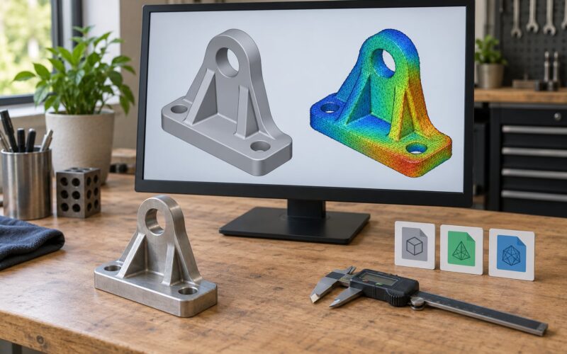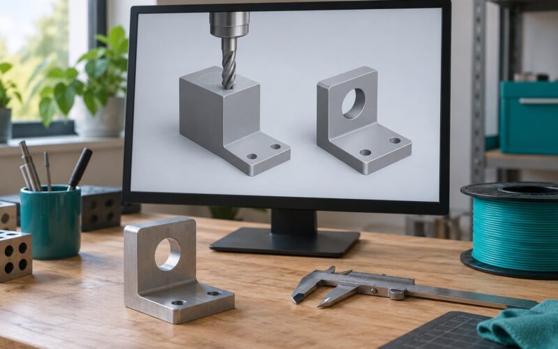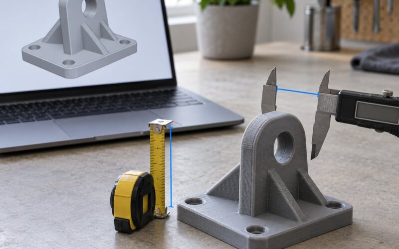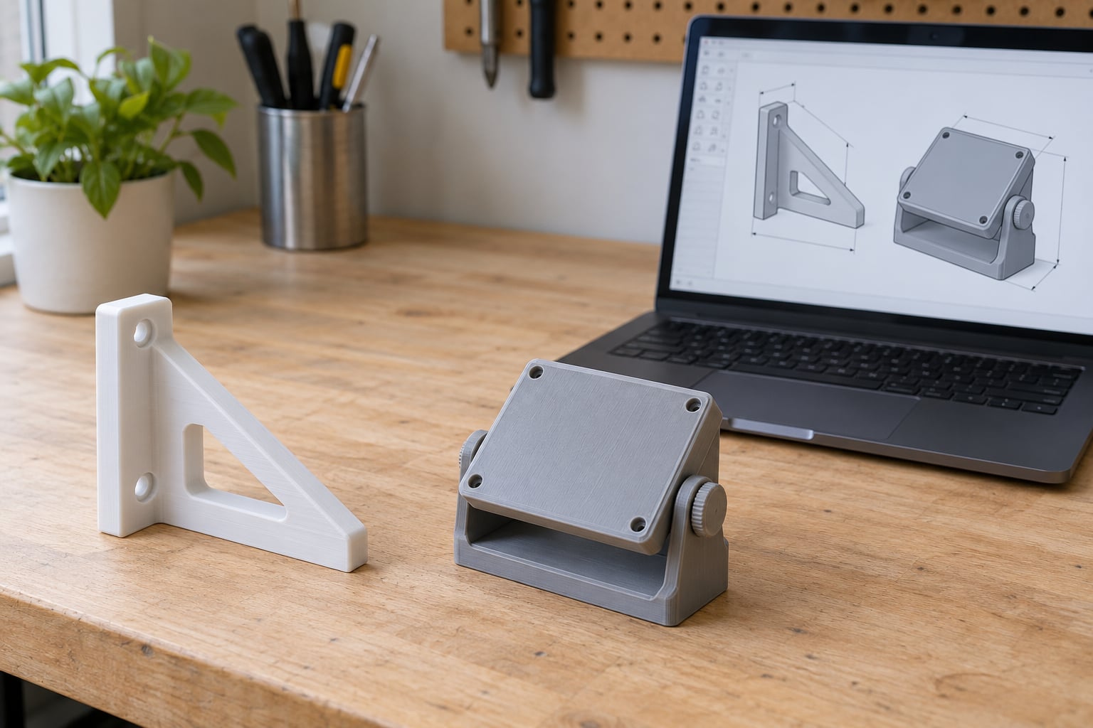
Parametric design for 3D printing is a way of building models where the geometry is driven by named variables instead of fixed numbers. Change the wall thickness once and every dependent feature updates with it, which means one file can produce an entire family of correctly sized parts. It is the difference between editing a model and reshaping it from scratch.
I use it whenever I need the same thing at a different measurement: a planter insert that has to fit a pot I already own, a bracket for a slightly odd shelf, an adapter between two hose fittings. For one-off decorative shapes it is overkill, and I skip it.
Table of Contents
- What Is Parametric Design for 3D Printing?
- How Does Parametric Design Work in 3D Printing?
- What Makes a Parametric Model Useful for 3D Printing?
- Which Parameters Should You Control?
- What Software Can You Use for Parametric 3D Printing?
- FreeCAD or OpenSCAD for Parametric Design for 3D Printing
- How Do You Create a Parametric Model Step by Step?
- Which File Format Should You Share?
- How Do You Make Parametric Models Print Successfully?
- Where Does Parametric Design Beat Conventional 3D Modeling?
- Frequently Asked Questions
- What is parametric design and how does it work?
- What is the difference between parametric and non-parametric design?
- Is parametric design still relevant?
- What does parametric mean in 3D printing in plain language?
- Are STL files parametric?
- Is anything illegal to 3D print?
- Conclusion
What Is Parametric Design for 3D Printing?
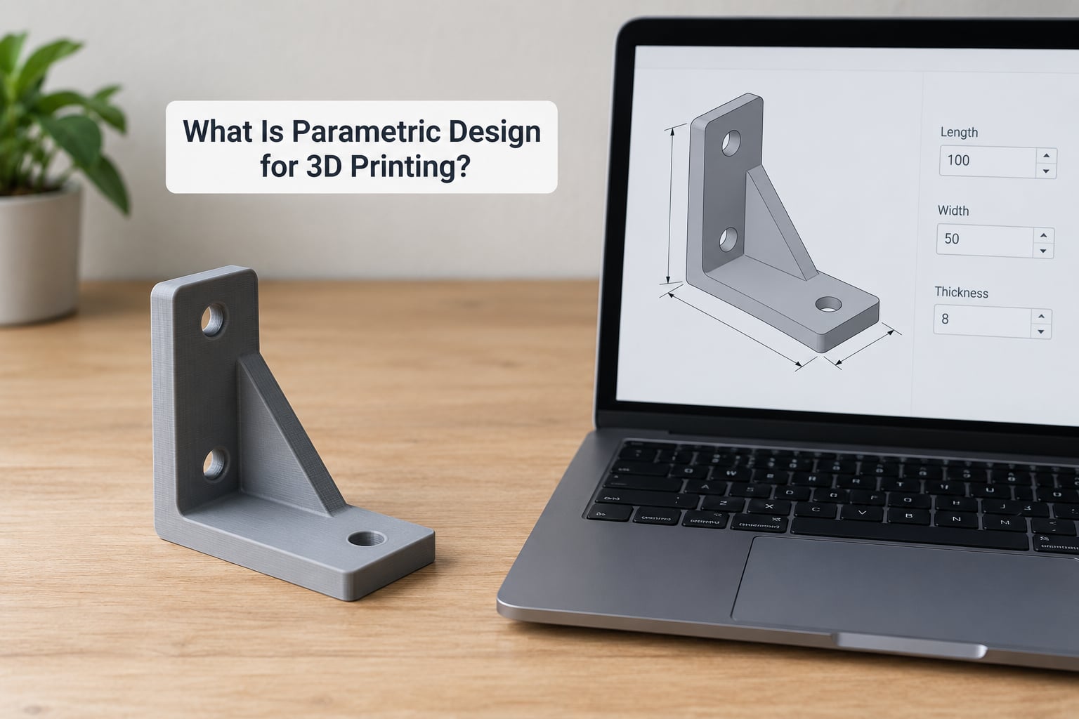
Parametric design is a modeling approach in which a 3D model’s geometry is controlled by named variables and constraints rather than fixed dimensions. You type a value once into a parameter list, sketch features reference that name instead of a typed number, and the model regenerates every time a value changes. Nothing needs to be redrawn by hand.
Five ideas do all the work:
- Parameter — a named value such as
wall_thicknessorhole_diathat you can edit in one place. - Constraint — a rule that holds geometry in relationship, like a sketch dimension locked to a parameter, a hole concentric with an arc, or two faces kept parallel.
- Feature history — the ordered list of operations that built the solid: sketch, extrude, fillet, chamfer, pocket. The model is the recorded result of that sequence, not a frozen shape.
- Associativity — the link between early geometry and late features. Change the sketch and the downstream fillet follows it.
- Regeneration — the CAD kernel re-running the whole feature tree with the new values and reporting any feature it cannot satisfy.
Community definitions tend to land in the same place: on the r/3Dprinting thread that ranks above most written guides, parametric modelling is described as everything being defined by dimensions, constraints and relationships. That is the whole idea in one sentence.
How Does Parametric Design Work in 3D Printing?
Take a wall hook. The naive way is to draw a shape, type 40 mm into an extrusion, and export an STL. If your wall stud spacing is 35 mm instead, you go back, find the four or five places that number touches, and edit each one. Miss one and the part is scrap.
The parametric version looks like this:
- Create a parameter list and name the values:
hook_length,hook_width,plate_thickness,screw_dia,fillet_r. - Sketch the plate and drive its width from
hook_width. - Pattern the mounting holes along that width so their spacing follows automatically.
- Apply the curved arm, then a fillet whose radius is
fillet_r.
Set hook_width to 35 and the plate shortens, the holes re-space, and the screw diameter stays 4 mm. The screw holes do not scale with the plate, which is the entire reason scaling an STL in your slicer is not a substitute — scaling makes a 5 mm screw hole become 4.4 mm and the thread stops biting.
Under the hood, this works through a feature tree and a constraint solver. Every time a parameter changes, the solver re-evaluates the sketch constraints, then replays each timeline feature in order. If a value makes a step impossible — a fillet larger than the wall it sits in, a chamfer on an edge that no longer exists — regeneration stops and flags that step instead of silently producing nonsense.
What Makes a Parametric Model Useful for 3D Printing?
Five payoffs show up almost immediately at the printer:
- Correct fit at any size. Wall thickness, hole diameter and clearance stay constant while the outline changes, so a variant actually fits the thing you are attaching it to.
- Personalization without rebuilding. Engraving text, a name, a wrist measurement or a pot diameter is a field change, not a redraw.
- Repeatable versions. Everyone in a household or workshop prints the same organizer at a different width from one shared file.
- Faster revisions. A failed print teaches you one thing; you change the parameter that caused it and re-export.
- Printability baked in. Minimum wall, minimum hole and overhang limits can live in the same parameter list, so a variant cannot be generated that the printer physically cannot produce.
Which Parameters Should You Control?
Start small. Six or seven values cover most printed parts, and each one should earn its place:
- Overall dimensions — length, width, height, and any overall envelope limit.
- Wall thickness — usually three or four times your nozzle diameter on FFF printers. Set it once and let shells, ribs and tabs follow.
- Hole diameter — mounting holes and clearance holes, with separate clearance values where a bolt needs to pass through.
- Fillet and chamfer radius — these set stress risers and affect how the part prints; parametric fillets are easy to over-radius.
- Tolerance or clearance offset — a small negative offset on mating features that compensates for printer accuracy and material shrinkage.
- Print-process values — overhang angle limit, infill density for internal ribs, and orientation.
Anything you would otherwise type twice belongs in the list. Anything you type once and never change does not.
What Software Can You Use for Parametric 3D Printing?
All the tools below do genuine parametric modeling. They differ mainly in how you express intent: with a mouse in a sketch, with typed code, or with a visual node graph.
| Tool | Style | Learning curve | Native parametric file | Best for |
|---|---|---|---|---|
| Fusion 360 | Constraint-based CAD with a user parameters dialog | Moderate | .f3d | Makers moving up from Tinkercad who want named variables |
| FreeCAD | Constraint-based CAD, open source | Steep | .FCStd | Desktop parametric work with no subscription |
| OpenSCAD | Code-driven, variables and modules | Low if you have never coded, high if you have | .scad | Generative families, spirals, lattices, text and maths-driven shapes |
| SolveSpace | Lightweight constraint-based, single file | Low to moderate | .slvs | Small parts and quick sketches on modest hardware |
| Onshape | Browser-based CAD with parameters | Moderate | .onshape / native documents | Shared editing and working from any machine |
| Tinkercad | Shape-combining, not truly parametric | Very low | .t3d | Simple parts and a first taste of dimensioning |
Tinkercad is the outlier here. You can place a box and set its size in the properties panel, but there is no parameter list and no feature tree, so changing one value does not propagate. It is a fine starting point for shapes, and a dead end for parametric design for 3D printing.
FreeCAD or OpenSCAD for Parametric Design for 3D Printing
If you want to learn parametric modeling with real named variables, Fusion 360 is the gentlest on-ramp that matches how repositories expect files to arrive, and Tinkercad graduates usually land there first. Onshape is the same idea without an install.
If you would rather write the dimensions down and let the model build itself, OpenSCAD is shorter to learn and far harder to outgrow. A pot insert becomes a dozen lines of variables and a difference operation, and changing the pot diameter touches one number. FreeCAD and SolveSpace make more sense if you want the constraint solver to hold relationships for you while you sketch.
How Do You Create a Parametric Model Step by Step?
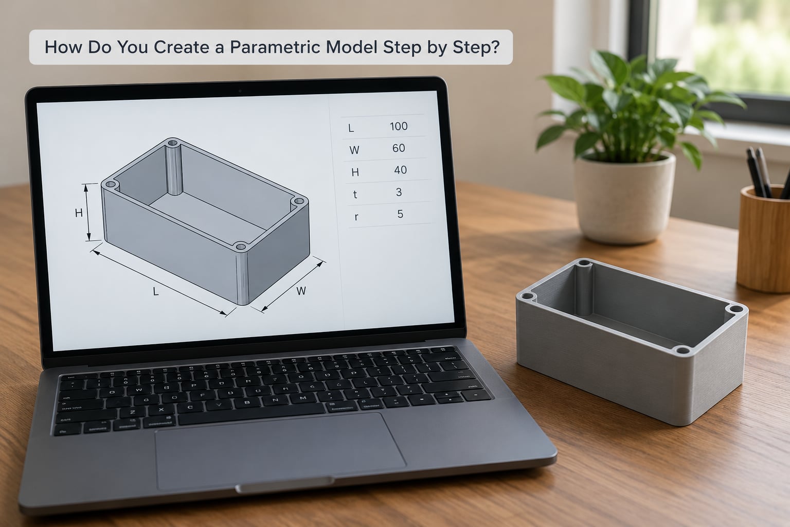
- Write down the design intent. In one sentence: this is a bin that holds 400 ml and stacks on the one below it. Intent tells you which dimensions are relationships and which are free.
- List the parameters before you model. Outer width, outer depth, height, wall thickness, corner radius, clearance. Resist adding more at this stage.
- Build the base solid from parameters only. Sketch one rectangle driven by width and depth, extrude it by height. Never type a raw number into an extrusion field.
- Add features with references. Shell the part using
wall_thickness, fillet the corners withcorner_r, place holes using expressions tied to named diameters. - Add tolerance offsets where parts mate. A lid that needs to sit on the bin gets a small negative clearance parameter rather than a hand-tweaked number.
- Test the extremes. Set every parameter to its minimum, regenerate, and check the feature tree still solves. Then set them all to maximum. This is where broken models show themselves early.
- Check printability against the process. Confirm the smallest wall, the smallest hole and the worst overhang for your nozzle and material at both extremes.
- Export the right files. A mesh for printing and the native parametric file for anyone who wants a different size.
Which File Format Should You Share?
This trips people up constantly. An STL or 3MF is a frozen mesh: it holds the shape you exported and nothing else. No parameters, no history, no way to change a value without remodelling.
| Format | Editable parameters? | What it is good for |
|---|---|---|
| .f3d | Yes, plus the full design history | Sharing a Fusion 360 model with its variable list intact |
| .FCStd | Yes, plus history | Sharing FreeCAD work |
| .scad | Yes, it is source code | Sharing OpenSCAD models, which stay editable in any text editor |
| .STEP | No parameters, but solid geometry rather than a mesh | Sending precise geometry to another CAD user or a machinist |
| STL / 3MF | No | Slicing and printing; 3MF also carries slicer settings |
When a repository listing claims to be parametric, check the file list before you plan anything around it. Plenty of uploads ship a flattened mesh with the word parametric in the title, and you will end up rebuilding the part from measurements.
How Do You Make Parametric Models Print Successfully?
A parametric model can generate variants the printer cannot handle. These checks keep that from wasting filament.
Minimum features. On FFF printers the practical floor is roughly two to three extrusion widths for a wall and about twice your nozzle diameter for a small hole. Make those limits parameter expressions so an impossible variant fails on screen rather than halfway through a print.
Overhangs. Anything past about 45 degrees from vertical wants support. A hook arm that gets longer with a parameter may cross that line, and the fix is to change orientation or add a small rib rather than accept a support scar.
Tolerances and shrinkage. FFF parts usually need a clearance offset of a few tenths of a millimetre for a moving fit, and more for a snap. Keep the offset as its own parameter so you can dial it after the first test instead of rebuilding the geometry.
Material behaviour. Resin shrinks as it cures, which matters more than the numbers suggest if you are fitting several printed parts together. Print one test coupon at your chosen values before generating the whole family.
Orientation and infill. Layer direction sets strength. Drive orientation from a parameter when it is a choice worth revisiting, and treat infill as a print setting rather than model geometry — unless the infill is structural, as it is in a lattice or a lightly ribbed panel.
Test one variant before the batch. Print the smallest and the largest size in your range first. If both come out sound, the sizes between them are usually uneventful.
Where Does Parametric Design Beat Conventional 3D Modeling?
Parametric modeling wins whenever you will need the same part more than once, at a measurement you do not know yet. That covers organizers and bin systems in several widths, adapters between mismatched parts, brackets for irregular measurements, jigs and fixtures, prosthetic sockets sized to a person, modular furniture joints, and product lines that ship in a range of sizes from one master file.
It also wins on revision speed. When a printed part fails in your hands, a parameter change and a re-export takes minutes, where direct manual modeling means re-dimensioning every sketch by hand.
Conventional modeling is still the right call for art pieces, organic sculpted forms, one-off repairs to a broken household object, and anything derived from a 3D scan. If the shape came from a scan and you will print it exactly once, there is nothing to parameterize.
Is it still relevant? More so than most buzzwords in this field. Scripted CAD and node-based tools such as Grasshopper let you drive geometry from data, and AI-assisted parameter search is being used to sweep a design space for shapes that meet weight or stiffness targets. The underlying idea has not moved: named values in, solid geometry out.
Frequently Asked Questions
What is parametric design and how does it work?
Parametric design is a modeling approach where a 3D model’s geometry is controlled by named variables and constraints instead of fixed dimensions. You enter values such as width, height, wall thickness and hole diameter into a parameter list, and sketches and features reference those names. When a value changes, the CAD kernel re-runs the whole feature tree and rebuilds every dependent feature.
What is the difference between parametric and non-parametric design?
A non-parametric model is a fixed shape, usually exported as an STL or 3MF. Changing its size means scaling it, which changes wall thickness, hole sizes and clearances at the same time. A parametric model keeps those features at their intended values while the outline changes, because each dimension is driven by a parameter you edit deliberately.
Is parametric design still relevant?
Yes. Scripted tools like OpenSCAD and node-based editors like Grasshopper extend the same idea into data-driven and generative work, and AI-assisted tools increasingly help search a range of parameter values for a result that meets specific targets. For anyone printing families of parts, adjustable brackets or custom-fit adapters, parametric modeling still saves more time than it costs.
What does parametric mean in 3D printing in plain language?
It means the model is described by a list of editable values rather than baked-in measurements. A listing is usually called parametric when it ships the source CAD or code file, so you can enter your own numbers and get a correctly sized part. If it only offers an STL, the shape is fixed and you cannot change anything but the print scale.
Are STL files parametric?
No. An STL is a triangle mesh, a snapshot of a shape with no parameter list, no feature tree and no history. A 3MF file is similar, though it can carry slicer settings. To get a genuinely adjustable model you need the native file such as .f3d, .FCStd or .scad, or the script that generates it, which is why repositories ask you to pick a size before exporting.
Is anything illegal to 3D print?
Legality is about the object and your jurisdiction, not about whether the model is parametric. Rules on firearms, detachable components and intellectual property apply equally to any file. If a design looks borderline, check your local regulations before printing, and be careful with trademarks or copyrighted logos regardless of the file format.
Conclusion
Start small. Pick the one dimension you keep having to change, give it a name, and drive the sketch from that name instead of a typed number. Set every other value to fixed numbers for now and print one small test at a deliberately awkward size. If it fits and the feature tree survives, you already have a parametric model, and adding the next parameter is a five-minute job.