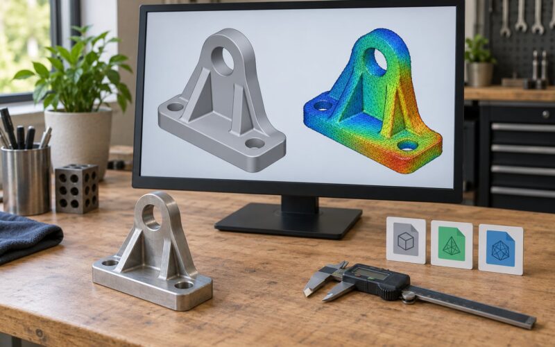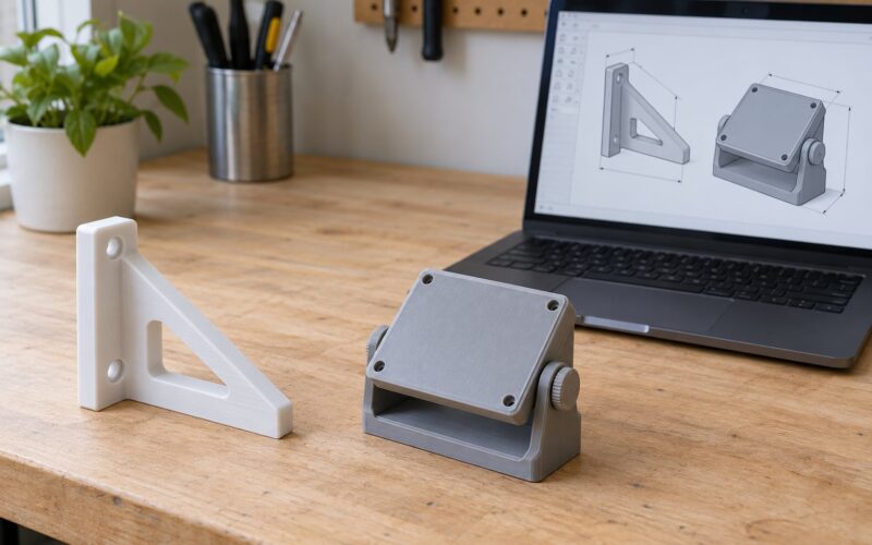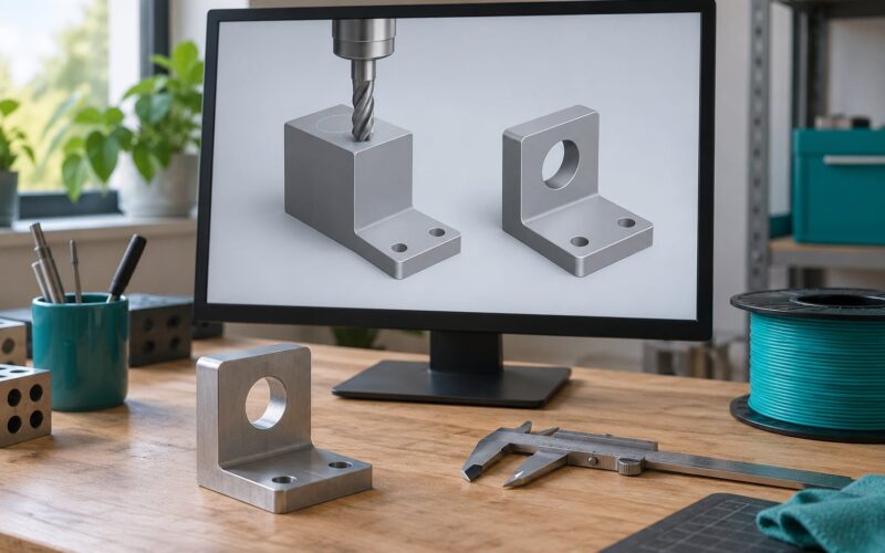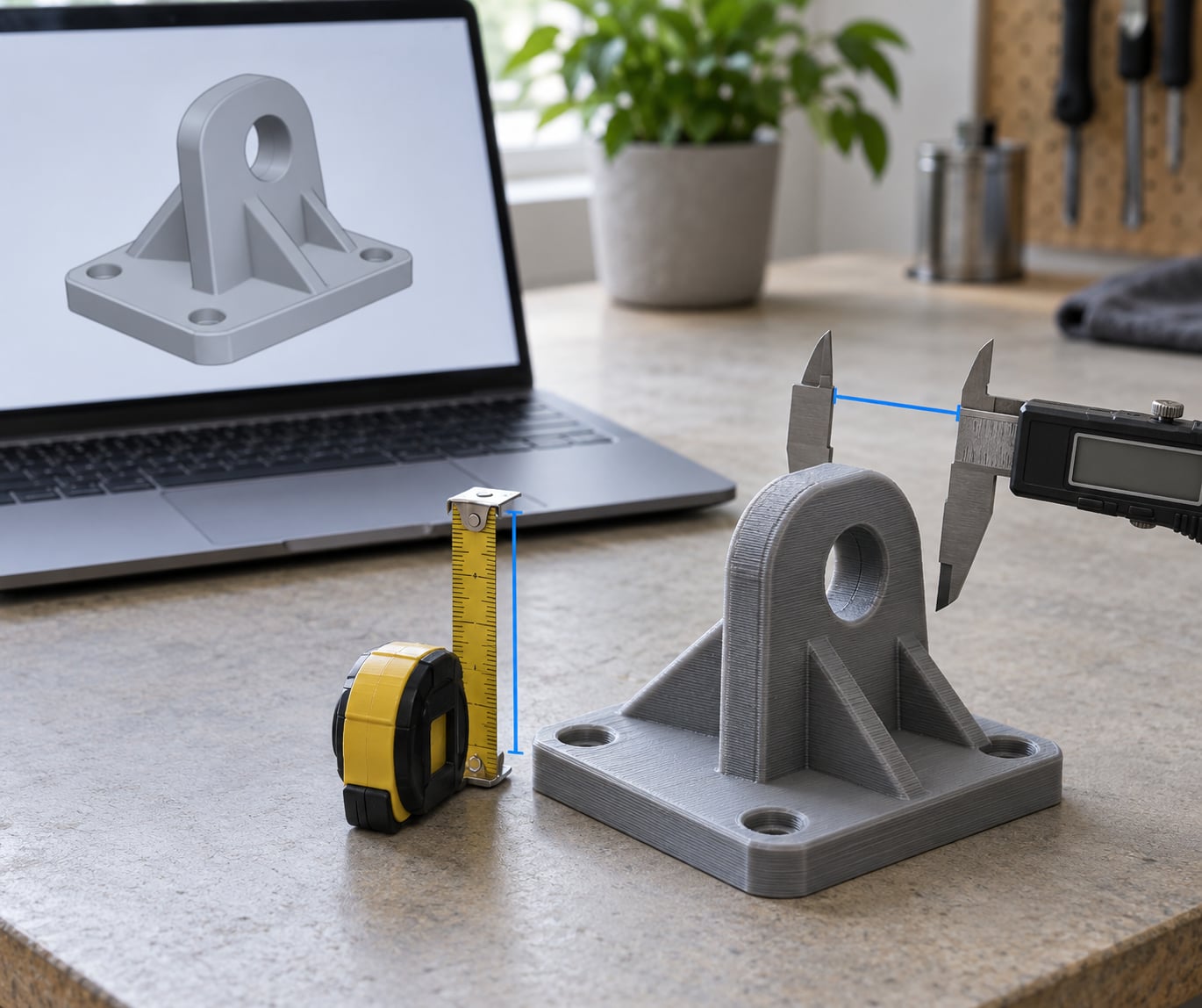
To scale a model for 3D printing accurately, measure the part in your CAD program or slicer, divide your target real-world dimension by the current dimension, then apply that single scale factor uniformly on all three axes. Export, measure, and only then adjust for your printer’s own error.
That last part is where most guides stop early. Resizing a file is easy. Getting a printed part that lands within a tenth of a millimeter of the size you asked for takes one more loop: calibrate steps per mm, correct flow and first-layer oversize, then verify with calipers on a test cube. This guide covers both halves, in the order you should actually do them.
One quick framing before the steps. STL files carry no real-world unit, so the same file can arrive at 28 mm or 200 mm depending on the designer who exported it. Size is the measurement. Scale is the ratio to a real object. Getting the size right makes a model match other models and fit your build volume; getting the print dimensionally accurate is a separate, second job.
Table of Contents
- What You Need
- Step-by-Step: How to Scale a Model for 3D Printing Accurately
- Step 1: Back Up the Original Model and Confirm Its Units
- Step 2: Choose the Part or Geometry to Scale
- Step 3: Enter a Reliable Target Dimension
- Step 4: Apply Uniform Scaling and Check the Scale Factor
- Step 5: Inspect Features That Scaling Can Distort
- Step 6: Measure, Validate, and Export the Scaled Model
- Common Mistakes
- Scaling the whole assembly instead of one part
- Typing the scale percentage from a visual estimate
- Applying scale twice
- Leaving non-uniform scale in Blender
- Ignoring thin features when scaling down
- Not rechecking dimensions after export
- Fixing a printer problem with the scale slider
- Forgetting the datum
- Frequently Asked Questions
- Can you scale up a 3D model?
- What are the differences between uniform and non-uniform scaling?
- Should I scale in the slicer or in CAD?
- How do I fix non-uniform scale in Blender?
- How do I make 3D prints more dimensionally accurate?
- Why is my 3D print the wrong size when the model looks correct?
- Conclusion
What You Need
You need four things, and the first two take ten minutes and prevent most of the failures I see.
- The model file, plus a separate copy. Save a new version before you touch anything, because a baked-in scale factor is very hard to find again once it is inside the mesh.
- A program that scales precisely: your slicer, Blender, Meshmixer, Fusion 360, or a browser tool. Drag-scaling in a viewer is not scaling.
- The real target dimensions in millimeters, from calipers, a manufacturer drawing, or a known standard.
- Printer and material context: build volume, nozzle size, layer height, and whether the printer is FDM or resin.
- Digital calipers for the verification pass. A ruler will not settle a 0.2 mm question.
Checking units before scaling is what stops the classic failure. A model measured in centimeters and treated as millimeters prints at one tenth of the intended size, and a model in inches treated as millimeters prints roughly 25 times too large. Both fit on screen and both are wrong. Open the measurement tool in your CAD or slicer first and record the raw bounding box numbers before deciding on a scale.
Slicer menu paths move between releases, so compare the steps below against the 2026 build you are actually running.
Step-by-Step: How to Scale a Model for 3D Printing Accurately
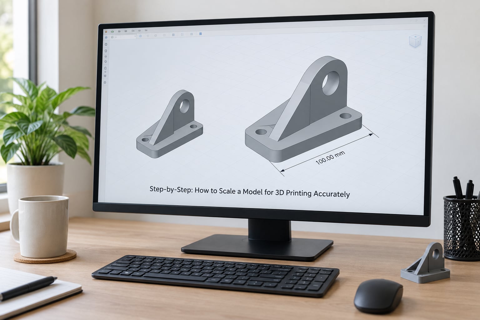
The workflow is six steps, and it works the same whether you are in a slicer, a mesh editor, or a parametric modeler: back up and confirm units, select the right geometry, enter a real target dimension, apply one uniform factor, inspect the features scaling will distort, then measure and export.
Before you type a number, write this down:
Scale factor = target dimension ÷ current dimension
Three worked examples that cover most cases:
- A 28 mm tabletop miniature that must match 32 mm official models: 32 ÷ 28 = 1.143, or 114.3%.
- A 20 mm tolerance cube that needs to be a 25 mm keyring blank: 25 ÷ 20 = 1.25, or 125%.
- A print that keeps coming out oversized, now fixed in the printer profile, so the model shrinks 10%: 0.9, or 90%.
Step 1: Back Up the Original Model and Confirm Its Units
Save a copy under a new name first. Then open your CAD or mesh program’s measurement tool and read the bounding box in X, Y, and Z. You are establishing two things: what unit system the file is authored in, and what the reference dimension is right now.
If you are unsure of the unit system, do not guess from the number. Scale the model to 100 mm tall in the program and look at the resulting bounding box. If the model is effectively life-size, the file is in millimeters. If it becomes a toy, the file was in centimeters or inches.
Step 2: Choose the Part or Geometry to Scale
Select only the object that needs to change. In a slicer, click the model in the canvas, not the build plate, and confirm only one object is highlighted. In Blender, select the object in the outliner and check the N panel dimensions. In a parametric modeler, scaling a feature resizes it relative to the sketch or constraints that drive it, which can move the whole part or fight the constraint solver.
For a multi-part assembly, select every body and apply the identical factor. Two mating pieces scaled by 1.14 and 1.15 no longer fit, and the gap is small enough that you will not see it in the preview.
Watch for linked or referenced geometry. Scaling a parent that drives a linked library part can rewrite the library file, which is a bad afternoon. Unlink or make a local copy first.
Step 3: Enter a Reliable Target Dimension
Pick one reference dimension that matters and enter its real-world target value: the overall height of a miniature, the outer diameter of a hole, the length of a replacement bracket, the bore of a bearing seat. Do not scale from a visual guess of how big it should look on screen. That habit is the single most common source of models that print at the wrong size.
Use a dimension that is easy to measure on the finished print. Overall height is good. A hidden internal feature is not. If the real object is a known standard, use that number rather than a rounded figure.
Step 4: Apply Uniform Scaling and Check the Scale Factor
Uniform scaling multiplies X, Y, and Z by the same factor, so every angle, ratio, and hole stays true. Non-uniform scaling uses a different factor per axis, which shears the geometry: circles become ovals, holes go out of round, and a cylinder stops being a cylinder.
| Method | Effect on proportions | Effect on holes and circles | When it is acceptable |
|---|---|---|---|
| Uniform scale | All proportions preserved | Holes stay round | Almost always |
| Non-uniform scale per axis | Stretched or squashed | Turned into ovals | Filling a build volume with a deliberately distorted decorative piece |
Apply a single factor and confirm the percentage the software reports matches your calculation. If it does not, something is off in the units or the selection.
Menu paths, by program:
| Program | Where the scale control lives | Notes |
|---|---|---|
| PrusaSlicer 2.8 and later | Right-click the object, choose Scale, then tick Uniform scale | The uniform box is off by default in some versions; typing one axis value only is the classic mistake |
| Ultimaker Cura 5.x | Select the object, click the non-uniform scale button on the toolbar, enter X, Y, and Z fields | Leave the mirror axes alone; check Uniform when you want a single factor |
| Bambu Studio and OrcaSlicer | Select the model, open the Transform panel, use the X, Y, and Z fields with the chain link engaged | Broken chain means per-axis scaling |
| Lychee and Chitubox | Select the object, open the Scale and Rotate panel, drag the uniform slider | Snap to 0.01 increments for resin work |
| Blender | Press S, type the factor, then Object > Apply > Scale | Never export with a non-unity object scale left unapplied |
| Tinkercad | Drag a corner handle while holding Shift | Fine for casual work, imprecise for tolerances |
| ViewSTL or Meshmixer | ViewSTL has a scale factor box; Meshmixer uses Transform then Scale | Good fallback when you want no install |
If you work in Blender, clear non-uniform object scale before anything else. Open the N panel and look at the object scale values under Transform. Anything other than 1.000 in one axis skews every subsequent operation, including the scale you are about to apply, and the distortion shows up as out-of-round holes long after you have forgotten the change.
After scaling, check the datum. Scaling around the object origin can leave the part floating, half-submerged in the build plate, or far off the bed. Drop it to Z = 0 and center it in X and Y before you export.
Step 5: Inspect Features That Scaling Can Distort
Proportions survive, but absolute feature sizes do not. Everything on your part has a new size after scaling, and some of it now falls below what your process can hold. This is where how to scale a model for 3D printing accurately stops being a numbers problem and becomes a geometry problem.
- Walls. A 1.2 mm wall scaled to 60% becomes 0.72 mm, which is under two extrusion widths on most FDM printers and will print weak or as a single gapped line. Most 0.4 mm nozzles need three perimeters, roughly 1.2 mm minimum.
- Holes for pins, shafts, and screws. These are the fit-critical features. Shrink a 6 mm bore by 40% and the pin that used to slide in now binds.
- Threads. Scaling a modeled thread does not produce a standard thread. The pitch changes, so the nut no longer matches. Model at final size or buy the thread as a standard insert.
- Snap fits, clips, and living hinges. Flexibility depends on the ratio of length to thickness. Halving both makes the part stiffer, and a snap fit that worked can snap in the wrong direction.
- Clearances and press fits. Scale the whole assembly by one factor or the gaps become uneven.
- Text and embossed detail. Under about 0.4 mm tall, raised lettering turns into a smear at typical layer heights. Deep engraving survives scaling down better than shallow relief.
- Supports and small protrusions. Features that barely existed can vanish or fuse to the layer below.
Two related limits. Scaling up is fine for dimensional size, but it exposes what was always there: the mesh was modeled at a certain resolution, and enlarging a scanned or sculpted model makes that resolution visible. Remeshing before you scale up, or uprescaling the texture and re-sculpting, avoids a soft result. And check the build volume before you commit, since a model scaled to 130% will not fit a bed it fitted on yesterday.
Layer height sets the floor on what survives. A 0.2 mm layer cannot represent a 0.15 mm step no matter how clean the mesh is. On a 0.4 mm nozzle, going below roughly half the nozzle diameter on layer height, under 0.2 mm, buys little and costs print time and first-layer reliability.
Step 6: Measure, Validate, and Export the Scaled Model
Measure several reference dimensions in the model, not just the one you typed. Check the scaled height, the width, and one hole or feature that has to fit something. If the three disagree with your targets by different amounts, the scale was not uniform or the units were wrong.
Run the program’s validation or repair pass. Manifold check, flipped normals, and self-intersections cause slicing artifacts that look like scaling errors but are not.
Export in the format your slicer expects, usually STL or 3MF, with the unit system set to millimeters. Then load it into the slicer and compare the reported dimensions against your targets before slicing. The slicer bounding box is the last digital check you get.
The final check is physical. Print a 20 mm tolerance cube or a calibration cross, measure it with calipers in X, Y, and Z, and compare against nominal.
Then close the loop properly, in this order:
- Measure the cube. Compare actual to printed, not to model.
- If X and Y are off in the same direction, adjust the XY steps per mm value in your firmware or slicer profile, then print again. Users on r/3Dprinting consistently recommend this before any slicer scale compensation.
- If Z is off, adjust Z steps per mm the same way.
- If the base is oversized but the top is correct, that is elephant foot: the first layer spreads under pressure from the nozzle. Enable elephant foot compensation or an initial layer horizontal expansion adjustment rather than scaling the model.
- If everything is uniformly swollen or shrunken, suspect flow rate. Over-extrusion is often mistaken for a scale problem; fix the extrusion and leave the scale factor at 100%.
For resin printers, add a shrinkage step instead. Machinists on home model engine forums apply a measured shrinkage factor of about 1.015 to resin prints to hit machining tolerances, but the number is specific to your resin and machine, so calibrate it with a test coupon rather than borrowing it.
Common Mistakes
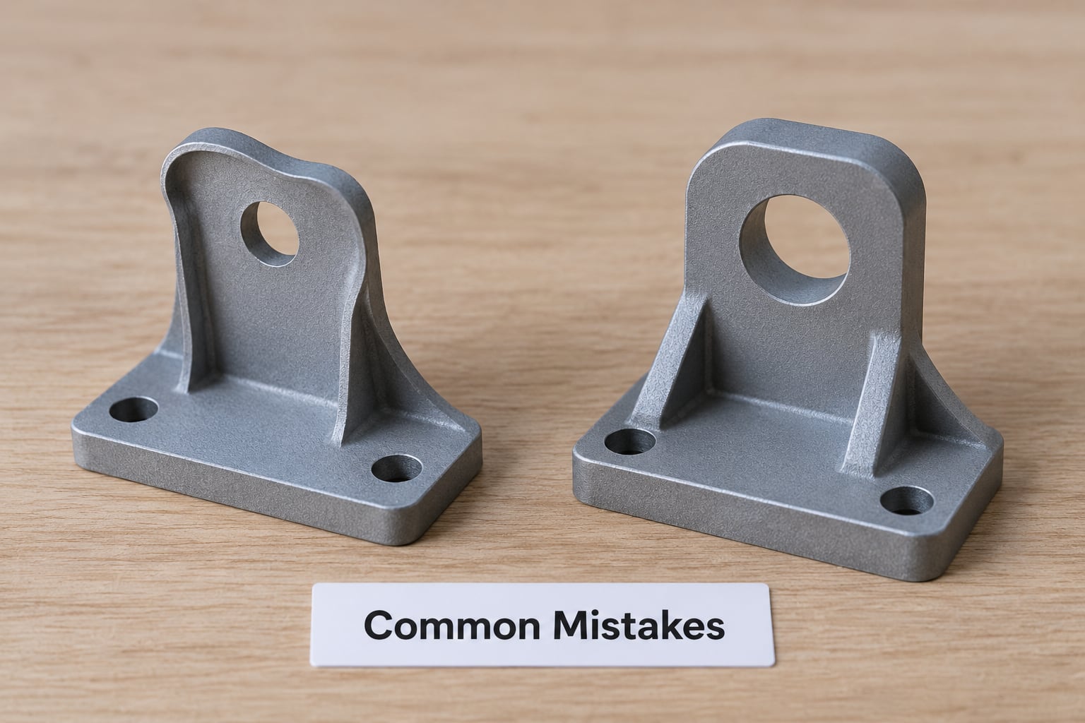
Almost every scaling problem is one of these, and each has a two-minute fix.
Scaling the whole assembly instead of one part
Everything moves, and mating relationships change. Select only the body that needs to change, and if several parts must move together, apply one identical factor to all of them in a single operation.
Typing the scale percentage from a visual estimate
Drop the percentage field and use the target-dimension field instead, entering the real measurement you want. The software computes the factor, and the numbers now match your intent.
Applying scale twice
Scaling 125% then 125% again gives 1.5625. Start over from the backup copy each time, or use a single operation with a computed factor.
Leaving non-uniform scale in Blender
Press S, type the factor, then Object > Apply > Scale. Check the N panel scale values read 1.000 on all three axes. Until that is done, every modifier and every export carries the skew.
Ignoring thin features when scaling down
Measure your smallest wall and smallest hole after scaling, not before. A wall under three extrusion widths and a snap fit scaled below half its original length are the two failures that show up most often.
Not rechecking dimensions after export
Reloading the exported file into the slicer and reading the bounding box costs a minute and catches unit mismatches, wrong selections, and a dropped third of the scale.
Fixing a printer problem with the scale slider
If the model is right and the print is wrong, the model is not the problem. Correct steps per mm, flow rate, and first-layer compensation, then re-measure. Scaling the file to hide a printer fault just moves the problem to the next model.
Forgetting the datum
After scaling, the part can end up below the build plate or off center. Set Z to 0 and re-center in X and Y, then confirm the slicer preview looks right.
Frequently Asked Questions
Can you scale up a 3D model?
Yes, and most CAD and slicing programs handle it with a single uniform factor. The size change is easy; the detail is not always preserved. Enlarging exposes the resolution the mesh was built at, so a scan or a low-poly sculpt can look soft or faceted at the new size. Remesh the file before scaling up, and check that the enlarged part still fits inside your printer’s build volume.
What are the differences between uniform and non-uniform scaling?
Uniform scaling multiplies X, Y, and Z by the same factor, so proportions, angles, and hole shapes stay exactly as designed. Non-uniform scaling uses a separate factor per axis, which stretches or squashes the part, turns circles into ovals, and shears holes out of round. For 3D printing, use uniform scaling unless you are deliberately distorting a decorative part.
Should I scale in the slicer or in CAD?
Scale in CAD or a mesh editor when the model needs to change permanently, when you are working on an assembly, or when you want the corrected file for other uses. Scale in the slicer for a quick one-off fit to your build volume, because the slicer never touches the source file. Many people keep the original model authoritative and treat slicer scale as a temporary override.
How do I fix non-uniform scale in Blender?
Select the object, open the N panel, and look at the scale values under Transform. If any axis is not 1.000, press S, type 1 to reset the proportions, then go to Object and choose Apply, then Scale. Confirm the values now read 1.000 on all three axes. Until the scale is applied, modifiers and exports inherit the skew and holes print out of round.
How do I make 3D prints more dimensionally accurate?
Calibrate before you compensate. Print a 20 mm tolerance cube, measure it with calipers in X, Y, and Z, then adjust the XY and Z steps per mm values in your firmware until the error is under 0.1 mm. Fix flow rate next, then address first-layer oversize with elephant foot compensation. Only if a uniform error remains should you apply a small scale factor in the slicer.
Why is my 3D print the wrong size when the model looks correct?
Four usual causes: extrusion flow running high or low, an oversized first layer from elephant foot, incorrect steps per mm in the firmware, or resin shrinkage on MSLA printers. Elephant foot makes the base measurably larger than the top, which points at first-layer pressure. A part that is uniformly off in every direction points at flow or steps per mm instead.
Conclusion
Confirm the units and record the current dimensions, pick one real-world reference dimension, apply a single uniform scale factor with the software, then measure the exported file in the slicer. After that, print a 20 mm tolerance cube and correct steps per mm, flow, and first-layer oversize before blaming the model again. Knowing how to scale a model for 3D printing accurately is a measurement loop, not a single slider.