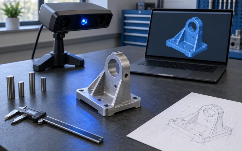
Reverse engineering a part from a 3D scan means capturing the part’s geometry as a mesh, then using that mesh as a dimensional reference to rebuild an editable, parametric CAD model you can change, machine or print. For most parts the job takes a few hours once the scan is captured, and nearly all the difficulty sits in two places: cleaning the mesh and rebuilding the surfaces the scanner could not see.
It matters because most replacement parts have no drawing and no original CAD file. Restorers, makers and manufacturing engineers all end up at the same bench, holding a physical part and needing geometry they can actually work with. Here is what to have ready, the order to work in, and the points where it usually goes sideways.
Table of Contents
- What You Need
- Step-by-Step: How to Reverse Engineer a Part From a 3D Scan
- Define the Part and Its Required Accuracy
- Prepare and Position the Part for Scanning
- Capture the 3D Scan from Multiple Angles
- Align, Register, and Clean the Scan Data
- Repair and Rebuild the CAD Model
- Validate the Reconstructed Part
- Export a Fabrication-Ready File
- Common Mistakes
- How to Choose Scan Software and CAD Tools
- How Accurate Does a 3D Scan Need to Be?
- Can You Reverse Engineer a Part From an Incomplete 3D Scan?
- Frequently Asked Questions
- What software is best for reverse engineering a part from a 3D scan?
- Can I convert a 3D scan directly into an editable CAD model?
- How do I fill missing areas and holes in a scanned part?
- How can I tell whether a reverse-engineered CAD model is accurate?
- Should I use a mesh file or a solid CAD model for 3D printing?
- How many scans do I need to capture a complete part?
- Conclusion
What You Need
Scan-to-CAD goes wrong more often from a missing tool than a missing skill. Work through this list before you switch the scanner on.
| Item | What it does in the job |
|---|---|
| The physical part | The dimensional reference. Keep it on the bench, because you will measure it again later. |
| A 3D scanner | Desktop structured light, a blue laser arm, or a photogrammetry rig. Match it to part size and surface finish. |
| Scan-processing software | Turns the raw point cloud into a usable triangle mesh in STL, OBJ or PLY. |
| A mesh cleanup tool | Blender, Meshmixer or MeshLab for removing floaters, noise and holes before CAD sees the data. |
| CAD with mesh import | Fusion 360, SOLIDWORKS or Onshape for alignment, cross-sections and solid modeling. |
| Reference measurements | Calipers and a micrometer for the dimensions a scan will not hand back cleanly. |
| A validation method | A way to check the finished model against the real part before you cut or print. |
Two of those matter more than most people expect. Without physical measurements, every gap the scanner missed turns into a guess. And without a validation step, a model can look perfect on screen and still sit a millimetre out on the one surface that matters.
Step-by-Step: How to Reverse Engineer a Part From a 3D Scan
Define the Part and Its Required Accuracy
Before scanning anything, write down what the part does and how close you actually have to get. A plastic trim piece for a restored car needs to look right. A bearing seat or a bolt pattern needs to be right. Those are different jobs with different amounts of work behind them.
Find the surfaces that carry the function: bearing bores, mounting faces, shaft seats, thread locations, mating flanges. Those get measured with calipers and built as real geometry. Everything else can stay close to what the scan captured.
List the areas the sensor will not see while the part is in one position. Deep pockets, blind holes, the underside of a flange, anything under an overhanging lip. Knowing that now saves the frustrating version of this job where you finish the model, open it up, and find a hole you have no way to dimension.
If you cannot say what tolerance the part has to hit, pause and find out. Printing a visual replica and making a working replacement follow different workflows, and finding out which one you are doing saves rebuilding the model later.
Prepare and Position the Part for Scanning
Dirt, oil and loose filings end up in the mesh as bumps you will spend an hour removing later. Degrease the part, brush off the debris, and let it dry fully.
Shiny and dark surfaces are the other classic failure. Chrome, bare aluminium, polished paint and black plastic either return holes or a smeared surface. Those areas need a matte coating, applied in thin passes so you do not fill a small hole with primer. Small adhesive markers are the alternative when you only need to locate a feature you cannot see through.
Set the part on a matte, high-contrast surface rather than a polished bench top or a black cloth, since both confuse structured light scanners. Angle it so the sensor reaches the areas you care about, and when something is permanently in shadow, plan a second setup from another direction rather than tilting the part until the shadow moves.
Check whether the sensor can physically resolve the detail you need. A scanner with 0.1 mm capability will not capture a fine thread, and no amount of cleanup brings that detail back.
Capture the 3D Scan from Multiple Angles
Scan from overlapping positions and keep the overlap generous, roughly a third of the part shared between neighbouring passes. That overlap is what registration uses to stitch passes together, and thin overlap is the usual reason a join drifts or tears open.
Move closer for small features rather than zooming in afterwards. Sharp edges, threads and small holes want a short working distance and a steadier pass. One focused scan of a feature beats ten attempts to sharpen it in software later.
Record measurements as you go: overall length, bore diameters, main plate thickness, hole centre spacing. Also make sure one identifiable feature appears in several passes, because that shared landmark is what gives the software something to align on.
Finish with a repeat pass from a different direction to confirm the surfaces that gave you trouble. It costs a couple of minutes and catches gaps while the part is still on the stand.
Align, Register, and Clean the Scan Data
Registration stitches the passes into a single point cloud or mesh. Work from coarse to fine, inspect each join, and delete any pass that pulled the surface out of line instead of trying to correct it in software.
Then clean the mesh in this order: remove floating geometry and disconnected shells, fill small holes, strip noise with a mild smoothing pass, and decimate the polygon count down to something your CAD tool can section quickly.
Smoothing is where good data gets ruined. Keep the pass light and check a sharp edge afterwards, because aggressive smoothing rounds the very edges the scan worked to capture. Set a numeric limit on the filter rather than dragging the slider until it looks right.
This step is the one most guides skip and the one practitioners complain about most. A dense scan with millions of triangles makes sectioning painfully slow in Fusion 360 or SOLIDWORKS, and users on r/SolidWorks describe needing paid add-ins just to handle mesh density natively. Blender and Meshmixer come up again and again on r/3DScanning for exactly this cleanup pass, with MeshLab the usual free option.
Once the mesh is clean, check it before modeling. Look for self-intersections and non-manifold edges, confirm the shell is closed if you plan to print it, and delete stray geometry from the floor or the fixture you scanned alongside it.
Repair and Rebuild the CAD Model
Keep the original scan file untouched and work on a copy. You will come back to it for comparison, and the first cleanup pass always reveals something you want to recheck.
Import the mesh and align it to a coordinate system. Put a datum plane on the largest flat face, a second plane along the main axis, and an axis through a hole or shaft centre. Well-placed datums make every later feature land in the right place on its own.
Next, slice the mesh into cross-sections and sketch on them. Each section gives you a flat profile to trace with real dimensions, which is far more accurate than eyeballing a 3D view. Take a section at every feature height, plus a couple either side of a fillet so you can see where the tangency starts.
Build parametric features rather than lumps. A circular profile revolved around the shaft axis gives you a solid with a diameter you can edit later. Extrusions, lofts and sweeps cover most of the rest. Anything parametric gets corrected in seconds when validation finds an error, and that is the difference between a model you iterate on and one you rebuild from scratch.
Add the details the scan handles badly. Countersinks, counterbores, threads and chamfers come from a callout and a measurement rather than from the mesh, because a scanned thread is a lumpy cone and a scanned chamfer is a fuzzy band. Locate threaded holes by measuring the centre positions on the physical part instead of trusting the mesh, which is the reliable way to place them.
For areas the scanner never saw, rebuild from design logic wherever the part gives it to you. A four-hole pattern is almost certainly symmetric about its centre, so two dimensions define all four. A blind hole opposite a through hole is usually a repeat of the same callout. Where no logic applies, take the measurement and write it into the model, then note the assumption so whoever opens the file knows it was inferred rather than scanned.
That last habit is what design intent recovery really comes down to. Ask how the part was originally made. A turned feature shows concentric tool marks, a milled pocket leaves a consistent corner radius, and a cast body has draft on every vertical face. Those clues tell you which dimensions are the driving ones and which are just consequences.
Validate the Reconstructed Part
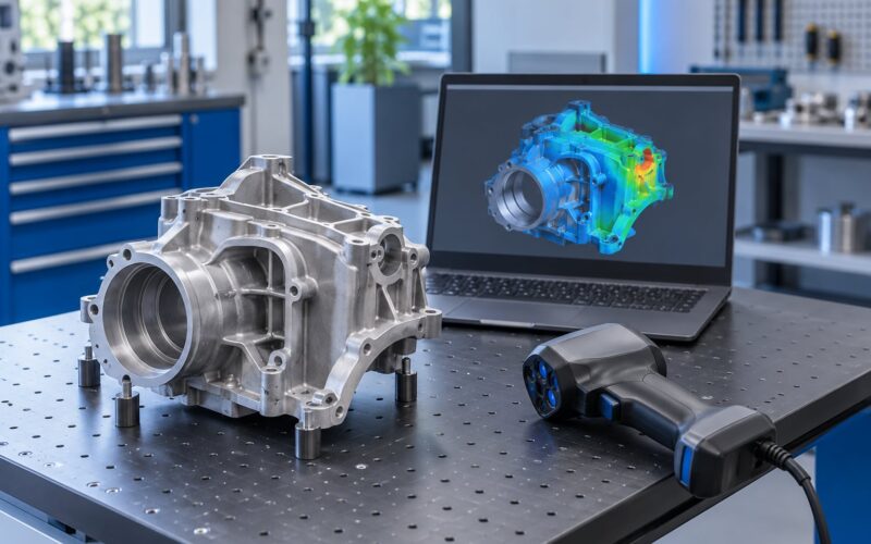
Compare the model with the scan before trusting either one. Every serious CAD package will run a deviation check that produces a color map, where green sits inside your tolerance band and red sits outside it.
Read it carefully. A uniform red field usually means the mesh and the model are offset from each other, not that the shape is wrong, so fix the alignment first. What matters is isolated red and blue patches, because those mark features that are genuinely mis-modelled.
Then check specific numbers with calipers on the physical part and compare them against the model. Measure the critical surfaces you listed at the start: bore diameter, plate thickness, hole spacing, overall envelope. Section views through the model catch errors that a shaded view hides completely.
If the part mates with something, print or machine a quick test piece and check the fit. Once you have a printed version, re-scan it and compare that scan to the original. That second loop is the one that catches print compensation and shrinkage, and it tells you whether the tolerances you assumed were realistic.
Export a Fabrication-Ready File
Pick the format for the downstream job. STEP carries exact geometry and stays editable, which makes it the right choice for machining, further design or sending to a supplier. STL is universal for slicing, and 3MF carries scale and size more reliably for printing. OBJ and PLY are for viewing and for passing cleaned mesh data to another tool.
Before exporting, confirm the scale is correct and that the file is in millimeters. A mesh that arrives at the wrong size is one of the most common beginner problems, and it is far easier to fix the source model than to scale a finished file by hand.
For printing, check the shell is watertight, that no tiny stray shells float nearby, and that the geometry is thicker than the printer’s minimum wall. For machining, model the tool access and confirm every fillet is larger than the cutter radius, or the job will not run.
Common Mistakes
| Symptom | Likely cause | Fix |
|---|---|---|
| Holes in shiny or black areas | Light reflecting off the surface instead of returning to the sensor | Coat with matte scanning spray, add markers, scan from closer range |
| Model arrives at the wrong size | Scale or unit settings wrong in scan software | Measure a known dimension, correct scale at the source, re-export |
| Sections slow down or crash CAD | Mesh polygon count far too high | Decimate the cleaned mesh before importing |
| Edges and threads look rounded | Smoothing filter applied too strongly | Lower the smoothing threshold and re-run, or re-scan the feature |
| Model will not sit in its assembly | Component detail guessed or misaligned | Split the scan into individual components and remodel each one |
| Threads and holes distorted | Sensor cannot resolve the feature | Model them from a callout and a physical measurement |
| Deviation map is red everywhere | Mesh and model offset, not mis-shaped | Re-run alignment and check the coordinate system |
| Looks right but will not fit | Everything traced from mesh, nothing measured | Take caliper readings on critical features before modeling |
How to Choose Scan Software and CAD Tools
Three distinct jobs sit between the scanner and the finished model, and it helps to know which one you are buying software for. Scan-processing turns the point cloud into a mesh. Mesh editing handles cleanup. CAD does the modeling. Tools that cover all three exist, but each one is strongest at a different job.
| Job | Free options | Paid options |
|---|---|---|
| Scan processing | Scanner vendor software, CloudCompare | PolyWorks, Geomagic Control X |
| Mesh cleanup | Blender, Meshmixer, MeshLab | Geomagic Wrap, XTract3D |
| Mesh to surface | Blender, FreeCAD | Geomagic Design X, QUICKSURFACE, Mesh2Surface |
| Parametric modeling | FreeCAD, Onshape, Fusion 360 for personal use | SOLIDWORKS, Fusion 360 commercial, Inventor |
A free route exists and it is not a dead end. Scan, clean in Blender, and model in Fusion 360 or Onshape covers most one-off jobs. You give up the automatic surfacing that Design X and QUICKSURFACE do well, and you do more manual work up front.
Reach for auto-surfacing when the geometry is organic, worn or irregular, and sketch manually when the part is mostly planes, cylinders and symmetric patterns. Auto tools give you a dense surface that matches the scan but is awkward to edit, which defeats the purpose if you plan to change the part. The same trade shows up in r/3DScanning threads: dedicated reverse engineering packages for organic surfacing, native CAD for mechanical parts.
Decide what the final output has to be before choosing software. If the model only needs to be printable, a cleaned mesh plus a free CAD tool is enough. If it has to be machined, edited later or dropped into an assembly, you need a real parametric model, and that changes the whole software question.
How Accurate Does a 3D Scan Need to Be?
Accuracy is set by what the part does, not by the scanner’s spec sheet. A visual replica needs very little. A part with a running bearing needs the bore sized correctly and the face flat. A mating bolt pattern needs hole positions close enough to take a fastener without reaming.
Typical published specifications give a rough guide. Desktop structured light scanners usually land near plus or minus 0.1 mm on a well-prepared matte part, while metrology-grade blue laser arms work in the plus or minus 0.02 mm to 0.05 mm range. Both figures assume a controlled setup, not a dusty workshop bench.
What actually moves the usable accuracy is scanner calibration, working distance, surface finish, how steadily the part sits, and how carefully the passes were registered. A modest scanner used carefully on a matte, rigid part regularly beats an expensive one used badly.
Community experience sets useful expectations too. Users on r/3DScanning and r/CNC scanning bolts, nuts and other small hardware report that around 0.1 mm is already finer than they can exploit, and say you would be better off drawing those from a callout. Past that resolution, surface finish, noise and modeling judgment dominate, so a finer scanner rarely rescues the part you are struggling with.
Set the target before scanning, not after. A tenth of a millimetre is generous for a printed replacement and useless for a press fit.
Can You Reverse Engineer a Part From an Incomplete 3D Scan?
Yes, in most cases. Scans come out incomplete far more often than unusable, and the gaps fall into three groups that each need different treatment.
The first group is inferable from the part itself. A missing section on a symmetric part follows from the side you can see. A repeated pattern of holes or ribs continues from the ones present. A hidden face behind a flange usually lies on a plane established somewhere else on the part.
The second group needs a number. Thread depths, counterbore diameters, internal chamfers, the true width of a face the scanner only grazed at a glancing angle. Take those from calipers or a micrometer on the physical part, or from a second scan with the part repositioned. Here, measurement is not optional.
The third group is genuinely unknowable from geometry. Internal wall thicknesses, material spec, heat treatment and original tolerances are not in the scan. Decide them from how the part functions and mark them as assumptions in the file so nobody downstream treats them as recovered fact.
One warning: patching a hole in the mesh to make it watertight is a printing trick, not a modeling one. It lets a slicer produce a solid, but it invents geometry. Model the feature properly instead.
Frequently Asked Questions
What software is best for reverse engineering a part from a 3D scan?
For most one-off jobs, scan with the scanner’s own software, clean the mesh in Blender or Meshmixer, then model in Fusion 360 or Onshape. Geomagic Design X and QUICKSURFACE earn their cost on organic or worn surfaces where automatic surfacing saves days. Match the tool to the part: planes, holes and cylinders are usually cheaper to sketch by hand than to auto-surface.
Can I convert a 3D scan directly into an editable CAD model?
Not directly. A scan is a triangle mesh, and CAD works with features such as sketches, constraints, revolves and extrudes. What you can do is import the mesh, align it, slice it into cross-sections, and trace those sections as dimensioned sketches, which produces a fully parametric model. Automatic mesh-to-CAD gives you a surface, not features, so it is editable but not parametric.
How do I fill missing areas and holes in a scanned part?
Small holes in the mesh you fill during cleanup in Blender, Meshmixer or MeshLab, so the surface is continuous for sectioning. Areas the scanner never saw are a different job: rebuild them in CAD from symmetry, repeated patterns, or a physical measurement. Patching the mesh is fine for printing but invents geometry, so never let a patched surface become the basis of a machined feature.
How can I tell whether a reverse-engineered CAD model is accurate?
Run a deviation comparison between the CAD model and the original mesh and read the color map, where green sits inside your tolerance band and red sits outside it. Then measure critical features on the physical part with calipers and compare them to the model. A uniform red field usually means the mesh is offset, while isolated red and blue patches mark features that are genuinely mis-modelled.
Should I use a mesh file or a solid CAD model for 3D printing?
If you only need a printed part, a cleaned watertight mesh is enough and saves hours of modeling. If the part has to change, mate with other components or get machined later, build the solid model and export the mesh from it. The solid is also easier to validate, because you can measure named features instead of guessing at a scanned surface.
How many scans do I need to capture a complete part?
Enough to cover every surface with generous overlap, roughly a third of the part shared between neighbouring passes. A simple flat part takes a handful of passes. A complex casting or an assembly with deep pockets takes many more, and a second setup from another direction often beats extra passes from the same angle. Repeat one feature across several passes so registration has a landmark to align on.
Conclusion
Start by writing down what the part has to do and which dimensions must be right, because everything after that gets easier once you know which features you cannot afford to guess. Then scan with generous overlap, register the passes, clean the mesh, and decimate it before it goes into CAD.
Build parametrically, restore whatever the scanner missed from symmetry or a caliper measurement, and note every inferred dimension. Then run a deviation check against the original scan and re-scan a printed test piece before you commit to metal. That loop is what turns a scan-to-CAD model into a part that actually fits.