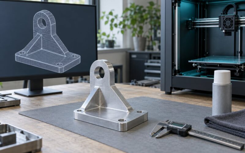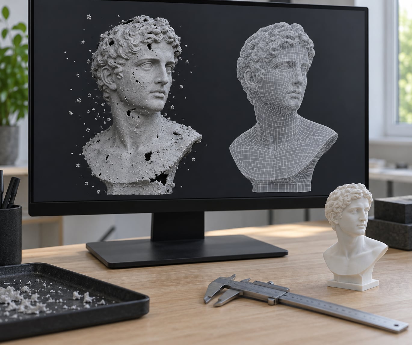
A raw 3D scan is a record of what a camera or laser saw, not a solid object. It arrives full of holes, floating speckle, inverted normals and stray geometry that will either stop your slicer outright or produce a print with missing walls. Learning how to clean up a 3D scan mesh for printing is mostly a matter of working through the defects in a fixed order, checking your result after each pass, and never touching the original file again.
Most first-time cleanups take 30 to 90 minutes for a tabletop-sized scan. The awkward part is not the clicking, it is knowing which of the available operations to run and when.
Table of Contents
- What You Need
- Step-by-Step
- 1. Import the Scan and Check Its Scale
- 2. Inspect the Mesh and Identify Defects
- 3. Remove Loose Parts, Duplicate Geometry, and Scan Noise
- 4. Repair Holes, Broken Edges, and Problem Areas
- 5. Fix Winding, Normals, and Surface Orientation
- 6. Make the Mesh Watertight and Manifold
- 7. Simplify Without Losing Important Detail
- 8. Add Print Geometry and Export the Final Mesh
- Common Mistakes
- Frequently Asked Questions
- What is the best software for cleaning a 3D scan mesh for printing?
- How do I fix a non-manifold 3D scan mesh?
- Should I close every hole in a scanned 3D model?
- How much smoothing does a 3D scan need before printing?
- When should I decimate or remesh a 3D scan?
- How do I know whether a cleaned scan mesh is printable?
- Conclusion
What You Need
Before you open anything, gather five things:
- The original scan file, untouched. Keep the raw STL, OBJ, PLY or 3MF exactly as the software produced it. Duplicate it, work on the copy, and never export over the source.
- Mesh-editing software. Blender 4.x is what the steps below use, but Meshmixer, MeshLab, Fusion 360 Mesh Workspace, Netfabb and Meshmagic all cover the same ground with different menu names.
- A known measurement to check scale against. A caliper reading, a printed plan dimension, or a dimension you can verify from a drawing. Without one, you cannot tell whether the mesh is in millimeters or meters.
- Your printer or slicer settings. Layer height, nozzle diameter and process type (FDM, resin, powder bed) determine which cleanup decisions are safe.
- Optional but useful: Blender’s 3D Print Toolbox add-on, a mesh inspector such as Netfabb Basic or Meshmagic, and a second pair of eyes for the bite-mark judgement calls.
Menu names shift between versions and the instructions here follow Blender 4.x, where Repair, Clean Up and Normals live under the Mesh menu in Edit Mode. Other packages use equivalent operations under different labels.
Here is how the common options compare, since tool choice changes which repairs feel easy:
| Tool | Cost | Learning curve | Strongest at |
|---|---|---|---|
| Blender 4.x | Free | Moderate | Full control: normals, sculpt-mode noise work, decimation, Solidify, 3D Print Toolbox checks |
| Meshmixer | Free | Low | Beginner-friendly hole closing and reduction, but development has effectively stalled |
| MeshLab | Free | Low to moderate | Statistical inspection, isolated-piece removal, quadric decimation on very large meshes |
| Fusion 360 Mesh Workspace | Free for personal use | Moderate | Mesh Wrap for stubborn holes plus a smooth move into CAD for reverse engineering |
| Netfabb | Freemium | Low | Industrial-grade automated repair and hard validation of the finished solid |
| Meshmagic | Paid | Low | Fast automated repair and remeshing on scans with millions of triangles |
Meshmixer still gets recommended constantly because it is simple, and that simplicity is real. Just know its development has slowed to the point that long-time users are moving to Blender or Meshmagic, and pick your tool accordingly before you build a habit.
Step-by-Step
1. Import the Scan and Check Its Scale
Import the scan and leave the original untouched. In Blender, use File > Import for STL, OBJ, PLY or 3MF, and immediately save the result under a new name such as scan_work.blend before you do anything else.
Now check scale. Switch to the Item properties and read the dimensions, then compare one edge to a measurement you trust. A scan that should be 180 mm long showing as 180 units is fine; showing 180000 units means you have a unit mismatch that will silently ruin every downstream step, including decimation and wall thickness.
Fix scale before any repair work, not after. Scaling later in the process re-introduces floating-point error and can reopen seams that were perfectly closed.
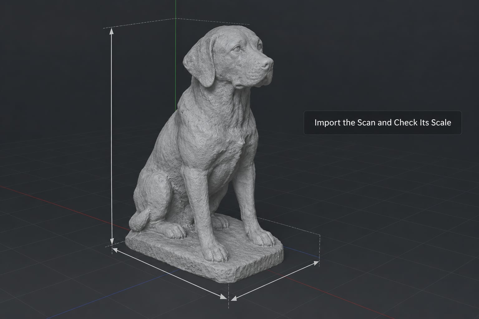
Success check: the reported dimensions match your reference measurement, the object sits in the correct place relative to the origin, and the original file is still byte-for-byte unchanged.
2. Inspect the Mesh and Identify Defects
Put the mesh in Edit Mode and look at it properly. Wireframe view exposes loose geometry, face mode shows holes and shading artefacts, edge mode reveals the problem edges, and the statistics panel in the viewport header gives you vertex, edge, face and triangle counts.
You are looking for six defect classes. Non-manifold edges are edges shared by more or fewer than two faces, which is the single most common reason a slicer refuses a file. Holes and gaps appear where the scanner could not see, usually in crevices and under overhangs. Inverted normals are patches shaded as if lit from the wrong side. Floating islands are disconnected shells and speckle from photogrammetry. Duplicate geometry is coincident or nested surfaces. Internal faces sit inside the solid, and zero-area faces contribute nothing but errors.
Write down what you actually see before you start fixing. Users who skip this step end up running merge and dissolve operations at random and making the mesh worse, which is the most common complaint in the Blender and photogrammetry communities.
Success check: you can name the defects in your specific scan, and you have a count for how many separate shells exist.
3. Remove Loose Parts, Duplicate Geometry, and Scan Noise
Isolate the object you actually want first. In Edit Mode, hover over the intended mesh and press L to select linked geometry, then invert the selection with Ctrl+I so the debris is selected instead. This single habit is what stops you from deleting the scan you spent a day capturing.
Then work in order. Use Select > All by Trait to isolate loose parts and non-manifold geometry, or in MeshLab run the isolated-piece removal filter with a diameter that matches the speckle you see. Merge coincident vertices with M > Merge by Distance using a merge distance smaller than your smallest real feature, typically 0.001 to 0.01 for a millimeter-scale scan. Run Degenerate Dissolve to strip zero-area faces, and Limited Dissolve to collapse planar detail you do not need.
Hold off on heavy smoothing. Surface noise is better handled deliberately in step 7, because smoothing applied now will soften edges that later steps depend on.
Success check: selecting linked geometry now returns the whole model, and the triangle count has dropped noticeably with no visible change to the surface.
4. Repair Holes, Broken Edges, and Problem Areas
Work hole by hole rather than firing a global fill. In Edit Mode, switch to vertex select, box-select the boundary loop of a hole and press F to fill it. For a long thin gap, use Edge > Bridge Edge Loops instead. For a small puncture where a triangle will not span the gap, use F with the nearest edge loop selected.
Blender 4.x also offers Mesh > Clean Up > Make Manifold, which attempts a broad automated repair in one pass. It is worth trying on a duplicated copy, but inspect the result closely: it will happily bridge across a real opening such as a handle hole or a gap between fingers.
For a scan too damaged to patch locally, a voxel remesh is a legitimate escape hatch. Set the voxel size to roughly half your smallest detail you care about, remesh, and accept that everything finer than that size is now gone. Use it on organic subjects, never on a mechanical part where edges are the point.
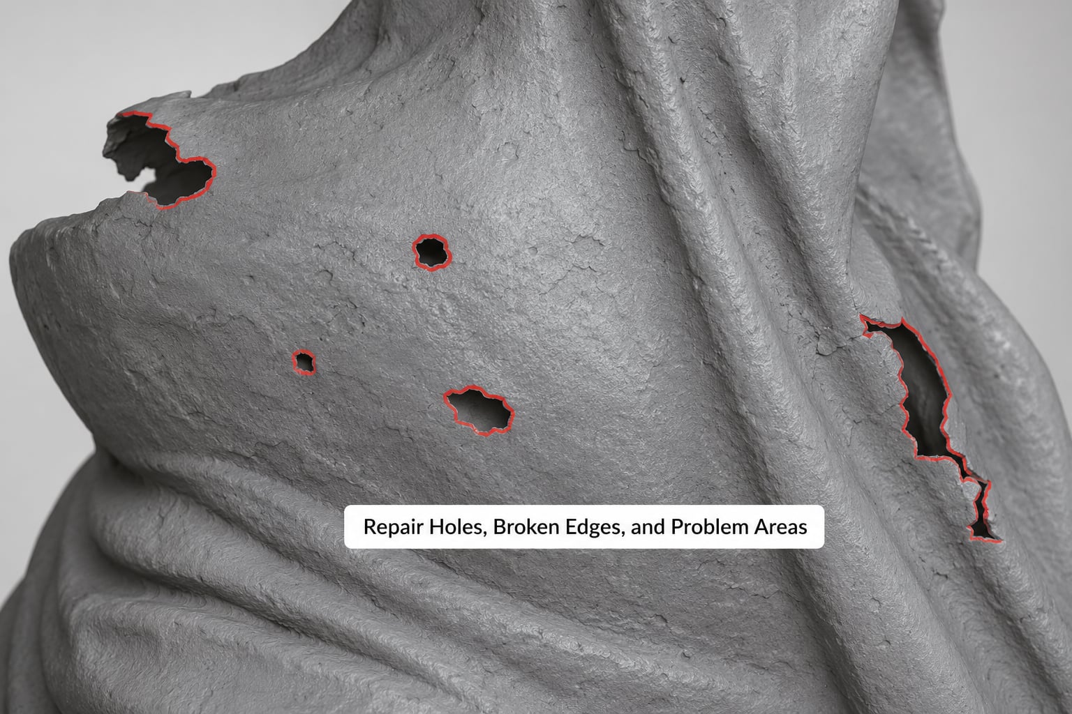
Success check: select boundary edges only (Select > All by Trait, Boundary) and the selection comes back empty.
5. Fix Winding, Normals, and Surface Orientation
Exit Edit Mode and recalculate normals outward with Mesh > Normals > Recalculate Outside. If part of the mesh flips the wrong way afterwards, the usual cause is a flipped or duplicated shell rather than bad face data, so hunt that down rather than flipping faces by hand.
Then verify the result in solid view. Shading should be continuous and lit from the direction you expect, and a translucent or wireframe-over-solid display should not show the surface back to front anywhere.
A reliable visual test: enable backface culling in the viewport shading options. Any surface that disappears when you orbit was facing inward. For thin-shelled scans this is the moment to add a Solidify modifier with an even thickness and offset set to zero, which turns a single surface into a printable shell rather than a zero-thickness plane.
Success check: the model reads as one solid body in solid shading, with no patches of inverted shading and no visible interior surfaces.
6. Make the Mesh Watertight and Manifold
A watertight mesh is a closed manifold solid: every edge is shared by exactly two faces, there are no boundary edges, no face with more than two faces on an edge, and no internal shell. If you get all four, your slicer will stop complaining about non-manifold geometry.
Run the check rather than assuming it. Blender’s 3D Print Toolbox sidebar gives you a live list of intersections, non-manifold edges, loose geometry and flipped normals, and Mesh > Clean Up > Make Manifold is the one-click attempt at the stubborn cases. When an automatic repair leaves a bad region behind, the pattern that works is to select the offending area, delete it, fill the opening, and stitch the surrounding surface to the new patch.
Self-intersections are a separate problem from non-manifold edges and slicers often flag them separately. They matter most on thin organic shapes where opposite sides of the scan collapsed together; separating them by hand beats any automated tool.
Success check: the analysis panel reports zero non-manifold edges, zero loose parts and zero flipped normals, and the volume calculation returns a positive number that roughly matches the real object.
7. Simplify Without Losing Important Detail
Simplify last, after the mesh is clean, because every repair operation becomes slow and fragile on a multi-million-triangle file. This is the part most guides get backwards: decimate a working copy to something manageable early, clean that, then apply the full-resolution result.
Calculate a target rather than guessing. Divide the surface area by (layer height x nozzle width) to get an order-of-magnitude triangle target, then add a factor of two to three for curvature. A scan roughly 200 mm across at 0.2 mm layer height and 0.4 mm nozzle lands in the low hundreds of thousands of triangles for a clean print; anything in the millions is wasted detail your nozzle cannot express.
The three reduction tools behave very differently, and choosing the wrong one is where people lose their detail:
- Decimate modifier preserves the overall shape and is the safe default for scans you want to keep faithful.
- Voxel remesh gives a perfectly uniform, guaranteed-manifold result but rounds off every edge and embossed detail below the voxel size.
- Quadric remesh or retopology produces a clean low-poly shell, ideal when the print only needs the outer form, but it discards all surface capture detail by design.
Success check: the model still matches its original proportions at a glance, and the triangle count is comfortably inside what your slicer handles without stalling.
8. Add Print Geometry and Export the Final Mesh
Give the scan a printable wall thickness. Anything thinner than two to three extrusion widths will simply not exist in the print, so either add a Solidify modifier or scale the model up until the thinnest real feature clears that floor.
Apply every modifier rather than leaving them live, then export. STL is the universal choice and is unitless, which is why scaling bugs happen there. 3MF carries units and colour and is the better option when your workflow supports it. Either way, confirm the export settings use scene units and that the object is at the world origin with no leftover rotation, because a model 40 mm off its intended position wastes a build plate.
Load the exported file into your slicer as the final check. Slice it, look at the preview, and confirm there is solid material where you expect it and thin air where the scan had a hole you meant to keep.
Success check: the slicer imports with no error, the preview looks correct, and the model fits inside your printer’s build volume.
Common Mistakes
Almost every ruined scan cleanup traces back to one of these:
- Closing holes that are real features. A gap between fingers or a handle opening looks identical to a scanner dropout. Check the original photographs or re-scan that area before you fill anything structural.
- Over-smoothing. Repeated smooth operations dissolve the surface texture that made the scan worth capturing. Smooth once, with a low factor, and only on the regions that read as noise.
- Filling the entire interior. A solid mesh should be a shell, not a ball of geometry. Internal faces left behind by fill operations cause slicer warnings and can produce hollow or blobby results.
- Ignoring scale. This is the mistake that costs the most time, because everything downstream is built on a wrong measurement and the error only shows up at the print stage.
- Insufficient wall thickness. A watertight mesh with 0.3 mm walls slices perfectly and prints as nothing. Thickness is a design decision, not a cleanup step you can skip.
- Assuming closed means printable. A closed mesh can still be self-intersecting, undersized for your nozzle, floating off the build plate, or have overhangs your process cannot support.
- Working destructively on the only copy. Duplicate first, always. There is no undo across an export.
Before you export, run this pre-flight list: no boundary edges, no non-manifold edges, no loose parts, no flipped normals, no self-intersections, wall thickness above two extrusion widths, minimum feature size above your nozzle diameter, model inside the build volume, and a clean slice preview.
If your slicer still complains, match the message to the fix: “non-manifold edges” means step 6 is unfinished; “object has no volumes” means normals are inverted or an internal shell is swallowing the solid, so go back to step 5; “model is outside the build volume” is a scale or position problem from step 1, not a mesh defect.
Frequently Asked Questions
What is the best software for cleaning a 3D scan mesh for printing?
Blender 4.x is the strongest all-rounder because it covers every repair operation, adds the 3D Print Toolbox for verification, and costs nothing. Meshmixer is easier to learn but its development has effectively stopped. MeshLab handles very large meshes well, while Netfabb and Meshmagic automate the fiddly repair work for a fee. Pick one and learn its menu paths rather than switching tools mid-project.
How do I fix a non-manifold 3D scan mesh?
Start by selecting all non-manifold edges with Select, then All by Trait in Blender, and look at what kind you have. Edges with only one adjacent face are boundary edges you can fill or bridge. Edges with three or more faces mean duplicated or overlapping geometry, so merge by distance and remove the redundant shell. For stubborn cases, isolate the region, delete it, fill the opening, and stitch the surface back together.
Should I close every hole in a scanned 3D model?
No. Close the holes that are scan artifacts, but leave holes that exist on the real object, such as a handle opening, a gap between fingers, or a vent. Filling a real opening changes the design and often looks wrong on the print. Judge each hole against reference photographs of the subject, and when a hole is ambiguous, rescan that area with more overlap rather than guessing.
How much smoothing does a 3D scan need before printing?
Enough to knock down speckle, and no more. A single low-factor smooth pass on the noisy regions usually does it. Repeated smoothing flattens genuine surface texture and rounds off edges, which is the detail you captured the scan to preserve. For photogrammetry bite marks, smoothing alone will not help, since those are stitching errors that need sculpt-mode work or a local remesh.
When should I decimate or remesh a 3D scan?
Decimate a working copy early, because repair operations crawl on a file with millions of triangles, then clean that copy and apply the result. Use decimation to reduce density while keeping the overall shape. Choose voxel remeshing when you need a guaranteed manifold result and can accept losing detail below the voxel size. Use quadric remeshing or retopology only when the outer form matters and the surface capture does not.
How do I know whether a cleaned scan mesh is printable?
Check four things in order: no boundary or non-manifold edges, no flipped normals, wall thickness at least two to three extrusion widths, and smallest features larger than your nozzle diameter. Then confirm it in the slicer. A clean slice preview showing solid material where the object should be and none where the scan had a deliberate opening is the real test.
Conclusion
Cleaning up a 3D scan mesh for printing follows a fixed order: import and check scale, catalogue the defects, strip floating parts and duplicates, close holes, recalculate normals, make the mesh watertight and manifold, decimate, then add wall thickness and export. Deviating from that order is what makes cleanups go wrong, because each stage depends on the one before it being correct.
Start with three things today: duplicate the raw scan so the original is safe, check the mesh dimensions against a real measurement, and spend five minutes cataloguing exactly which defects you have before running a single repair command.