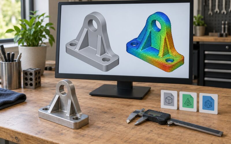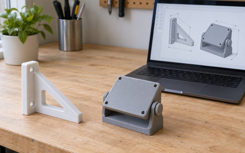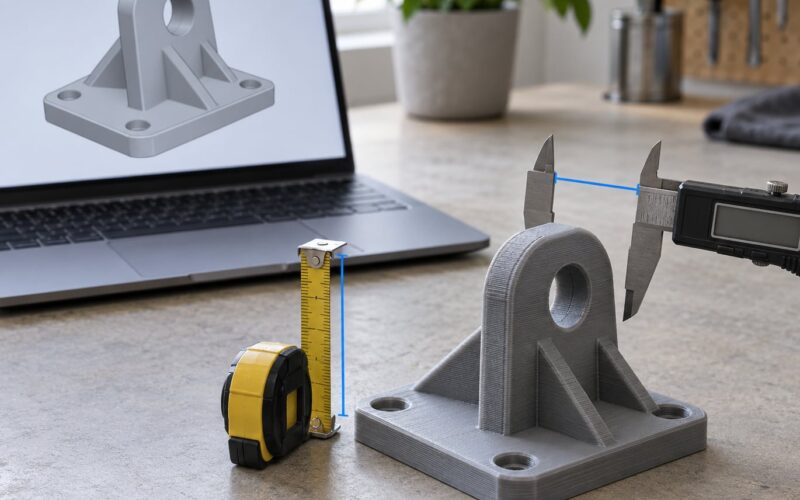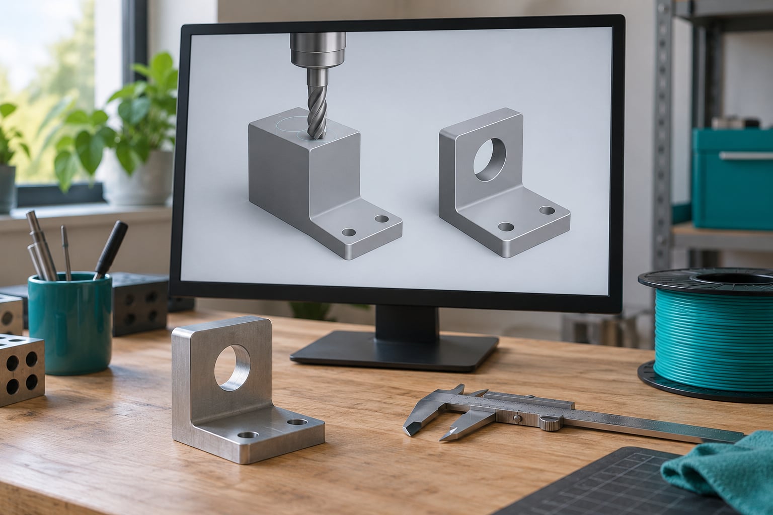
Boolean operations are how you turn simple shapes into a real part: union merges two solids into one, difference cuts the volume out of one, and intersection keeps only the overlap. Learn to use boolean operations in CAD for printable parts and you can cut a mounting hole, hollow a housing, or join a bracket and a boss without modeling any of it by hand.
The hard part isn’t the click. It’s the geometry going in. A Boolean only works when both bodies are closed solids that genuinely overlap, and when they don’t, the result comes back empty, inverted, or full of internal faces that make the slicer produce a hollow print. This guide walks through the whole sequence, from preparing the solids to exporting a watertight file, with the exact menu paths for the packages most people use. The underlying logic is the same across every package, even though the menu names differ.
Budget about 20 minutes for your first successful cut and an hour for a part you’ll actually trust. The skill scales fast once you understand why a failure happened rather than just retrying.
Table of Contents
- What You Need
- Step-by-Step: How to Use Boolean Operations in CAD for Printable Parts
- Create or Import Your Base Geometry
- Choose the Right Boolean Operation
- Apply and Inspect the Boolean Result
- Repair, Simplify, and Export the Printable Part
- Common Mistakes
- Frequently Asked Questions
- Which CAD software is best for boolean operations on 3D-printable parts?
- Should I do boolean operations in CAD or in my slicer?
- Why does my boolean union keep failing?
- How do I fix non-manifold geometry after a boolean?
- Do I need a manifold, watertight model before 3D printing?
- Conclusion
What You Need
You need four things before the first operation: a CAD package, valid solids, a target print process, and a way to check the result.
- A CAD package. Blender, Fusion 360, FreeCAD, Tinkercad, OpenSCAD, Rhino 3D, Onshape or SolidWorks all do Booleans; only the menu path differs. Any of them will work for the workflow below.
- Valid base geometry. Two closed solids that overlap, either modeled from primitives or imported and converted.
- A target process. FDM, resin or SLS each react differently to thin walls and internal faces, and that changes how much clearance you leave.
- A slicer with mesh analysis. Every major slicer flags non-manifold edges and open boundaries on import. That report is your final checkpoint.
If you’re starting from downloaded models, do the geometry check in this guide before you open your slicer. It takes a minute and it saves you the most common reason a print fails halfway.
Step-by-Step: How to Use Boolean Operations in CAD for Printable Parts
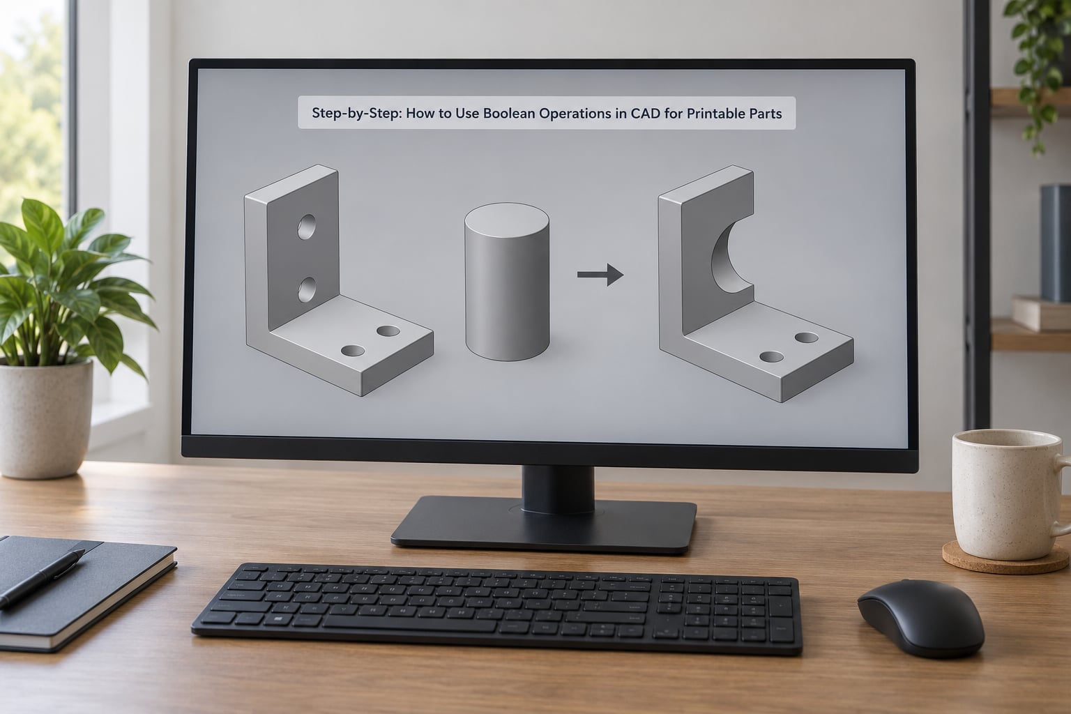
Create or Import Your Base Geometry
Start with solids that are closed — every edge bounded by exactly two faces, with the surface sealing the volume completely. An open surface has no interior, and there is nothing for the kernel to subtract from.
Check three things before you combine anything:
- Scale. Confirm the model is in millimetres and that its size matches the build plate. A part modeled at the wrong scale bakes the error into every clearance.
- Overlap. Nudge the two bodies so they interpenetrate by a deliberate amount rather than touching face to face. Touching surfaces are coincident surfaces, and coincident surfaces are the single most common cause of a failed union. Give the objects roughly 0.1 mm of overlap, or about 1% of the larger body’s width, and the failure disappears.
- Real intersection. If the bodies sit next to each other with no shared volume, union and intersection both return nothing. Drag one into the other and look for the shaded overlap before you run anything.
Imported STLs are meshes, not solids, so they need converting first. In FreeCAD use Part > Shape > Convert to Solid; in Blender apply a Voxel Remesh in Object Mode, or add a Remesh modifier with a small voxel size such as 0.1 mm and smooth shading off. Meshmixer has a Solidify-then-close workflow for the same job.
Choose the Right Boolean Operation
Pick the operation by the geometry you want in the finished part, not by the shapes you happen to have. Most printable parts need difference for holes and pockets, and union for anything that must print as one piece.
| Operation | What it does | Printable-part use | Watch out for |
|---|---|---|---|
| Union | Combines all material from both bodies into one solid | Joining a bracket and its mounting boss into a single piece | Coincident faces; internal faces if the bodies only touch |
| Difference | Removes the cutter’s volume from the target | Mounting holes, pockets, cavities, clearance slots | Cutter must pass fully through, or through nothing at all |
| Intersection | Keeps only the shared volume | Finding the overlap zone, trimming a boss to a wall | Empty result when the bodies only touch |
| Split | Cuts bodies apart along their intersection | Separating a multi-body assembly before export | Can leave duplicate faces on each half |
Four is the common count. Some systems add a fifth, XOR, which returns everything except the overlap — useful for mould halves and cavity blocks.
Decide where the operation happens before you start. Booleans in CAD are parametric and exact, so the geometry stays editable. Booleans in a slicer act on meshes and are faster when you’re combining downloaded STLs you never had the source files for.
| Criterion | CAD Boolean | Slicer Boolean |
|---|---|---|
| Source geometry | Solids and meshes | Meshes only |
| Editable afterwards | Yes, change the cutter and recompute | No, the result is final |
| Good for | Parametric parts, clearances, fillets | Quick fixes on downloaded models |
| Accuracy | Exact surface maths | Approximate, depends on mesh density |
Apply and Inspect the Boolean Result
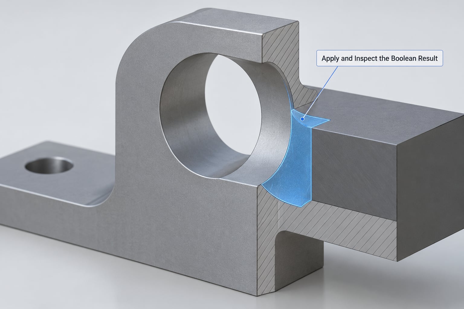
Run the operation, then look at the result before you do anything else. The commands are similar enough across packages to learn once:
| Software | Union | Difference | Intersection |
|---|---|---|---|
| Blender 4.x | Add Modifier > Boolean > Union | Add Modifier > Boolean > Difference | Add Modifier > Boolean > Intersection |
| Fusion 360 | Modify > Combine | Modify > Combine, flip tool body | Modify > Intersect |
| FreeCAD 1.0 | Part > Boolean > Union | Part > Boolean > Cut | Part > Boolean > Common |
| Tinkercad | Group both shapes | Place Hole with Shape over the cutter | Group both, then invert |
| OpenSCAD | union() { } | difference() { } | intersection() { } |
| Rhino 3D | Boolean > Union | Boolean > Difference | Boolean > Intersection |
In Blender, set the solver to Exact for anything you’ll print — Fast is quick but it approximates curves and gives you holes where cylinders meet boxes. Keep the modifier live while you work, and place it near the top of the stack so it reads finished geometry. A Boolean below a Solidify will feed a wall-thin shell into the operation and produce a silently wrong result rather than an error.
After applying, check four things. Orbit the model and confirm the new edge is a clean curve rather than a zigzag. Look for shading artifacts, which signal leftover n-gons or duplicate faces. Switch to wireframe or edge view and hunt for edges used by more than two faces. Finally, confirm the result is a single solid rather than a loose collection of shells — a polysurface prints as several disconnected pieces.
If the result is wrong, undo rather than patching. Move the cutter, give it more overlap, or switch solver, then run it again.
Repair, Simplify, and Export the Printable Part
Boolean results are rarely clean enough to slice without a pass of repair. Non-manifold edges — edges shared by three or more faces, or by none — are the ones slicers complain about, because they can’t decide which side is solid.
Work through it in this order:
- Run a mesh analysis. Import the STL into your slicer and look at the non-manifold edge report before touching anything else. It tells you how many faults and roughly where.
- Recalculate normals. Flipped normals read as inverted shells to many kernels. Most packages have an outside-facing normals command.
- Repair the errors. Blender’s 3D Print Toolbox analyses and corrects in one pass. Meshmixer and Netfabb do the same as standalone repair tools.
- Remove internal faces. Hidden cavity walls left inside a solid force infill where you don’t want it. In Blender, Mesh > Separate by Loose Parts and delete the internal shell, or use the limited dissolve with a small angle.
- Add fillets and chamfers last. Bevels applied before a Boolean get sliced apart by the new edge. Adding them afterwards gives you control over which edges round, and a 0.4 mm chamfer on a hole removes the stress riser the cut created.
- Export as 3MF where you can. 3MF carries units and colour; STL carries neither, so a scale mistake survives the export silently.
One more decision before export: multi-part or single solid. For a friction fit, keep the parts as separate bodies and let the slicer place them. Cutting the peg into the body and trusting the printer to self-align is how loose joints happen. Give a peg-hole pair 0.1 to 0.2 mm clearance for a snug FDM fit, 0.05 mm for resin.
Common Mistakes
Nearly every failed Boolean is one of seven things. Find the row that matches your symptom rather than retrying with different settings.
| Symptom | Likely cause | Fix |
|---|---|---|
| Union returns empty or unchanged | Bodies only touch on a coincident face | Overlap them by 0.1 mm or 1% of the larger width |
| Union fails on a closed pair of solids | Coincident or coplanar surfaces | Offset one body slightly, then union |
| Difference produces a union instead of a cut | Cutter fully encloses the target, so nothing is left outside it | Make the cutter pass through the wall |
| Difference returns nothing | Target sits entirely inside the cutter | Resize or reposition the cutter |
| Blender says “Failed to set value” | Geometry has open edges, flipped normals or self-intersections | Close the mesh, recalculate normals, use the Exact solver |
| Looks right, slices with holes | Leftover internal faces from the operation | Remove internal shells and re-check the manifold report |
| Result is correctly shaped but too fragile | Thin walls or near-tangent surfaces at the new edge | Thicken the wall, add a fillet, avoid tangent geometry |
Two habits prevent most of this. Overlap deliberately rather than exactly, and never trust a viewport — the manifold report is the truth.
Frequently Asked Questions
Which CAD software is best for boolean operations on 3D-printable parts?
For exact, parametric cuts, use a solid modeller such as Fusion 360, FreeCAD, Rhino 3D, Onshape or SolidWorks. Blender is fine too, provided you set the Boolean modifier to the Exact solver and convert imported meshes to solids first. Tinkercad suits simple holes and slots, while OpenSCAD suits code-driven parts you want to regenerate with different dimensions.
Should I do boolean operations in CAD or in my slicer?
Do them in CAD when you have the source files, because the result stays parametric and you can change the cutter later. Slice-side booleans act on meshes and are the practical option when you only have downloaded STLs and need a quick clearance cut. Slicer operations are approximate, so use them for fitting adjustments, not for defining final geometry.
Why does my boolean union keep failing?
Nine times out of ten the two solids only touch on a coincident face, so there is no shared volume for the kernel to work with. Nudge one body so it overlaps the other by about 0.1 mm, or roughly 1% of the larger body’s width. Also check for open edges and flipped normals on imported meshes, since either one stops the operation outright.
How do I fix non-manifold geometry after a boolean?
Import the STL into your slicer and read the non-manifold edge report to locate the faults. Recalculate normals so faces point outward, then run a repair pass in Blender’s 3D Print Toolbox, Meshmixer or Netfabb. Remove any internal shells left inside the solid, because those walls print as stray plastic or force unwanted infill.
Do I need a manifold, watertight model before 3D printing?
Yes, for FDM and resin printing a watertight, manifold mesh tells the slicer which side is solid. Non-manifold edges leave the slicer guessing, which shows up as missing layers, holes mid-print, or an over-inflated solid. Run the analysis on every export, especially after a Boolean, since that operation creates most of the faulty files in circulation.
Conclusion
Start with two closed solids that overlap by about 0.1 mm, then choose the operation that matches the geometry you want: union to join, difference to cut, intersection to keep only the overlap. Inspect the new topology before you do anything else, because a result that looks right in the viewport can still carry internal faces. Finally, export as 3MF and check the manifold report in your slicer. This workflow is still the fastest route to a clean part in 2026, and that last check is the one that separates a print that finishes from one that stops halfway up the build plate.