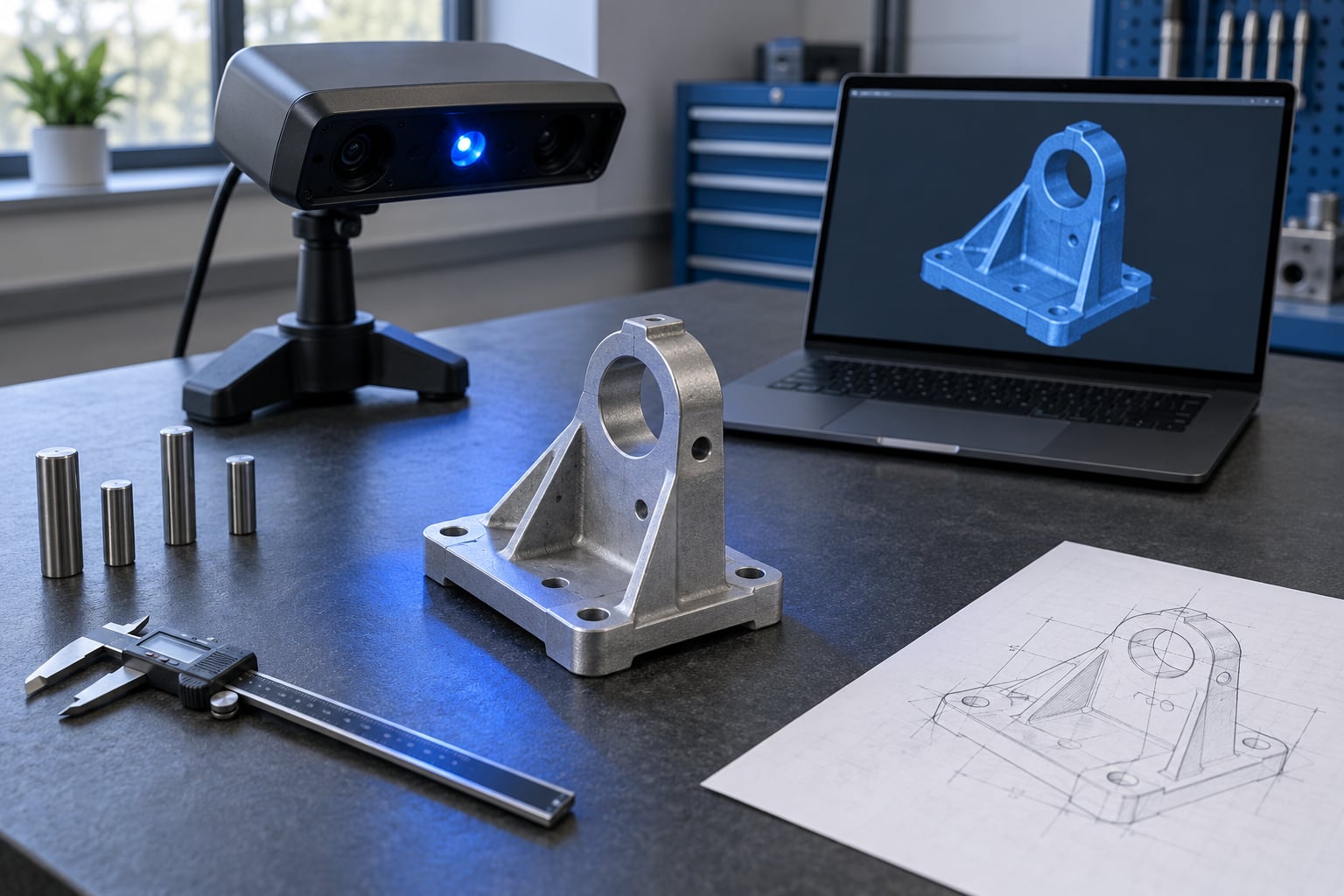
To measure a part for reverse engineering, start by naming three flat surfaces that never move relative to each other, treat them as your datum planes, and measure every critical feature from those planes. Hand tools such as calipers, micrometers and gauge pins handle the dimensions a scan would miss; a 3D scanner or coordinate measuring machine handles the shape. Budget a few hours for a simple bracket, longer for anything with a warped or worn surface.
The order matters more than the tools. Most inaccurate reverse engineering comes from measuring first and deciding what the numbers mean later, which is how you end up with a model that looks right and bolts nothing up.
Table of Contents
- What You Need
- Step-by-Step: How to Measure a Part for Reverse Engineering
- 1. Define the part and its reference planes
- 2. Choose the right measurement method
- 3. Measure the critical dimensions directly
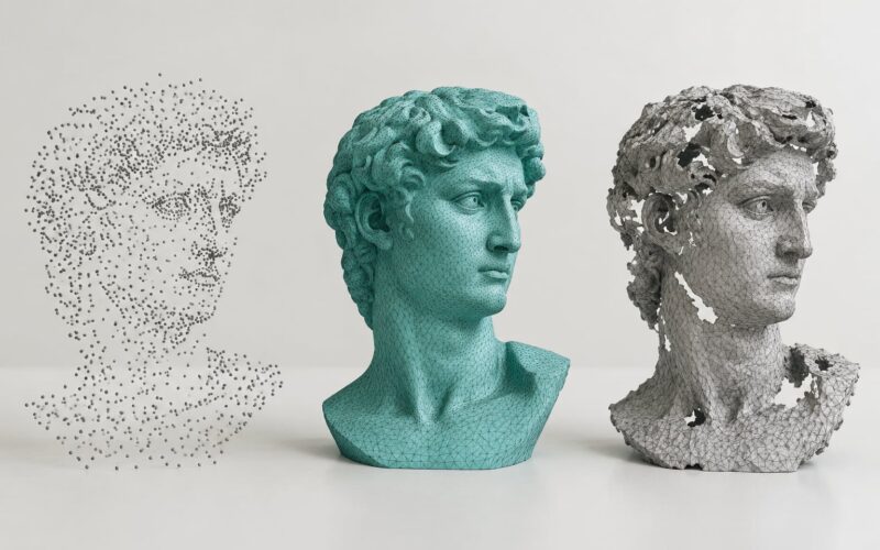
- 4. Capture the complete 3D shape
- 5. Align and clean the scan data
- 6. Validate the model in CAD
- 7. Document and verify the result
- Common Mistakes
- Frequently Asked Questions
- What is the best way to measure a part for reverse engineering?
- Do I need a 3D scanner to measure a part for reverse engineering?
- How accurate should reverse-engineering measurements be?
- How do I import a 3D scan into CAD software?
- What should I do when a 3D scanner cannot capture a surface?
- Conclusion
What You Need
Start with reference material. A working drawing, a parts manual, an assembly photo or even a photo of the part in place tells you what it does and which surfaces matter. Without that context you are copying geometry you may not need.
Hand tools cover most small parts:
- Digital or vernier calipers for outside and inside dimensions, step and slot widths. The zero-offset function lets you transfer a hole-to-hole spacing directly, which is the fastest way to lay out a bolt pattern.
- Outside micrometers for anything tight where caliper feel is not enough resolution.
- Gauge pins in a graded set for hole and shaft diameters. Press the closest pin that slides in, the next one up that will not, and your size is bracketed.
- Radius gauges for fillets and rounds, since a radius is often a standard value even when it does not look like one.
- Gauge blocks, angle blocks and a machinist square for building known heights, checking perpendicularity and stepping across a face that a caliper cannot span.
- Depth gauge or depth mic for blind holes and counterbores, plus thread gauges for identifying an internal thread.
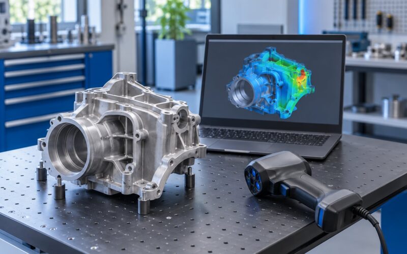
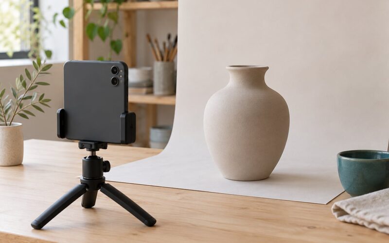
For shape, you have four realistic options. A structured light scanner projects a light pattern and reconstructs surfaces from the distortion, which suits matte plastic, painted metal and wood. A laser triangulation scanner uses a laser line and is the usual pick for shiny metal and machined parts. Photogrammetry uses many photographs and works on large parts you cannot put on a bench, but it needs good texture or coded markers. A coordinate measuring machine touches the part with a ruby probe and reports points numerically, which is slower but traceable and accurate.
A portable arm scanner sits between the scanner and the CMM: fast to move around a part, usually less repeatable at critical features than a CMM but far quicker than manual gauging.
Also worth having: a camera, a ruler or scale bar for scale reference, a notebook or spreadsheet, and CAD software that can accept mesh and point cloud data.
Step-by-Step: How to Measure a Part for Reverse Engineering
1. Define the part and its reference planes
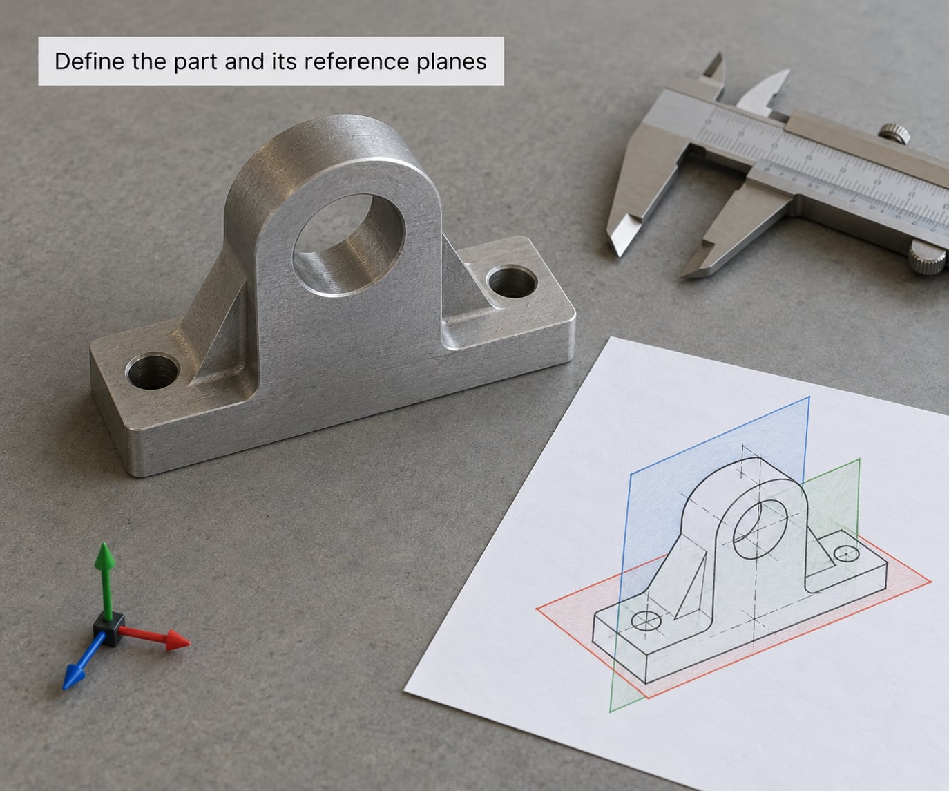
Look at the part before you touch it. Ask what it bolts to, what slides against it, and what wears first. Those answers tell you which surfaces are functional and which are casting flash you can ignore.
Pick three planes: usually the mounting face, one side face and the front face, which meet at a corner. Write down the scheme, for example “origin at the mounting face, zero on the left edge, Y from the front face.” Every later measurement gets quoted against those planes, so the model can be edited later without confusion.
Mark the planes on the part with a light scribe line or pencil if you can. Rest the part in the same orientation for every measurement and photograph it from three sides while you work.
2. Choose the right measurement method
Match the method to the tolerance you actually need and the geometry you are facing.
| Method | Typical accuracy | Works best on | Weak points |
|---|---|---|---|
| Caliper and gauge set | 0.01 to 0.03 mm on good tools | Flat parts, simple features, one-off work | Slow, no geometry, prone to hand error |
| Structured light scanner | 0.02 to 0.05 mm | Matte plastic, painted castings, organic shapes | Fails on chrome, black gloss, transparent surfaces |
| Laser triangulation scanner | 0.02 to 0.06 mm | Shiny and machined metal, small precision parts | Needs careful placement on every angle |
| Photogrammetry | 0.05 to 0.1 mm with coded markers | Large parts, boats, moulds, wreckage | Texture dependent, slow without markers |
| Coordinate measuring machine | 0.002 to 0.01 mm | Tolerance-critical fit checks and datum layouts | Highest setup cost, needs a stable environment |
Most shops scan the shape and hand-measure the dimensions that matter. Scanning gives you a surface you can trace, but it will not tell you whether a hole is 8 mm or 8.2 mm on its own, and it never sees the inside of a blind bore. Hand tools are still the source of truth for critical fits.
3. Measure the critical dimensions directly
Most people searching how to measure a part for reverse engineering want the same order of operations: overall size first, then features, then fits. Work outward from the datum corner.
For diameters, use the caliper jaws or micrometer across the round and confirm with a gauge pin where the fit matters. For hole positions, measure the distance from the datum edges to each hole centre rather than hole to hole, so every dimension chains back to the planes you defined.
Bolted holes are usually standard sizes, so identify the thread or clearance size first. Measure a few across a pattern and check whether the spacing is a round number like 20 mm or 0.500 inch. Experienced machinists call this finagling: record the raw reading, then look for the nominal even value the original designer would have specified.
Radii come from radius gauges. Angles come from an angle block or a sine bar, and most molded draft is a standard few degrees per side. For anything inside the part, use small bore gauges, telescoping gauges or a thread gauge, and swap micrometer heads if the internal diameter is tight.
Record each value with the tool you used and its resolution. A dimension read on a 0.01 mm caliper should never be written as if it were 0.001 mm accurate.
4. Capture the complete 3D shape
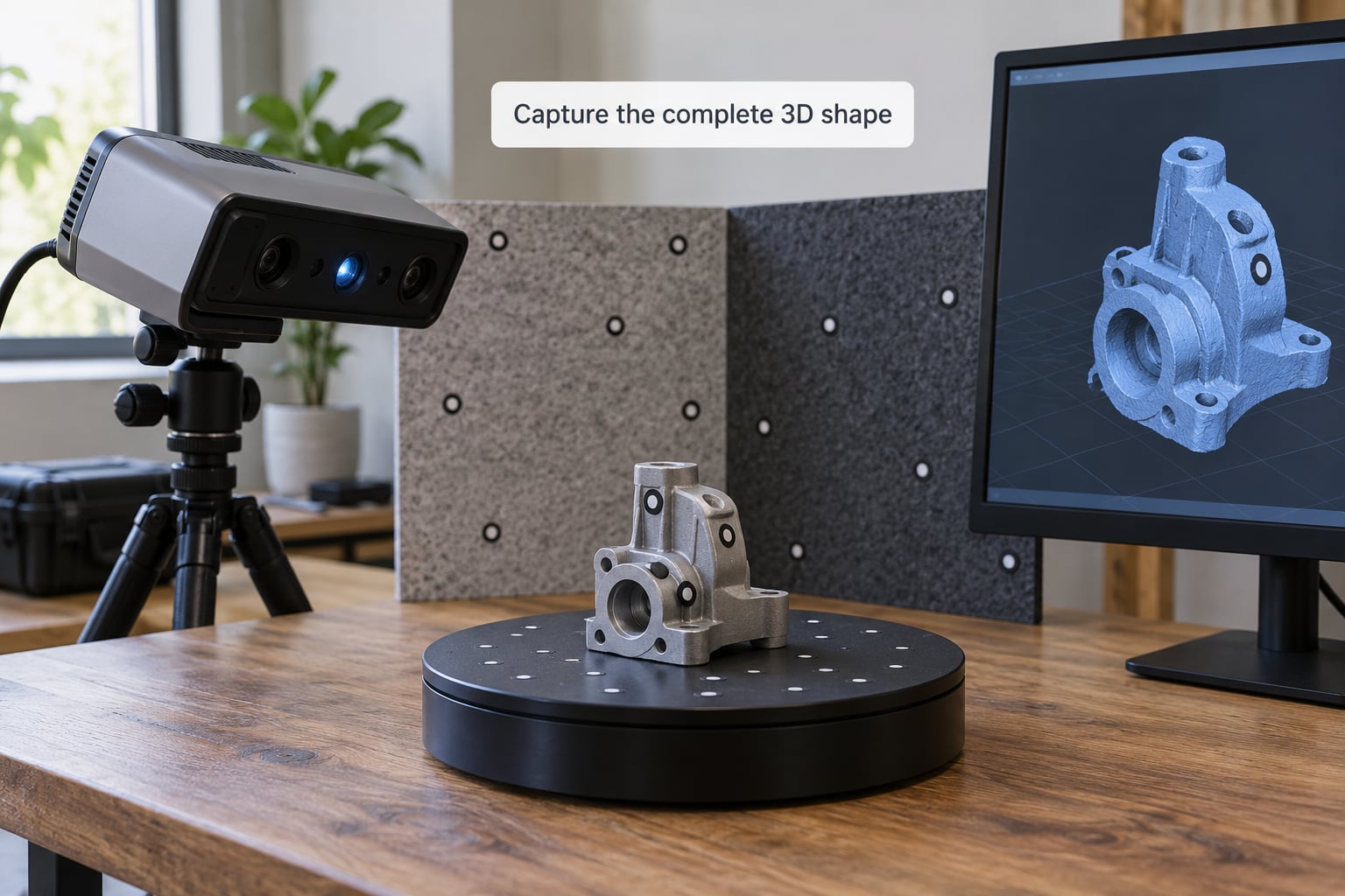
Set the part on a non-reflective surface. Black or white sprayed markers around the feature give the software something to track on smooth or dark surfaces, and a textured backdrop stops the camera from grabbing the room behind your part.
Cover the part in overlapping passes. Move the scanner or turntable roughly 30 to 45 degrees between shots and keep more than 30 percent overlap, since that is what the registration step needs to stitch the passes together cleanly. Take extra passes in cavities, because a deep hole seen from one angle is a missing surface.
Turn the part over. Capturing the top three passes and stopping is the classic mistake, and it leaves the underside reconstructed from guesswork.
5. Align and clean the scan data
Register the passes into one coordinate system first. Most software will do this automatically from the markers or from the shared surface texture, and you check the result by looking for doubled edges or a visible seam.
Merge the scans, then remove noise. Crop anything floating in space, delete stray islands, and fill small pinholes so downstream surfacing does not chase holes that never existed. Be careful not to fill a real hole.
Then check deviation. Compare the scanned surface against your datum planes and your hand measurements. If a dimension the scan was supposed to capture disagrees with the caliper reading by more than your scanner’s stated accuracy, the scan is wrong, not the caliper. Look for scale loss first, since a unit or calibration error scales the entire model.
Keep holes, threads and fillets as separate features rather than smoothing them into the surrounding surface. Threads are almost never scanned correctly; use a thread gauge and model them as a standard callout.
6. Validate the model in CAD
Import the mesh or point cloud into your modeling software, scale it against a known dimension such as the overall length you measured by hand, and align it to your datum planes.
There are three ways to get geometry out of it. You can trace the section curves and build a solid parametrically, which gives the cleanest result and a model you can edit later. You can auto-surface the point cloud into NURBS bodies, which is fast on organic or damaged shapes but produces a shell that is hard to change. The hybrid route is the practical compromise: model standard features parametrically and surface only the freeform areas.
Whichever route you take, close the model and check it. Compare the CAD dimensions against your hand measurements one by one, then use the deviation or interference tools in the software to see where the model sits inside or outside the scan.
7. Document and verify the result
Write a short measurement record next to the model: units, datum scheme, each hand-measured dimension with the tool used, the scanner settings, the scan date, and any assumptions you made about worn surfaces.
Where a surface is damaged or heat-warped, say so in the record and model the feature you believe was original rather than the shape you found. That is design intent recovery, and it is the difference between reproducing a defect and reproducing a part.
Finish with a verification pass. Print or machine a test piece at reduced scale, fit it to the original, and check alignment at the bolt holes and any sliding surfaces before committing to full size.
Common Mistakes
- Measuring with no datum. Fix: choose the three planes before the first reading and quote every dimension from them. Almost every bad model traces back to one wandering reference.
- Tool resolution finer than the tool. A caliper with 0.01 mm resolution is not accurate to 0.01 mm. Fix: record the tool and its stated accuracy, and reserve micrometers or gauge blocks for the few dimensions that must be tight.
- Scanning shiny or transparent surfaces. Chrome, bare aluminium and clear plastic give black holes in the mesh. Fix: spray a matte developer coat, or add high-contrast markers and scan the edges instead.
- Losing scale. A scan without a known length reference or calibration target can be off by a constant factor. Fix: scale against a dimension you measured by hand before you do anything else in CAD.
- Trusting the scan without checking it. Fix: hold the model against the original or measure both with the same caliper. Watch for reversed or mirrored holes, which registration does not catch.
- Recording odd numbers as final. A hole that measures 7.98 mm is almost certainly an 8 mm hole. Fix: keep the raw value, model the nominal, and note the deviation.
- Ignoring worn surfaces and heat distortion. Fix: measure several undamaged locations on the same feature, and use the readings that agree with each other as the true size.
- Measuring a warm part. Metal expands, and a part straight out of a machine will read high. Fix: let it reach room temperature and keep it off the sunlit bench.
Frequently Asked Questions
What is the best way to measure a part for reverse engineering?
Start with three stable reference planes and measure every critical dimension from them, then capture the freeform shape with a 3D scanner. Hand tools stay the source of truth for hole sizes, fits and anything inside the part, because a scan rarely resolves those features. Photograph the part and record each reading with the tool used before moving anything.
Do I need a 3D scanner to measure a part for reverse engineering?
No. Machinists have reproduced complex parts for decades with calipers, gauge pins, gauge blocks, radius gauges and angle blocks alone. That route is slower and depends on careful datum work, but it is enough for flat plate parts, brackets, housings and adapters. A scanner pays off when the shape is curved, organic or when you need a full surface rather than a set of dimensions.
How accurate should reverse-engineering measurements be?
Match the accuracy to what the part does. A cosmetic cover needs roughly a tenth of a millimeter, a sliding fit needs closer, and a press or bearing fit needs the tightest control you can get. Measure several times and from different positions, and if the readings disagree by more than the tool resolution, the surface or your technique is the problem, not the part.
How do I import a 3D scan into CAD software?
Export the scan as a point cloud or triangle mesh, then use the import command in your CAD package to bring it in as a reference body. Scale it against a dimension you measured by hand, then align it to your datum planes. Fit section curves on the mesh or surface the cloud directly, and keep the scan object on a hidden layer so it never merges with your solid model.
What should I do when a 3D scanner cannot capture a surface?
Change the surface before you change the plan. A thin matte spray developer coat works on shiny metal, and high-contrast markers help on dark or featureless plastic. For deep cavities, scan from several angles with the part tilted. Clear or transparent material usually has to be re-made or measured entirely by hand, since light scanners cannot see through it at all.
Conclusion
The order of operations is the whole trick. Identify the functional surfaces and lock down three datum planes, measure the critical dimensions by hand while the part is still in front of you, scan for the freeform shape, clean and align the data, then trace the model and check it dimension by dimension against your original readings.
Start today by deciding which surfaces carry the load, marking three reference planes on the part with a pencil, and writing down the overall dimensions with the tool you used for each one. Everything after that gets easier, because the model has somewhere to hang from.