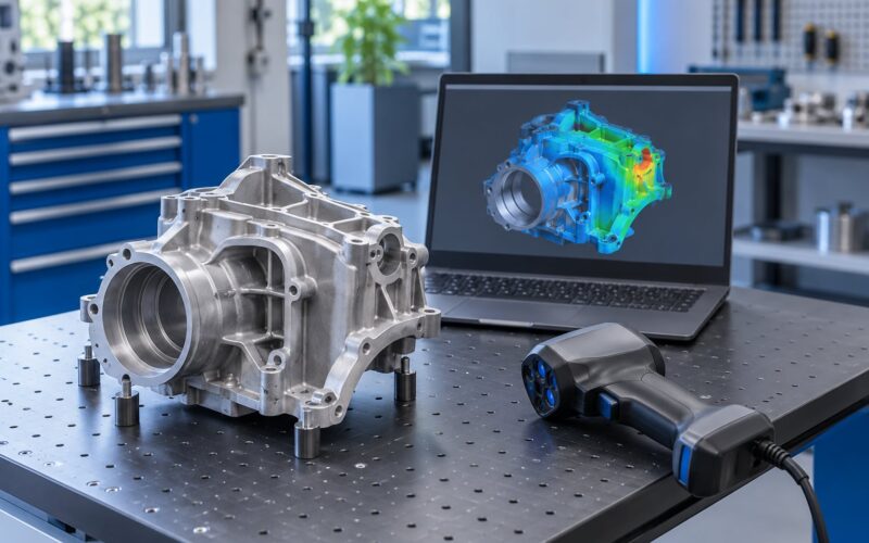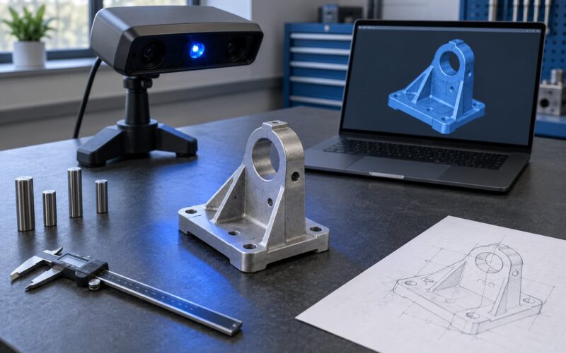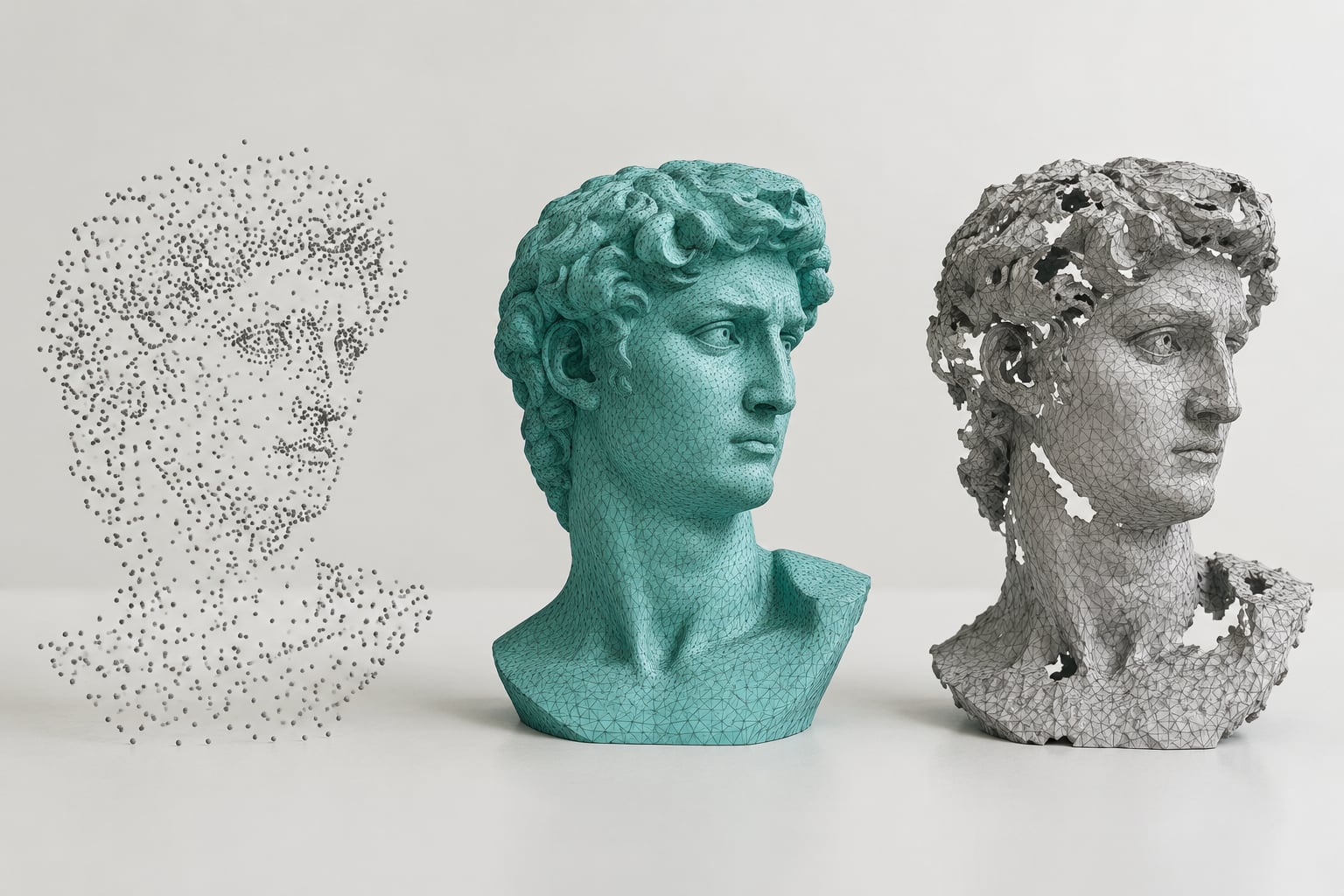
Point cloud to mesh conversion is the process of turning a loose cloud of measured coordinates into a connected surface made of vertices, edges and triangular faces. Scanners record millions of independent points, and software has to infer the surface that connects them before a printer, game engine or CAD package can use the data at all.
The short version of the workflow: clean the cloud, estimate normals, run a surface reconstruction algorithm, trim the low-confidence parts, repair holes, then export a format your downstream tool understands. Most bad meshes trace back to skipping one of those steps rather than to a bad algorithm choice.
Table of Contents
- What Is Point Cloud to Mesh Conversion?
- How Does Point Cloud Reconstruction Work?
- Neighbourhood search
- Normal estimation
- Surface fitting
- Triangulation and cleanup
- What Are the Main Point Cloud to Mesh Methods?
- Poisson surface reconstruction
- Ball pivoting algorithm
- Alpha shapes
- Delaunay triangulation
- Volumetric and signed-distance approaches
- How Do You Choose the Right Conversion Settings?
- Octree depth
- Ball radius and sample count
- Point density and subsampling
- Normal direction and consistency
- Hole filling and decimation
- How Do You Clean and Prepare a Point Cloud Before Conversion?
- What Software Can Convert Point Clouds to Meshes?
- CloudCompare
- MeshLab
- Blender
- FreeCAD
- Scripted routes
- Commercial options
- What File Formats Can You Export?
- How Can You Tell Whether the Converted Mesh Is Good?
- Frequently Asked Questions
- What is the difference between a point cloud and a mesh?
- Can every point cloud be converted into a watertight mesh?
- Which reconstruction method is best for a scanned object?
- Why does my converted mesh contain holes or noisy surfaces?
- Should I smooth the point cloud before converting it to a mesh?
- What mesh format should I use for 3D printing or CAD work?
- Conclusion
What Is Point Cloud to Mesh Conversion?
A point cloud is an unordered set of coordinates, usually X, Y and Z, sometimes with colour or intensity attached. There is no surface in that data, only samples of where a surface probably is. A mesh is the opposite: an ordered structure where vertices are joined by edges and edges bound faces, so the software knows which side of the surface it is looking at.
You can think of a point cloud as a handful of seeds scattered over a shape and a mesh as the tree grown from them. The reconstruction algorithm decides how far the branches reach and how they join, which is why the same cloud can produce several very different meshes.
| Attribute | Point cloud | Mesh |
|---|---|---|
| Structure | Unordered points with coordinates | Vertices, edges and faces |
| Surface continuity | None, gaps between samples | Continuous closed or open surface |
| Typical file size | Very large, raw scans often tens of gigabytes | Much smaller after decimation |
| Measurement accuracy | Best, nothing is interpolated | Good near samples, interpolated in between |
| Editability | Hard to edit by hand | Vertices and faces can be moved directly |
| Volume and area maths | Approximate only | Exact once the mesh is closed |
| Typical uses | Surveying, as-built capture, heritage records, metrology | 3D printing, rendering, simulation, CAD and BIM |
| Common formats | E57, LAS, LAZ, PLY, XYZ | STL, OBJ, PLY, glTF, FBX |
Meshes are required for almost everything downstream. A slicer wants a watertight triangle soup in STL, a game engine wants an optimised mesh it can draw at 60 frames per second, a solver wants manifold geometry, and a BIM authoring tool wants structured geometry it can parameterise. Point clouds alone support none of that.
How Does Point Cloud Reconstruction Work?
Reconstruction is really a sequence of guesses. The software works out what the surface looks like locally, stitches those local views together, then throws away the parts it is not confident about.
Neighbourhood search
Every point needs to know its neighbours. Algorithms typically use a K-nearest-neighbour search, commonly K between 10 and 20 in practice, to gather the local points that describe the surface around it. Too small a neighbourhood and detail is lost; too large and flat surfaces start to bow.
Normal estimation
Each point gets a vector perpendicular to the local surface, which is how the algorithm knows which way is out. Normals have to point the same way across the whole object, otherwise the mesh comes out inside-out. Consistency matters more than precision here, since a consistently flipped normal is easy to fix afterwards and a randomly flipped one is not.
Surface fitting
With normals in hand, the software fits a surface to the point set. Some methods build an implicit function, a scalar field where each point in space has a value, then extract the zero level set. Others build triangles directly between neighbouring points and accept what stays connected.
Triangulation and cleanup
The fitted surface becomes triangles, and confidence values come along with them. Low-confidence regions, usually far from any real sample, get trimmed away. What is left is a mesh that still needs hole filling, normal checks and decimation before it is useful.
That last stage is where most tutorials end and where most projects actually fail. A mesh straight out of reconstruction is a starting point, not a deliverable.
What Are the Main Point Cloud to Mesh Methods?
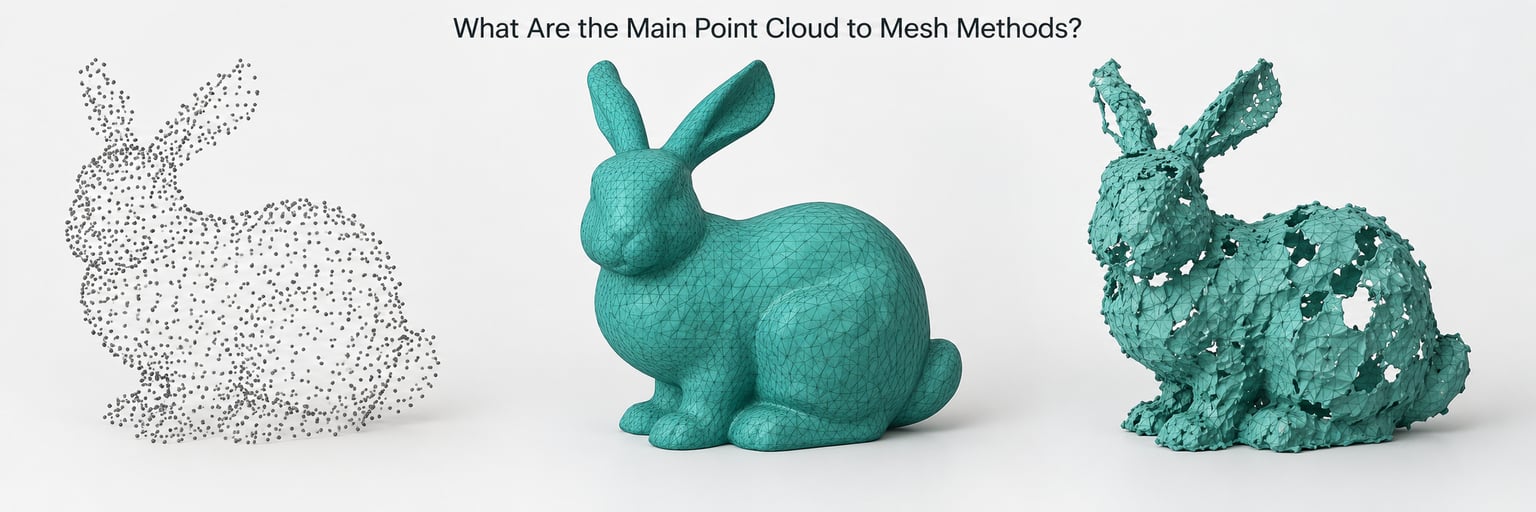
Five approaches cover almost every real-world case. They differ mainly in whether they build the surface implicitly first or connect the points directly, and that choice decides how they behave around holes, sharp edges and noisy data.
Poisson surface reconstruction
Poisson fits an implicit function to the samples and extracts its zero level set, producing a closed surface. It is fast on large clouds and handles noisy data well, which is why it is the default in most free workflows. The failure mode is smoothing: sharp corners get rounded off and unsampled regions get filled with speculative geometry. It also needs consistent normals, which is why you will see the phrase “cloud must have normals” in CloudCompare troubleshooting threads.
Ball pivoting algorithm
Ball pivoting rolls a virtual ball of a chosen radius across the point set, and wherever it touches three or more points at the right spacing it stamps out a triangle. It produces a mesh that follows the samples more literally than Poisson, so edges and engraved detail survive. It fails when point spacing is uneven relative to the ball radius, and it does not close large gaps by itself. This is the method community members tend to recommend for large, sheet-like datasets such as architectural scans.
Alpha shapes
Alpha shapes treat the points as a weighted set and build a shape whose boundary depends on a single alpha value. Small alpha keeps the surface tight and detail-rich; large alpha pushes it outward and smooth. It is fast and intuitive to tune, but it is sensitive to scale, so you have to set alpha in the same units as your scan.
Delaunay triangulation
Delaunay builds the tetrahedralisation of the point set, giving a natural way to connect neighbours without crossing triangles. It is the geometric foundation under ball pivoting and several volumetric approaches, and in Python it is reachable through scipy. On its own it produces a tetrahedral blob rather than a surface, so it is rarely the final answer.
Volumetric and signed-distance approaches
These treat the cloud as occupancy data and extract isosurfaces, marching cubes being the classic example. If your data already has volume or distance attributes, such as LiDAR intensity or a signed distance field, the output is very clean. Raw scan coordinates need an extra step to become occupancy data first.
| Method | Best for | Strength | Where it fails |
|---|---|---|---|
| Poisson | Noisy clouds, quick watertight results | Fast, tolerant of gaps | Rounds sharp edges, invents geometry in holes |
| Ball pivoting | Architectural scans, fine detail | Follows samples closely | Sensitive to ball radius, needs fairly even spacing |
| Alpha shapes | Small objects, fast previews | One intuitive parameter | Scale-dependent, weak on large scenes |
| Marching cubes | Voxel or occupancy data | Fast, watertight by construction | Needs volumetric input, blocky at low resolution |
| Delaunay based | Custom and scripted pipelines | Full control, no black box | You build the surface logic yourself |
How Do You Choose the Right Conversion Settings?
Almost every bad reconstruction traces back to a setting that was left at the default. Here are the controls that actually move the result.
Octree depth
This is Poisson’s main resolution control. Depth 8 to 12 is the range people report using most often, with higher values capturing finer detail at a steeply rising memory cost. Push it too high on a large cloud and the process runs out of RAM.
Ball radius and sample count
For ball pivoting, the radius needs to sit above your typical point spacing and below the smallest feature you care about. A useful sanity check is to measure the mean distance between nearest neighbours and start the radius a little above that. The sample count controls how many points must support each triangle.
Point density and subsampling
Very dense clouds slow everything down and can smooth away the detail you wanted. Subsampling to somewhere between 500k and 1M points before meshing is common practice, since beyond that the extra points add compute time rather than shape accuracy.
Normal direction and consistency
Estimate normals with a K-nearest-neighbour radius or count, orient them consistently, then visually inspect a few regions. Reversing global orientation is a one-click fix; scattered inconsistent normals are not.
Hole filling and decimation
Set a maximum hole size to fill so you close real occlusions without sealing deliberate openings such as a handle grip. Decimate only after the mesh is clean, and check the volume before and after, since aggressive decimation quietly shrinks curved surfaces.
How Do You Clean and Prepare a Point Cloud Before Conversion?
Cleaning is unglamorous and it saves more time than any algorithm choice. Each step below prevents a specific defect you would otherwise chase later.
Check units and scale first. A cloud in millimetres fed into a tool expecting metres produces a model a thousand times too large, and the error only shows up when the mesh lands somewhere absurd in your scene.
Register the scans. Align overlapping scans with ICP or manual tie points before meshing. Misregistered scans create doubled walls and layered floors, and no reconstruction algorithm can untangle that.
Remove outliers. Statistical and radius outlier removal filters delete the ghost points caused by reflections, dust or people walking through. Run this before subsampling so the filter sees real density rather than a decimated sample.
Subsample evenly. A voxel or spatial grid subsample gives more even spacing than random sampling, which directly helps ball pivoting and alpha shapes.
Compute normals and check orientation. Do this on the subsampled cloud, since it is far faster and the normals are what the reconstruction actually consumes.
Crop the region you need. Meshing a whole building when you need one facade wastes time and drags in noise from everything else in the scene.
What Software Can Convert Point Clouds to Meshes?
The free tools cover this workflow properly. Commercial packages add automatic registration, better colour handling and CAD output, which matters once the job is billable.
CloudCompare
The most commonly recommended free route, especially with the PoissonRecon plugin. It handles import, cleaning, subsampling, normals, Poisson reconstruction and density-based trimming in one place, and it reads E57 and LAS directly. It is the tool to start with if you have never meshed a scan before.
MeshLab
The stronger choice for mesh-side work: Ball Pivoting, Poisson surface reconstruction, filters for holes and non-manifold edges, and Poisson disk decimation. It is also the usual bridge to retopology when the mesh needs to be rebuilt by hand.
Blender
Useful once you need topology for game assets, since retopology and decimation happen naturally alongside shading and export. Blender 4.0 and later can bring points in through the Points to Curves node for a rough surface you can remesh.
Mesh a lot of scans in Blender and you will find the point import path has improved, but for pure point cloud conditioning MeshLab and CloudCompare stay ahead. Blender’s real strengths are animation, materials and export pipelines.
FreeCAD
The pick when the end goal is a parametric CAD solid. You convert to a mesh, clean it, mesh to shape, and take a shape from there.
Scripted routes
Open3D and trimesh in Python are the answer for batch work, where hundreds of scans follow the same pipeline. The library calls are simple; the parameter tuning is where the time goes, and it is the same tuning described above.
Commercial options
Autodesk ReCap and ReCap Pro, Geomagic Design X, FARO RealityCapture and Prevu3D all handle registration and reconstruction together, and they will convert vendor scan formats such as RCP and RCS that free tools often cannot open. ReCap is the common bridge that turns RCP or RCS into E57 for CloudCompare or MeshLab.
What File Formats Can You Export?
Export picks what survives the trip to your next tool. Format matters most when colour, scale or topology has to stay intact.
| Format | Geometry | Colour and texture | Best used for |
|---|---|---|---|
| STL | Triangles only, no shared vertices | None | 3D printing and slicers |
| OBJ | Vertices, normals, UVs | Vertex colour and texture maps | General modelling and rendering |
| PLY | Vertices and faces, extensible header | Vertex colour, custom properties | Carrying scans and meshes through a pipeline |
| glTF | Optimised indexed meshes | PBR materials and textures | Real-time viewers and game engines |
| FBX | Mesh plus rig and animation data | Materials and texture links | Game engines and DCC interchange |
STL is the safe pick for printing, but it carries no units and no colour, so confirm the scale in your slicer before sending it. OBJ is the most forgiving choice when colour matters. PLY keeps the scan attributes intact, which makes it handy as an intermediate. For web and real-time work, glTF keeps the polygon count and texture layout intact in a much smaller file.
One recurring complaint is colour that does not line up with the geometry after conversion. Vertex colours survive if you export to OBJ or PLY and stay out of STL entirely. Texture maps need a separate UV unwrap step, since reconstruction does not produce one.
How Can You Tell Whether the Converted Mesh Is Good?
Run through this list before you export. Every item is visible in MeshLab, Blender or CloudCompare in under a minute once you know where to look.
Compare against the original scan. Toggle between the cloud and the mesh and look for features that vanished, usually the first sign of over-smoothing.
Check the bounding box and scale. A model that should be 300 mm across should measure 300 mm in the scene, not 0.3 mm or 300 m.
Look for holes and non-manifold edges. The boundary and non-manifold edge filters will list them. For printing, every boundary edge is a leak.
Inspect normals. Shade the mesh smooth or use a two-sided lighting setup. Patchy black blotches mean flipped or inconsistent normals.
Look for self-intersection. Turn on backface culling. Faces that disappear from certain angles are intersecting or inverted.
Count polygons against your budget. Raw scans can produce meshes in the tens of millions of triangles, and downstream tools choke on that. Decimate to what the tool can handle.
Measure volume if the shape is solid. A printed part and a CAD solid should agree closely. A mismatch means remaining holes or overlapping geometry.
Confirm alignment. Overlay the mesh on the cloud and check that features line up in every axis, not just the obvious one.
Frequently Asked Questions
What is the difference between a point cloud and a mesh?
A point cloud is an unordered set of measured 3D coordinates with no defined surface between the samples. A mesh connects vertices with edges and faces into continuous geometry, so it has a defined inside and outside. Point clouds keep the raw measurement, while meshes support printing, rendering, simulation and CAD work. Meshes interpolate between samples, which smooths detail but adds the structure those tools need.
Can every point cloud be converted into a watertight mesh?
Yes, a closed mesh can be produced from almost any cloud, but watertight does not mean accurate. Algorithms such as Poisson will happily fill regions the scanner never reached with invented geometry. Where a surface is genuinely unobserved, you are guessing. For printing, fill holes under a sensible size limit and mark anything larger so a human decides whether to model it by hand.
Which reconstruction method is best for a scanned object?
Poisson is the safest default because it is fast, tolerant of noise and always returns a closed surface. Use ball pivoting when sharp edges and fine detail matter more than a guaranteed solid, since it follows the samples more literally. Alpha shapes suit small objects with a single tuning parameter. Volumetric methods need occupancy data rather than raw coordinates.
Why does my converted mesh contain holes or noisy surfaces?
Holes usually mean no samples reached that area, so the algorithm had nothing to fit, or the gap exceeded your filling limit. Lumpy surfaces point to leftover outliers, uneven point spacing, or normals that were never made consistent. Misregistered scans create doubled and layered surfaces that no filter fixes. Clean the cloud, register it properly and check normals before rerunning the reconstruction.
Should I smooth the point cloud before converting it to a mesh?
Only lightly, and only to knock off measurement noise rather than to tidy the shape. Heavy smoothing before meshing deletes fine detail, and you will wish you had it back when it comes to retopology. Remove statistical outliers and subsample instead, then let the reconstruction handle light noise. If the result is still lumpy, the problem is more often normals or spacing than a missing smoothing pass.
What mesh format should I use for 3D printing or CAD work?
STL is the standard for printing, since every slicer reads it, but it stores only triangles with no units or colour, so confirm the scale in your slicer first. For CAD work, export through your CAD tool to a solid format such as STEP, using the mesh only as the reference shape. Use OBJ or PLY when you need vertex colour, and glTF for real-time viewers.
Conclusion
Point cloud to mesh conversion works because reconstruction algorithms infer a continuous surface between measured samples, and the result is only as good as the cleanup that came before it. Start by inspecting and cleaning the cloud, register it, remove outliers, subsample and get the normals consistent. Then pick Poisson for speed and closure or ball pivoting for detail, trim the low-confidence regions and repair the holes before exporting.
Check the finished mesh against the original scan for holes, flipped normals and scale before it goes anywhere near a slicer or an engine.