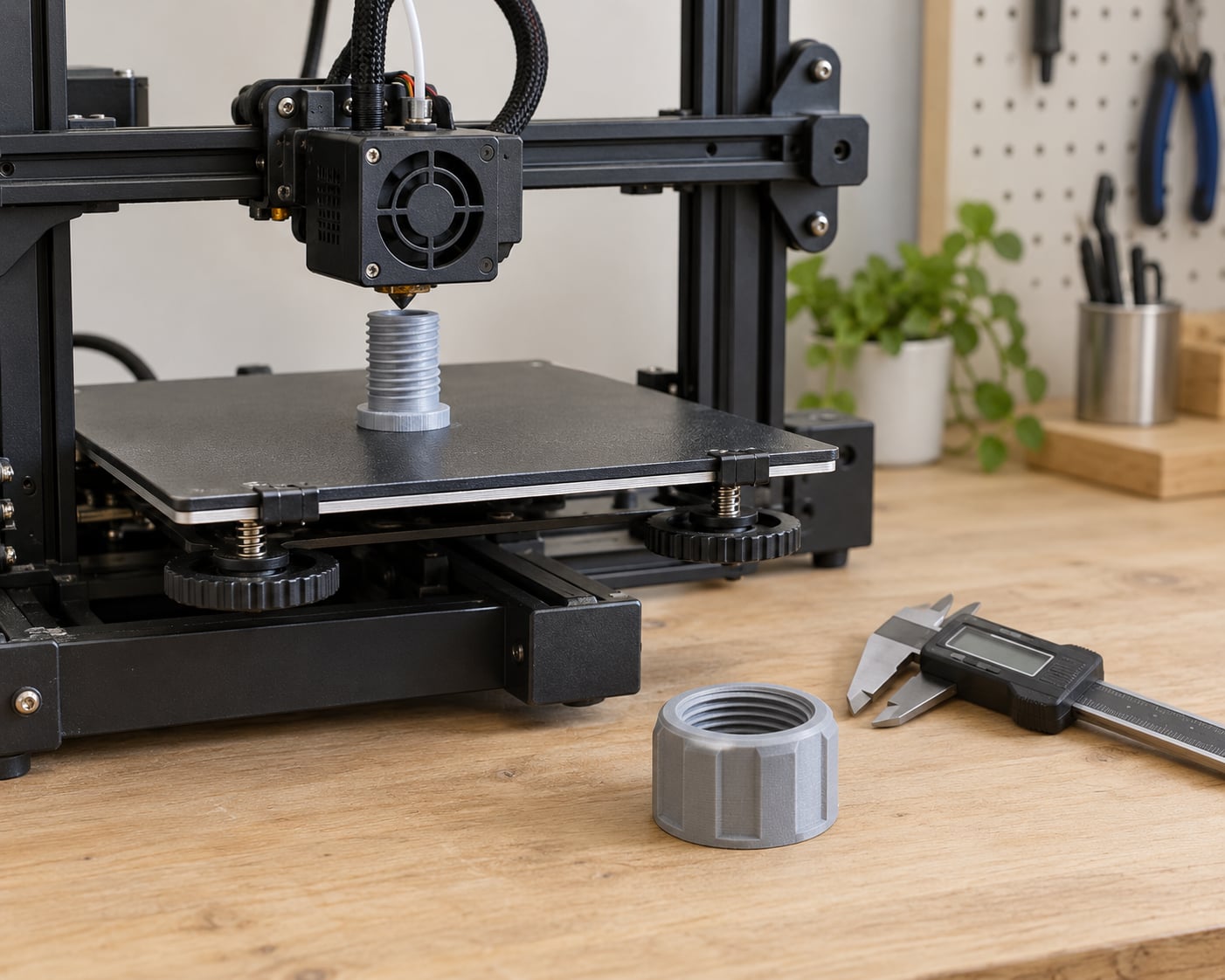
A 3D printer can print threads that screw together. The helix gets built as a stack of partial layers, so it comes out slightly fat and slightly wavy, and the mating part still mates fine once you add clearance and test a short coupon first. The hard part isn’t printing the thread. It’s choosing the pitch and the gap.
If you are working out how to print threads that screw together and the parts keep binding, cross-threading or spinning loose, the answer is almost never a better printer. It is a coarse-enough thread, real clearance between the two halves, and a ten-minute test coupon before you commit four hours of filament.
Budget roughly an hour for the CAD work, then ten minutes per test print. Once you have one successful coupon, the same numbers work on every part you model afterwards.
Table of Contents
- What You Need
- Essential: a CAD program that can make a real thread
- Essential: an FDM printer that holds its XY dimensions
- Essential: a slicer you understand well enough to adjust
- Essential: digital calipers and a material for repeated mechanical use
- Helpful but optional: the testing hardware
- Step-by-Step
- Choose a Thread Standard and Measure the Nominal Size
- Model the Male and Female Threads with Clearance
- Orient the Part for Strong, Clean Threads
- Set the Slicer for Functional Parts
- Test the Fit and Adjust in Controlled Increments
- Print and Inspect the Final Assembly
- Common Mistakes
- Frequently Asked Questions
- Can a normal FDM printer make threads that actually screw together?
- Do I need CAD software with a dedicated thread generator?
- Should 3D-printed screw threads be printed vertically or horizontally?
- What clearance should I use for my first FDM thread test?
- Why does my threaded part fit at the opening but bind deeper inside?
- Start With a Calibrated Test Pair
What You Need
Four things are genuinely required. The rest make testing faster, not the threads better.
Essential: a CAD program that can make a real thread
The program has to produce actual helical geometry, not a spiral drawn on a surface. Autodesk Fusion 360’s Thread tool does this and has a free personal-use license, so it is the usual starting point. FreeCAD’s Part Design thread primitive and OpenSCAD with the threads library both work too, and the OpenSCAD route is a good second opinion when you want to check a fit in code rather than by dragging a dialog.
Essential: an FDM printer that holds its XY dimensions
You do not need a resin printer or a corexy machine. You need a printer whose external walls repeat the same width on every layer and every print, and whose first layer does not squash into an elephant foot. Threads expose every dimensional wobble your other parts hide, because the fit is measured in tenths of a millimetre and the flank has to be a smooth ramp rather than a staircase.
Essential: a slicer you understand well enough to adjust
PrusaSlicer, Cura or Bambu Studio all expose layer height, line width, wall loops, seam placement and flow multiplier. That is every control that matters for a threaded part. If you cannot find those settings in your slicer, you cannot print a functional thread with it.
Essential: digital calipers and a material for repeated mechanical use
Calipers are the non-negotiable item. Guessing at clearance is guessing at your printer, and you need to measure the coupon to know what your machine is actually doing. PLA is the easiest material to start with because it holds a hole to size and does not warp, PETG is tougher but fussier, and ABS or ASA need an enclosure or they will print a hole that is out of round by the time you thread it.
Helpful but optional: the testing hardware
A tap and die set, a soldering iron and a few brass heat-set inserts let you compare the three different approaches against the same coupon. They are worth it if you build enclosures or camera gear regularly, and skippable if this is a one-off part.
Step-by-Step
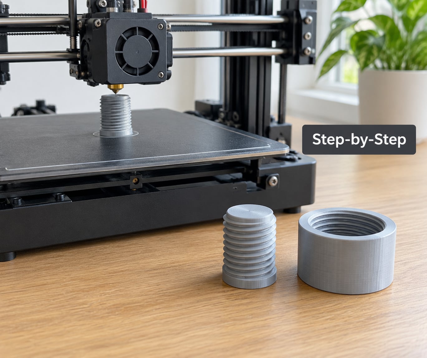
Six stages, in order. Skipping ahead to the print is how most people end up with a scrap part and a coupon they should have run first.
Choose a Thread Standard and Measure the Nominal Size
Start from a recognised standard, never a freehand helix. ISO metric is the easiest to source and the easiest to buy hardware for, and every metric thread uses the same 60 degree profile, so one set of numbers transfers between M3 and M8. If you need imperial, use UNC or UNF from a table rather than guessing, because the profile angle is the same 60 degrees but the pitch numbers are different.
Four numbers define the thread you are modelling: the major diameter, which is the outside diameter of the male thread; the pitch, which is how far the thread advances per turn; the profile angle; and the minor diameter, the inside diameter of a female thread. Engagement length is how far the two parts overlap, and thread count is simply engagement length divided by pitch. Four to six engaged threads is a reasonable target for a printed joint.
The choice that matters most is coarse versus fine pitch. A coarse thread has thick teeth, and thick teeth survive a 0.4mm extrusion width. A fine thread has a thin crest: on an M6 x 1.0 the material at the crest is roughly 0.37mm, which is thinner than the line your printer lays down, so the helix comes out rounded and slightly fat on both the crest and the root. Go up in pitch or up in diameter instead. M6 x 1.75 prints well, and so does most coarse bottle-thread geometry.
Nominal size tells you what the thread is called. It does not tell you the two printed parts will mate. A tolerance class from a manufacturing table assumes a machine tool holding dimensions to hundredths of a millimetre, and no FDM printer does that.
Model the Male and Female Threads with Clearance
Model the external thread the normal way, then give the internal opening more room. In Fusion 360, place the thread tool on the circular edge and use the ISO Metric profile. The important checkbox is Model Thread: leave it clear and you get a cosmetic line that will not export, which is the single most common way beginners end up with an STL that has no thread at all.
Then select the face of the internal hole and offset it inward by about 0.2mm per face. That is your radial clearance, and it is the number that makes the joint work. Diametral clearance is the same gap measured across the whole part, so 0.2mm per face means 0.4mm of diametral clearance, and the two descriptions are easy to mix up when you are comparing figures from different sources.
Filleting the thread edges by about 0.3mm is the second half of the fix. Sharp thread corners catch the opposing flank on the first turn and produce the binding that gets blamed on tolerance when it is really geometry. Breaking those corners lets the parts slide past each other during the first half turn.
Modelling a true internal helix is where FDM frustrates people. A properly cut internal thread means sweeping the profile, trimming the sweep to the hole length and cleaning up the ends, and a failed boolean leaves a broken body. The practical first pass is to build the male thread as a separate solid, enlarge it by the clearance amount, and cut it out of the female part with a boolean. Library nut STLs work the same way: boolean-cut one into the other part, then scale the result until the fit is right.
Starting clearance per face, which is what you type into the offset tool:
- M4 x 0.7, 0.20 to 0.25mm
- M5 x 0.75, 0.20 to 0.25mm
- M6 x 1.0 and M6 x 1.75, 0.25 to 0.30mm
- M8 x 1.25 and M8 x 1.75, 0.30 to 0.35mm
Add 0.05mm at both ends of those ranges if your printer drifts on long prints, if the material is ABS or ASA, or if the part will be used warm. M3 x 0.5 is not worth attempting as a printed-in thread on a typical machine, because the crest thickness is well under 0.2mm. Use an insert or a real screw at that size.
If you would rather not model a helix at all, these are the two alternatives and their starting dimensions. Heat-set insert hole diameter: M3 around 4.0 to 4.2mm, M4 around 5.0 to 5.2mm, M5 around 6.0 to 6.3mm, M6 around 7.8 to 8.0mm, M8 around 9.9 to 10.1mm. Always check the sheet for the specific insert, because length changes the figure, and print 0.1 to 0.2mm oversize if you are on the boundary.
Predrill before hand-tapping: M3 at 2.6 to 2.8mm, M4 at 3.4mm, M5 at 4.2 to 4.3mm, M6 at 5.0 to 5.2mm, M8 at 6.8 to 7.0mm. Printed holes are less forgiving than metal, so sit at the top of the tap drill range rather than the bottom. If you only want a screw to bite into plastic and never to come out, an M3 into a 3.2 to 3.4mm clearance hole works with a thread-forming screw instead of a tap.
Orient the Part for Strong, Clean Threads
Print the thread axis vertical for most parts. Every layer then has the same thread profile in plan view, so the outer perimeter traces a complete, continuous flank instead of a ragged arc. You get clean walls, an accurate diameter and a bore that stays round, which matters more for fit than raw strength does.
The trade-off is that a vertical flank is bonded between layers, and layer bonds are the weak direction in FDM. Laying the axis flat pushes more of each flank in line with the layer lines and makes it stronger in tension, but the profile shifts from layer to layer, so the flank goes visibly wavy and the diameter stops being predictable. That is a reasonable trade for a part under load and a poor trade for a part that has to fit. Use a low layer height and a solid wall to buy back strength instead.
Angled orientation at 45 degrees buys you very little and costs you the constant profile, so skip it. Give the thread enough engagement length in one go rather than splitting it, and design the surrounding geometry so you can remove it without dragging a tool along the threads. Finally, keep the thread out of the first few layers, because that is where elephant foot flattens a bore and where bed adhesion can be improved with a brim or a wipe.
Set the Slicer for Functional Parts
Run a 0.08 to 0.12mm layer height. Above roughly 0.15mm the staircase on a helix gets coarse enough that the mating flank rides on the peaks, and that is the difference between a thread that feels smooth and one that ratchets. Keep the external line width modest, around 0.4mm, and drop it if the thread is small so the printer can resolve the crest.
Give the thread at least three wall loops, five top and bottom layers, and infill in the 40 to 60 percent range or solid where the thread root runs through it. Put the seam on a flat away from the flanks, or use aligned or nearest-seam mode so it does not wander around the circumference, because a seam crossing the thread is a permanent high spot.
Slow the outer wall speed. Threads are printed entirely in the outer wall, and the smoother that wall is the better the surface finish and the more accurate the diameter.
XY compensation and flow multiplier are calibration tools, not styling. If you raise or lower them to fix a thread fit without first measuring a printed hole, you are changing the whole part to solve one feature, and the threads will be the least of your problems. Print a single-wall test square, measure it, dial in the multiplier once, then leave it alone.
Test the Fit and Adjust in Controlled Increments
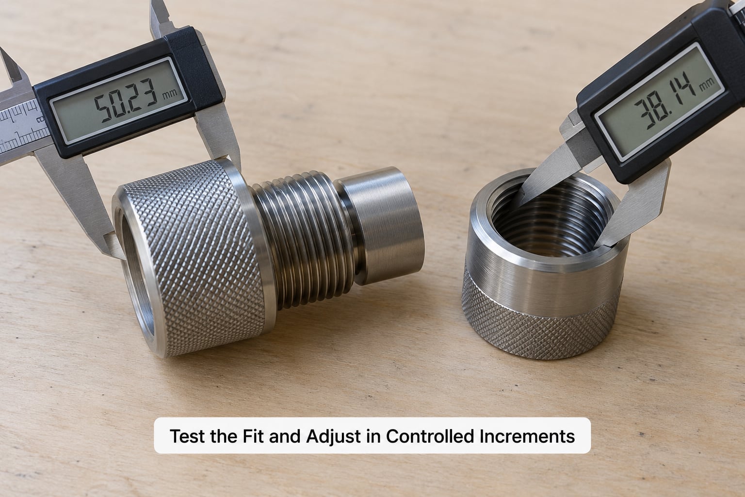
Make the coupon small: 10 to 15mm long, four to six threads of engagement, and print the male and female halves on the same plate in the same orientation they will use in the real part. Same plate matters, because it keeps both halves at the same temperature and the same Z height.
Measure three things before you twist anything. The male major diameter at three points along its length, the female minor diameter at the mouth and at the back of the engagement, and the pitch by measuring over ten thread turns and dividing. A thread with the right diameter and the wrong pitch will bind at exactly one depth, and that symptom always points at the helix rather than the clearance.
Then classify what happened:
- Too loose, wobbles and backs off under finger pressure. Reduce clearance by 0.05mm per face and print again.
- Too tight, will not start by hand and needs pliers. Add 0.05mm per face, and check that your offset actually applied to the internal face.
- Starts then strips, crumbling flanks. Clearance is roughly right; the walls are too thin, the infill too low or the layer bonding too weak. Add a wall loop before you add clearance.
- Binds in one spot only. That is geometry, not tolerance: check the seam position, the elephant foot, and whether the axis really printed vertical.
- Not repeatable, worked last week and not now. Dimension drift. Re-measure, then re-run flow compensation rather than chasing the model.
Change one thing at a time and write down what you changed. I keep a running note of clearance per face for each machine and material, because the same model on a different filament needs a different number and I would rather look it up than discover it at midnight.
Print and Inspect the Final Assembly
Run the real part with the settings that worked on the coupon. Break the supports, brush the thread valleys out, and check the flank with a fingernail: any ridge you can catch is a ridge that will stop the mating part halfway in.
Start every joint by hand and finish it by hand. Over-tightening a printed thread strips it far more often than any load does, and cross-threading usually happens because a part was pushed straight down instead of started on the helix. Friction heat is the other quiet cause of binding, so if a fit goes tight after twenty cycles, stop and look for plastic smeared onto the flanks rather than reaching for pliers.
Watch the thread root. Cracks radiating from it, a flattened crest, or a screw that turns while the printed part stays put all mean the load exceeded the joint. Strength comes from wall thickness around the thread and from engagement length, and adding both is far more reliable than tightening harder. Anything safety-critical, structural or load-bearing should take a metal fastener or a heat-set insert; printed threads are fine for panel closures, jigs, camera plates and camera cages, and they are not fine for anything that hurts someone if it fails.
Common Mistakes
Zero clearance. The parts are dimensionally identical on paper and the printer has already made them oversize by a few hundredths. Offset the face.
Treating a library nut STL as a finished hole. The STL was modelled at nominal size, so cutting it straight in gives you a zero-clearance fit before the printer adds its own error.
Too few perimeters. One or two wall loops on a helix means a thread flank with almost no material behind it, and it will shear the first time it is tightened properly.
Poor orientation. Printing the axis flat because the part fits the bed better gives you a wavy flank and a diameter you cannot repeat. Rotate the part or split the print.
Aggressive compensation on an uncalibrated machine. Scaling the model by 1.5 percent because the threads are tight hides the real error somewhere else in the part. Calibrate first.
Testing diameter but not pitch. A wrong pitch binds at one specific depth and gets misdiagnosed as a tight fit, which is why measuring ten turns is worth the thirty seconds.
Choosing the material by strength instead of by stability. Printed threads fail along the helix when layer bonding is poor, and PETG snaps there more often than PLA does despite being the tougher filament. ABS and ASA warp, which turns a round bore into an oval one.
In short: coarse pitch, 0.2 to 0.3mm per face, low layer height, three walls, axis vertical, coupon first, one change per test.
Frequently Asked Questions
Can a normal FDM printer make threads that actually screw together?
Yes, on any filament printer, provided you start from a coarse thread standard, add roughly 0.2 to 0.3mm of radial clearance, and test a short coupon before printing the full part. Fine threads and anything under M4 are unreliable. Printed threads also have a low stripping strength, so use them for closures and jigs rather than load-bearing joints.
Do I need CAD software with a dedicated thread generator?
No, but it saves a lot of work. Fusion 360 has a Thread tool with an ISO Metric profile, FreeCAD has a thread primitive, and OpenSCAD has a threads library. The critical detail is that you must model real helical geometry and tick Model Thread in Fusion 360, or your exported STL will contain no thread at all.
Should 3D-printed screw threads be printed vertically or horizontally?
Print the thread axis vertical for most parts. Each layer then has the same profile in plan view, which gives continuous perimeters and a bore that stays round. Laying it flat puts more of the flank along the layer lines for strength, but the profile shifts between layers and the fit stops being predictable. Use vertical unless load matters more than fit.
What clearance should I use for my first FDM thread test?
About 0.2mm per face, which is 0.4mm of diametral clearance, on M4 and M5 threads. Increase to 0.25 to 0.30mm per face on M6 and M8. That is radial clearance on the internal opening, not on the external thread. Print a 10 to 15mm coupon with four to six threads of engagement and adjust by 0.05mm per face from there.
Why does my threaded part fit at the opening but bind deeper inside?
A fit that works at the mouth and jams further in is almost always pitch or concentricity, not clearance. Measure ten thread turns and divide to check the pitch, then look at whether the bore is running out or the axis printed tilted. Elephant foot on the first layers also closes the mouth clearance while leaving the deeper part loose. Learning how to print threads that screw together starts with measuring pitch, not with changing offsets.
Start With a Calibrated Test Pair
Do this first, in this order. Pick a coarse standard thread, model a short male and female pair with about 0.2mm of clearance per face, print both halves on one plate with the axis vertical at a 0.1mm layer height, then measure the major diameter, the minor diameter and ten turns of pitch before you try to screw them together.
That coupon takes ten minutes and tells you the real clearance number for your machine, your filament and your layer height. Put the number in a note, then scale it. When the parts do mate, the finish is smooth, resistance stays even from the first turn to the last, and you can remove and refit them a dozen times without a single crack appearing at the root. If one area binds while the rest turns freely, you have a geometry problem to fix, not a tolerance problem.
The clearance numbers above still hold in 2026, so run the coupon method every time you change filament. Add a chamfer at the thread mouth and reach for a heat-set insert the moment a joint starts carrying real load.