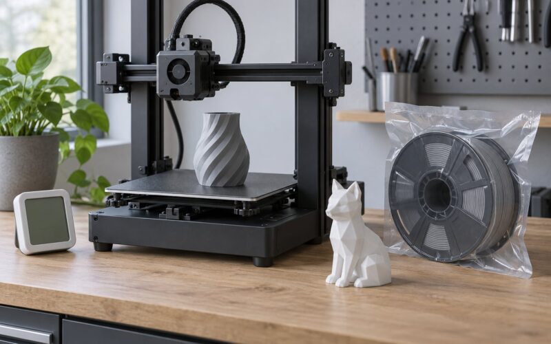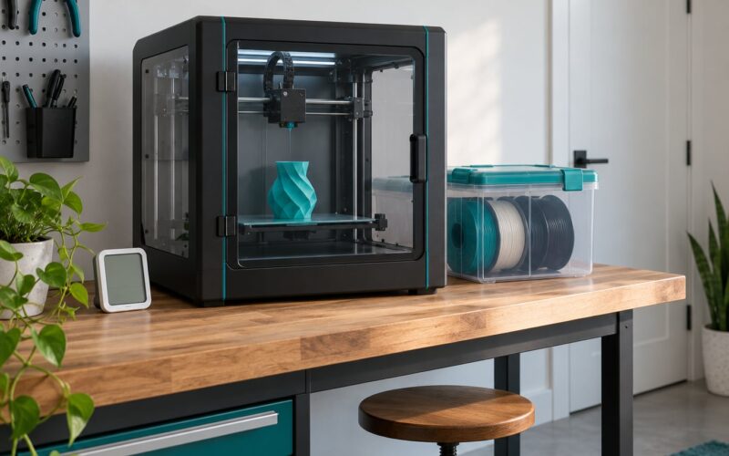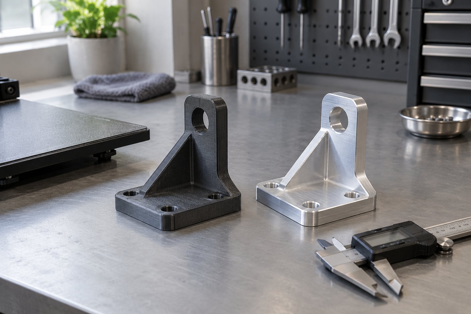
Design for additive manufacturing basics come down to a handful of decisions you make before the printer ever starts: which way the part faces the build plate, how thick the walls are, where the unsupported overhangs sit, and whether you design the supports in or design them away. A model that looks perfect on screen can still fail on the plate, so the aim of DfAM is to move those decisions upstream where you can control them.
The guide walks through those decisions in the order you actually meet them, starting from the part’s function and load path and finishing with a repeatable preflight check before the file leaves your computer.
Table of Contents
- What Is Design for Additive Manufacturing?
- The Design for Additive Manufacturing Workflow
- Core Design for Additive Manufacturing Basics
- How the rules look on four common parts
- How to Choose a Build Orientation
- How to Design Supports, Holes, and Small Features
- How to Match the Part to the Material and Process
- Design Checks Before You Send a Part to the Printer
- Frequently Asked Questions
- What are the most important design for additive manufacturing basics?
- What minimum wall thickness should I use for a 3D-printed part?
- How do I choose the best orientation for a 3D-printed part?
- When should I design supports instead of changing the geometry?
- Are 3D-printed threads and holes reliable without machining?
- How do I account for tolerances in additive manufacturing?
- Conclusion: Start With Function, Then Optimize the Print
What Is Design for Additive Manufacturing?
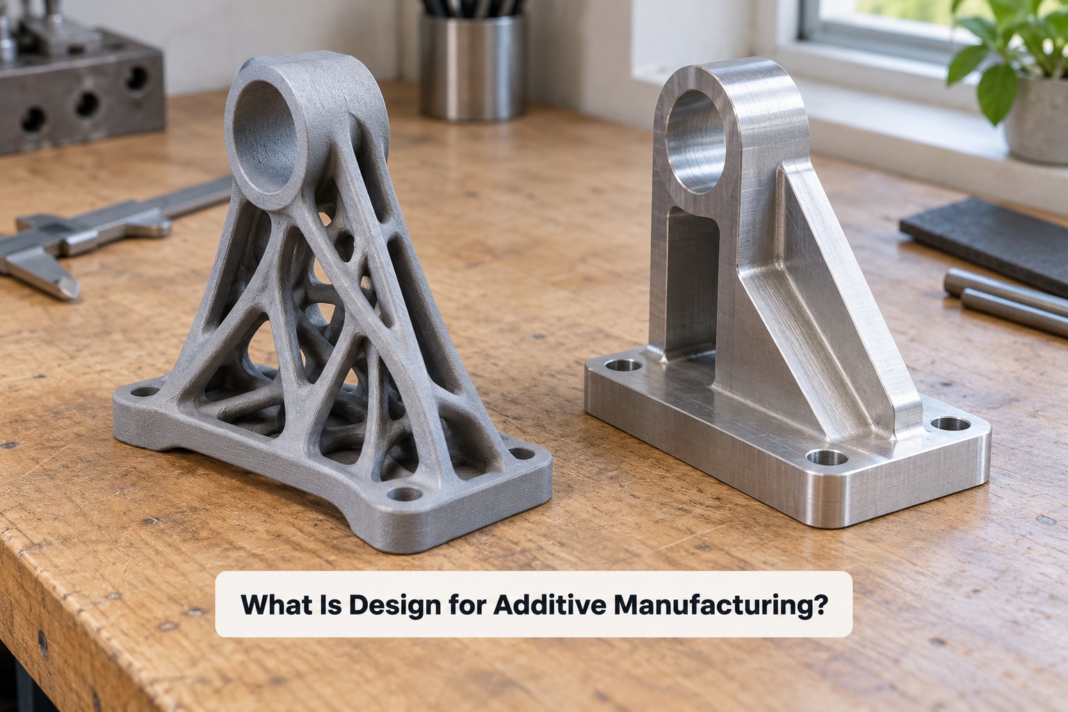
Design for additive manufacturing (DfAM) is the practice of designing a part around how the chosen additive process builds material layer by layer, rather than around the rules of machining or molding. You set wall thickness, overhang angles, part orientation, support strategy and tolerances to match what the printer can actually produce, so the finished part is strong, accurate and cheap to finish.
Conventional design starts with a solid block or a steel mold and removes material until the part emerges. That approach rewards thick walls, sharp internal corners, tight tolerances and geometry that is simple to reach with a cutter. Additive manufacturing runs the logic in reverse: material is deposited, fused or cured in place, so thin ribs, curved surfaces, internal channels and integrated fasteners become easy, while anything requiring sharp edges between layers, clean holes or isotropic strength becomes awkward.
The decisions that matter most, in rough order of how often they bite:
- Part orientation, which decides layer direction, support volume, print time and finish quality.
- Wall thickness and feature size, which have to match what your nozzle, laser or light can resolve.
- Overhang angle, the single biggest cause of failed prints for new designers.
- Support strategy, whether a region is self-supporting, needs printed supports, or can be redesigned so it never touches the plate.
- Tolerance and clearance strategy, because holes and pins behave differently in every process.
- Material choice, since stiffness, temperature limit and layer adhesion differ far more than people expect.
Design for 3D printing is the same discipline with hobby-scale numbers attached. Industrial DfAM adds qualification, repeatability and traceability on top, but the geometry reasoning underneath is identical.
The Design for Additive Manufacturing Workflow
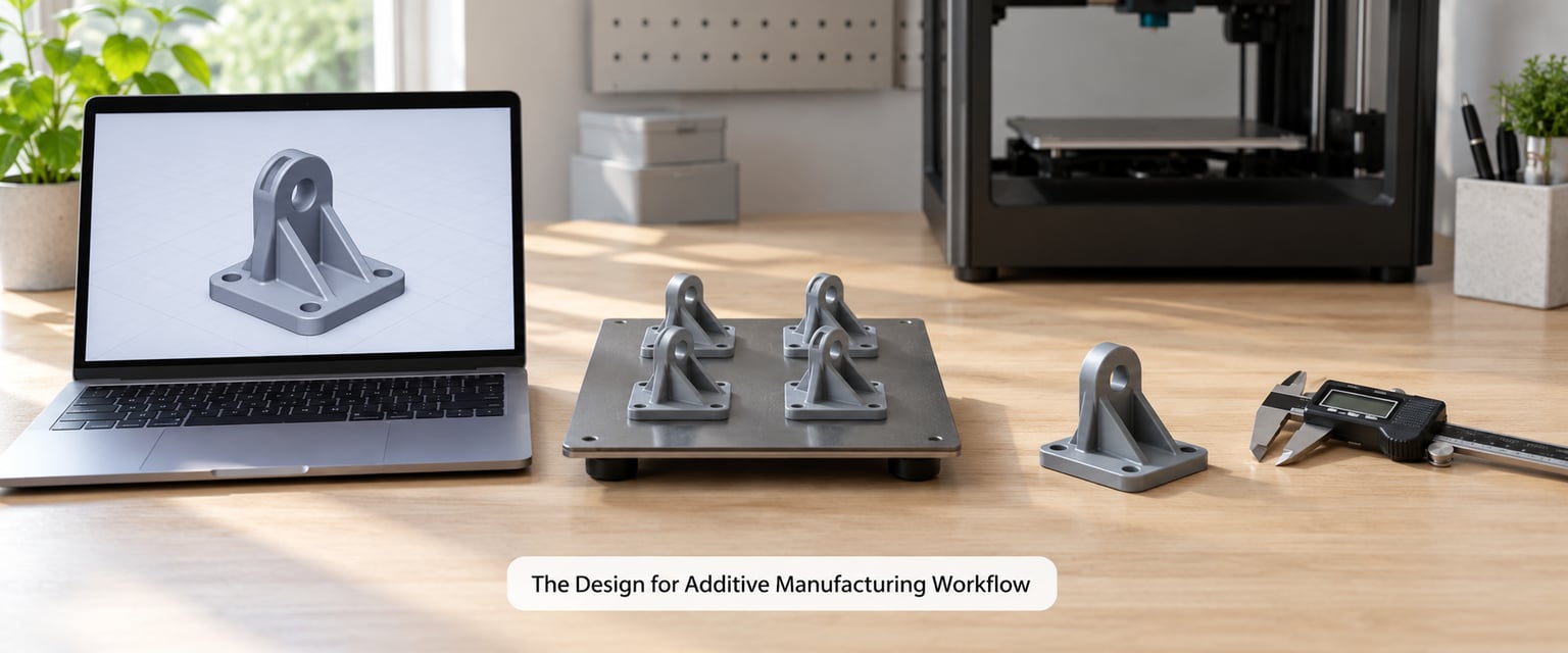
A repeatable workflow removes most of the guesswork. Most failed prints on a hobby machine trace back to a decision skipped somewhere in this sequence.
- Define the function and constraints. Write down what the part does, where the load enters, the working temperature, the material it touches and the surface that has to look good.
- Draw the load path. Put material where force travels. A bracket with ribs radiating from the bolt hole is far stronger than a solid block of the same outline.
- Pick the process. FDM for speed and size, resin for detail and smooth faces, powder bed for production parts without supports, metal processes when the load and temperature demand it.
- Add DfAM geometry. Chamfer the top, break the internal corners, size holes for the process, thicken thin features to whole extrusion widths.
- Choose the orientation. Lay the part down so the dominant load runs along the layers and the visible faces point up or down.
- Plan supports and the build arrangement. Decide what is self-supporting, where interface marks will land and how the part nests on the plate.
- Export, slice and inspect. Export STL or 3MF, run the slicer, and read every warning it produces before committing hours of machine time.
- Print a test coupon and measure. A small part with the same walls, same orientation and same material tells you more in 40 minutes than an afternoon of guessing.
| Stage | What to check | Failure it prevents |
|---|---|---|
| Function | Loads, temperatures, environment, mating parts | A part that prints but cannot do its job |
| Process selection | Detail, size, quantity, strength, finish | Choosing resin for a large draft, or FDM for a fine gear train |
| Geometry | Wall thickness, hole sizes, overhangs, corners | Delamination, blocked holes, sagging overhangs |
| Orientation | Layer direction under load, upward-facing cosmetic faces | Weak Z-direction failure, sanding-heavy finish |
| Supports | Contact points, interface marks, accessibility | Support scars on a finished face |
| Slice review | Warnings, wall count, infill, adhesion area | Hours of filament wasted on a known fault |
| First article | Measured holes, wall thickness, flatness with calipers | Discovering a bad fit only after full production |
Core Design for Additive Manufacturing Basics
Eight rules cover most of what a beginner needs. Every number below is a starting point, not a law, because they shift with nozzle size, layer height and material.
- Design walls in multiples of the extrusion width. A 0.4 mm nozzle with a 0.2 mm layer height deposits paths 0.4 mm wide. A wall of 1.2 mm lands on three clean paths; a wall of 1.3 mm leaves a sliver that prints ragged and peels. Round to the nearest whole path.
- Treat overhangs as a 45-degree question. FDM handles roughly 45 to 50 degrees from vertical reliably on a well-tuned machine. Steeper than that and the layer has nothing to rest on, which shows up as droop, stringing or a failed bridge.
- Round the top, break the corners. A 45-degree chamfer on the topmost edge and a small fillet on every internal corner are cheap to model and they remove the two most common stress concentrators and overhang traps. Sharp 90-degree internal corners print fine and crack later.
- Make holes slightly oversize and pins slightly undersize. Printed holes come out a little small from extrusion shrinkage and hole-out artifacts. Opening a 4.2 mm hole in the model for a 4 mm pin is normal practice on FDM.
- Orient for the load, not for the plate. Layers bond to each other far better than they bond across, so put the direction of maximum stress inside the layer plane. A hook printed flat along its length is several times stronger than the same hook printed standing on its end.
- Design the supports out first, then support what remains. Split a part into printable sections joined by pegs and sockets, chamfer downward-facing surfaces, and angle anything that overhangs. Printed supports cost material, time and post-processing, and every one of them leaves a scar.
- Set tolerance from the layer, not from the CAD default. Layer height sets the resolution ceiling. A 0.2 mm layer on a curved face produces visible stepping, and a press fit designed to 0.05 mm of clearance simply will not exist after printing.
- Leave room for post-processing. Printed surfaces carry a characteristic texture from layer lines. If a face must look finished, orient it up or down and sand it. If it must be dimensionally exact, plan for drilling, reaming or a light skim after printing.
How the rules look on four common parts
A mounting bracket. Start with the bolt hole as the load entry point and run ribs outward at 45-degree spacing rather than thickening the whole plate. Cut a chamfer on the underside so it sits down without support, and set the mounting holes about 0.2 mm oversize for FDM.
A living hinge. These work because the material flexes repeatedly within its elastic range. Give the flexing section a consistent width around 1 to 1.6 mm, keep it free of infill by setting its top and bottom shells to a single layer each, and print it so the bend runs along the layer plane rather than across it. Vary the width through the hinge and you get a controlled spring rate.
A small gear or sprocket. Teeth are the hardest feature on a printed part because they are thin, sharp and loaded. Favor a larger root circle over finer teeth, add a lightening hole pattern in the web, and check that the tooth thickness clears the minimum feature rule for your process. Resin handles this far better than FDM because the layer resolution is much finer.
An electronics enclosure. These are the friendliest first project: no heavy loads, plenty of flat surfaces, tolerance needs that are generous. Chamfer the lid rim for a print-in-place fit, keep screw bosses at a whole number of extrusion widths, and orient the lid so its visible top face is flat on the plate.
How to Choose a Build Orientation
Orientation is the decision with the widest blast radius. Change it and layer direction, support volume, print time, dimensional accuracy, surface finish and appearance all move at once.
Strength. Layer adhesion means a part is strongest within a layer and weakest between layers. FDM materials typically show a noticeable drop in interlayer strength, and the effect grows as layer height rises. Resin is more isotropic than people expect, though the layer direction still matters. Orient so that the biggest and most constant load runs parallel to the plate.
Support volume. Anything facing downward needs support unless it can bridge. An orientation that turns a downward-facing bracket into a flat-down bracket can cut support material by most of its volume and shave hours off the print.
Surface finish and accuracy. Faces parallel to the build plate come out smooth, flat and dimensionally accurate. Faces at an angle show layer stepping and shrink in size. Small holes lose their shape when they run horizontally, so drill them along Z instead.
Time. A tall part printed upright can take many times longer than the same part laid flat, mostly because of the layer count over the full height.
A workable decision method: rank the part’s faces by how much load each one carries, by whether the surface is visible to a user, and by how many downward-facing areas it has. Then try two or three orientations in the slicer preview and compare layer counts and support volume before committing. The slicer preview takes a minute and settles arguments faster than a forum thread.
Warping and delamination are orientation and geometry problems as much as slicer problems. A wide flat footprint, a chamfered perimeter and a part that stays within the printer’s usable volume all reduce the thermal stress that curls the corners off the plate.
How to Design Supports, Holes, and Small Features
Supports exist to hold geometry that would otherwise fall. Good DfAM reduces them in two ways: reshape the part so more of it is self-supporting, and place the supports that remain where they are easiest to hide or remove.
Make geometry self-supporting. A 45-degree chamfer under an overhang replaces a support tower. Splitting a part into two interlocking halves removes support from the mating face entirely. Printing an assembly in pieces and bonding it afterwards is sometimes the honest answer, especially when the joint needs to be serviceable anyway.
Place supports where they hide. Contact points on the bottom of the part leave an unavoidable mark. Put them on faces that go against another part, or on surfaces you will sand or fill afterwards. Interface-layer settings in most slicers control how visible those marks are.
Size holes and pins for the process. FDM holes need roughly 0.1 to 0.3 mm of extra diameter and pins a similar amount less. Resin shrinks more in some directions and benefits from a slightly larger allowance plus a short exposure that pre-cures the opening. SLS holes print close to nominal but still gain a slight roughness at the wall, which affects sliding fits.
Respect minimum feature thickness. A feature thinner than the extrusion width will be weak, may not stick to the layer beneath it and often prints with gaps. Ribs, webs and gussets follow the same rule as walls. Where a part needs strength, prefer two or three ribs spaced apart over one thick web; a thin rib pair is often both lighter and stiffer in the direction you care about.
Do not trust printed threads for repeated assembly. Threads printed in FDM have a rounded crest and a rough flank, and they wear quickly. Use a printed pilot hole with a metal or heat-set insert, or accept printed threads for a part that is disassembled a handful of times. Threads in resin hold better but still gain polymer on the flank with every cycle.
Which numbers you treat as fixed depends on your machine. The relationship between wall width, nozzle size and layer height holds across most FDM printers. A specific overhang angle is a property of your extruder, filament and cooling, so test a small angled coupon before you commit a full part to it.
How to Match the Part to the Material and Process
Process choice sets the rules. A minimum feature that works in resin is meaningless on a coarse FDM machine, and a design that prints beautifully in nylon powder needs a different support and hole strategy than the same part in PLA.
| Process | Typical materials | Suited to | Main design constraints |
|---|---|---|---|
| FDM (material extrusion) | PLA, PETG, ABS, ASA, TPU, nylon, carbon-filled blends | Large functional parts, jigs, enclosures, drafts | Thickest walls and features, overhangs near 45 degrees, layer lines on every face, anisotropic strength |
| SLA / DLP (vat photopolymerization) | Photopolymer resins, castable and toughened blends | Fine detail, tight fits, smooth faces, patterns | Supports under most downward geometry, brittle unless a toughened resin is used, UV sensitivity, thermal limits |
| SLS (powder bed fusion) | Nylon PA12, PA 11, TPU, some metals | Production runs, complex internal channels, batch parts | No support structures, but trapped powder in enclosed voids and horizontal holes; coarse surface finish |
| Metal powder bed fusion (PBF, DMLS) | Aluminum, titanium, stainless steel, nickel alloys, maraging steel | End-use aerospace, medical and tooling parts | Supports needed on down-facing surfaces, residual stress and distortion, heat treatment and machining after the build |
The numbers below are typical starting points for well-tuned equipment. Check them against your own machine and material, because a worn nozzle or a cold chamber moves all of them.
| Process | Minimum wall | Smallest reliable feature | Support-free overhang | Typical accuracy |
|---|---|---|---|---|
| FDM, 0.4 mm nozzle | 0.8 to 1.2 mm (two to three walls) | about 0.6 mm | 45 to 50 degrees from vertical | roughly plus or minus 0.2 mm on a well-tuned machine |
| SLA / DLP resin | 0.4 to 0.8 mm | about 0.2 to 0.3 mm | limited; supports usually needed beyond a few degrees | roughly plus or minus 0.05 to 0.15 mm |
| SLS nylon | 0.6 to 1.0 mm | about 0.4 to 0.6 mm | close to horizontal, with trapped powder | roughly plus or minus 0.1 to 0.2 mm |
| Metal powder bed fusion | 0.3 to 0.5 mm | about 0.2 to 0.4 mm | limited; supports and machining usually required | roughly plus or minus 0.1 mm as built, tighter after finishing |
Material choice changes the design as much as the process does. PLA prints beautifully and behaves badly near a heat source. PETG adds a little toughness and heat resistance and is more prone to stringing. ABS and ASA need an enclosure and a warm chamber because the layer bond depends on it. Nylon is dimensionally unforgiving since it absorbs moisture and swells, so wall thickness and clearances need extra allowance.
Metals behave differently again: they are strong in every direction once machined, yet the as-built surface carries roughness that usually needs finishing, and thermal stresses distort long thin features during the build.
Whatever you choose, remember that a printed part is rarely as stiff in every direction as its CAD model implies. Standard FDM test coupons show interlayer strength well below in-layer strength, and the gap narrows as layer height drops and as material bonds improve.
Design Checks Before You Send a Part to the Printer
Run this list before every job that matters. It takes about ten minutes and catches most problems that would otherwise appear hours later.
- Dimensions. Confirm the part fits inside the usable build volume, not just the stated one, with room for supports and clearance from the plate edge.
- Orientation. Check that the dominant load runs along the layers and that no cosmetic face is angled.
- Walls and ribs. Confirm every wall is a whole number of extrusion widths and every rib clears the minimum thickness for the material.
- Overhangs. Scan the slicer preview for anything steeper than your machine’s tested limit, then fix it with a chamfer or a split.
- Holes and clearances. Verify that press fits have more clearance than the nominal gap because printed holes shrink.
- Supports. Count the support contact points and ask where each scar will land.
- Heat and materials. Confirm the part is not asking a PLA part to sit near an engine bay or a hot nozzle, and that a chamber-heated material has a heated chamber.
- First-layer adhesion. Keep a skirt or brim wherever the footprint is small or the part is tall and narrow.
- Ejection. FDM parts need a small clearance or a chamfer to come off the plate, and resin prints need enough draft or a deliberate break-away tab.
- Post-processing. Decide now whether the part needs sanding, filling, drilling, tapping or heat treatment after printing.
Slicer warnings are useful, not infallible. Warnings about thin walls, overhangs and unsupported regions catch real problems far more often than they cry wolf, but slicers do not know the load your part carries. A 0.8 mm wall that holds a lid is not the same as one that holds a clamp.
Validate with a coupon. Print a small block that uses the same material, the same layer height and the same wall count as the real part, then measure it with calipers and try a pin into a test hole. That single check replaces most of the argument about tolerances, and it costs a fraction of a failed large print. On a professional line the same idea runs as first article inspection, where every critical dimension gets checked and recorded before the full batch runs.
New processes appear every year, and what held for the machine you owned two years ago may not hold now. Re-test the numbers whenever you change material, nozzle or printer, and write down what worked in your own log. By 2026 the rules people argue about online have barely changed, because they come from how material behaves rather than from any one machine.
Frequently Asked Questions
What are the most important design for additive manufacturing basics?
The fundamentals are orientation, wall thickness, overhang angle, support strategy, tolerance planning and material choice. Orientation sets layer direction and finish, walls must match the extrusion width, overhangs beyond roughly 45 degrees need support on FDM, and clearances must account for how the process shrinks holes. Get these six right and most first prints succeed.
What minimum wall thickness should I use for a 3D-printed part?
On a typical desktop FDM machine with a 0.4 mm nozzle, start at two to three extrusion widths, or about 0.8 to 1.2 mm, and round wall dimensions to whole nozzle widths. One wall holds light, non-structural parts. Resin prints reliably at 0.4 to 0.8 mm, SLS nylon at 0.6 to 1.0 mm, and metal powder bed at 0.3 to 0.5 mm.
How do I choose the best orientation for a 3D-printed part?
Orient the part so the largest and most constant load runs within the layer plane, downward-facing surfaces become short chamfers or flat faces, and cosmetic faces lie flat on the plate. Compare two or three orientations in the slicer preview and check layer count, support volume and the direction of any small holes. Finishing time usually follows print time on orientation choice.
When should I design supports instead of changing the geometry?
Design supports when the geometry genuinely cannot be printed otherwise, such as a downward-facing internal shelf in a sealed housing. Change the geometry when a chamfer, a split into two parts, a print-in-place joint or a rotated orientation can remove them. Printed supports add material, time and scars, and support removal is often the longest step in the whole build.
Are 3D-printed threads and holes reliable without machining?
Printed threads work for occasional assembly but wear quickly on FDM because the crest is rounded and the flank is rough. For anything repeated, print a pilot hole slightly undersize and use a metal or heat-set insert. Printed holes need extra diameter, roughly 0.1 to 0.3 mm on FDM, and should be drilled or reamed when a true sliding fit matters.
How do I account for tolerances in additive manufacturing?
Treat layer height as your resolution limit, because surfaces at an angle shrink and stepped features vary by more than the nominal number suggests. Design press fits with clearance of a few tenths of a millimeter and sliding fits with more, then print a small coupon in the same material and measure it. Machine critical features after printing when accuracy truly matters.
Conclusion: Start With Function, Then Optimize the Print
The first action for a beginner is smaller than it sounds: write down what the part does, where the load enters and which surface has to look good. Those three answers fix orientation, support needs and finish before you open the slicer.
- Define the function and load path first. Put material where force travels, not where a sketch put it.
- Select the process and material second. Those two choices set your minimum wall, minimum feature, overhang limit and tolerance allowance.
- Validate the riskiest geometry third. Print a small coupon with the same walls, orientation and material, measure it with calipers, then scale up.
Every rule in this guide is downstream of those three steps. Get them right and the rest is practice.