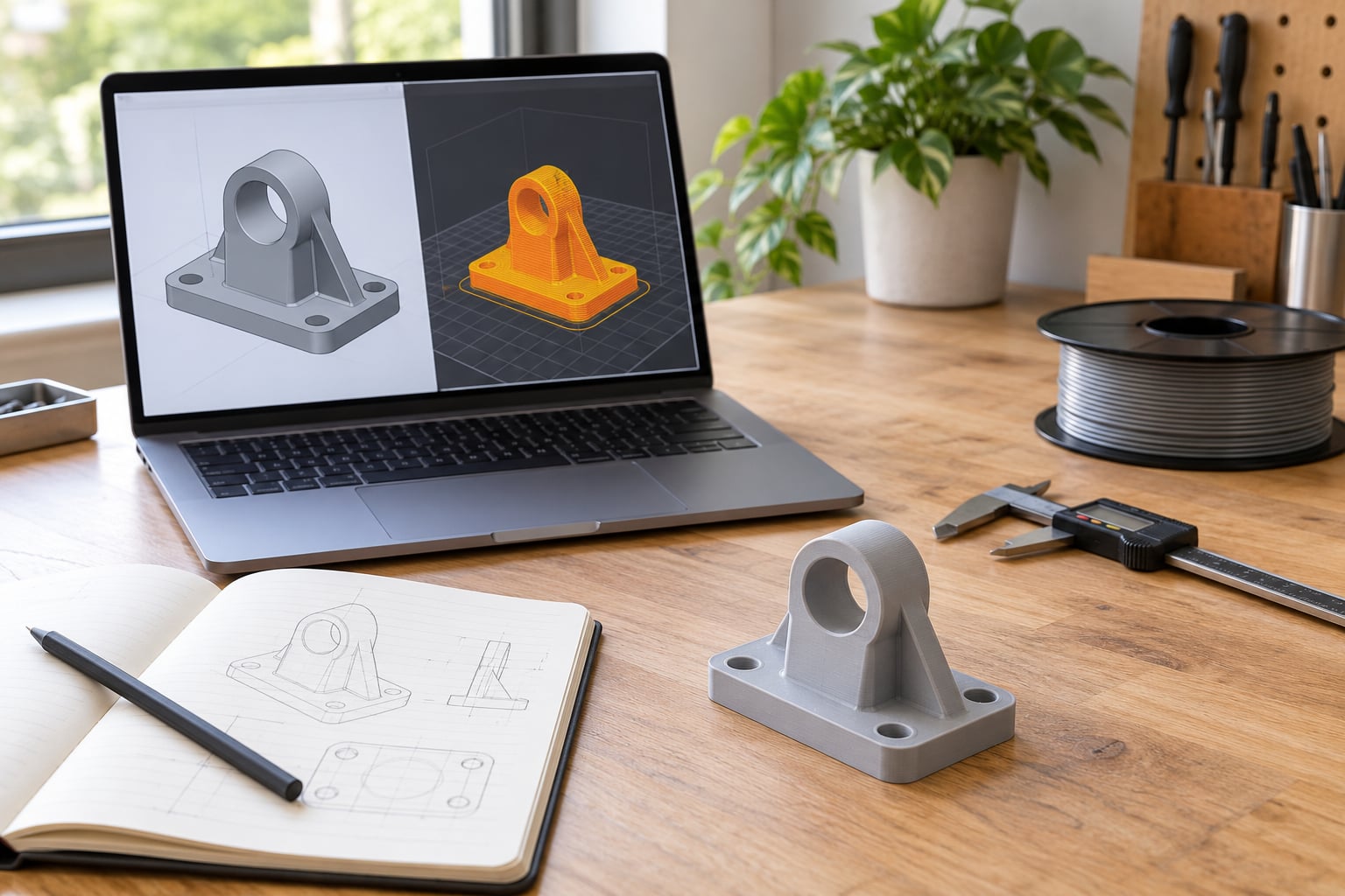
Rapid prototyping is the practice of getting a physical part or model in your hands fast enough that changing your mind is still cheap. The rapid prototyping workflow explained in this guide runs in eight steps: define what the prototype must prove, model it in CAD, run a manufacturability check, choose process and material, prepare the file for the machine, print or machine it, finish it, then test it and feed the results back into the next version.
Most of the time lost in prototyping is not lost at the printer. It is lost upstream, when nobody decided what question the part needed to answer, and downstream, when a promising design gets pushed toward production tooling before anyone has checked whether it survives contact with real materials and real tolerances.
This guide walks the whole path, technology-neutral, the way it actually runs on a desk or in a small studio. Numbers quoted are typical ranges from how additive and subtractive processes behave in general, so treat them as starting points rather than guarantees.
Table of Contents
- What Is a Rapid Prototyping Workflow?
- How Do You Turn an Idea into a Testable Prototype?
- How Do You Prepare the CAD Model for Rapid Prototyping?
- Which Prototyping Method Should You Use?
- What Are the 7 Types of Additive Manufacturing?
- How Does the Rapid Prototyping Workflow Move from Build to Test?
- How Do You Test and Validate the Prototype?
- How Do You Iterate Without Wasting Time or Money?
- When Is a Rapid Prototype Ready for Production?
- Frequently Asked Questions
- Is rapid prototyping a skill?
- What are the 7 types of additive manufacturing?
- What are the steps involved in prototyping?
- Is rapid prototyping the same as 3D printing?
- How long does a rapid prototyping cycle take?
- What files do I need to send to a rapid prototyping service?
- Conclusion: Start With the Question the Prototype Must Answer
What Is a Rapid Prototyping Workflow?
A rapid prototyping workflow is the repeatable sequence that connects a design decision to physical evidence and back again. The word that matters is workflow, not the machine. A printer is one step in a loop of define, model, prepare, build, finish, test, and revise, and the loop is what makes the process rapid.
Ordinary prototyping assumes a long cycle. You draw it, order tooling, wait, assemble, and only then discover the part does not fit. Rapid prototyping compresses that loop by replacing hard commitments with cheap, throwaway evidence. You test the assumption that is most likely to be wrong, not the whole product at once.
Here is the eight-step sequence in full, which is the version most teams actually run:
- Define requirements and decide what the prototype must prove.
- Build the concept and model it in CAD.
- Run a DFM or DfAM check and set tolerances.
- Choose the process and the material.
- Export and prepare the file for the machine.
- Print, mill, or cast the prototype.
- Post-process and finish the surface.
- Test it, record results, and iterate.
Each step has an input, an output, and a decision attached to it. The decision is the part people skip, and skipping it is why prototypes arrive at the next stage unproven.
| Stage | Input | Output | Decision made here |
|---|---|---|---|
| Requirements | Problem statement, constraints, user needs | One sentence on what the prototype must prove | Is this the riskiest assumption worth testing? |
| Concept and CAD | Requirements, prior versions | Parametric model with named dimensions | Is the geometry plausible enough to build? |
| Manufacturability check | CAD model, target process | Annotated model with wall, overhang and tolerance notes | What has to change to be buildable at all? |
| Process and material | Open risks, required accuracy | Chosen technology, material and orientation | Which method answers the question at lowest fidelity that still answers it? |
| File preparation | Export, slicing or CAM setup | Machine-ready file and toolpath | Where will supports, warping and shrinkage go? |
| Build | Machine-ready file, material | Raw part | Was the first section sound, and do the numbers hold? |
| Post-processing | Raw part | Finished, dimensioned part | Is the finish good enough to test, or only to look at? |
| Test and iterate | Finished part, test plan | Pass/fail result and change list | Change one thing, or go back to requirements? |
One note on terminology before we go further. Rapid prototyping is the umbrella term. Additive manufacturing, usually called 3D printing, is the largest branch of it, and CNC machining is subtractive. Both sit inside rapid prototyping because both cut cycle time. Search results for this topic mix in software and UX prototyping, which is a different discipline entirely, and this guide stays on the physical side.
How Do You Turn an Idea into a Testable Prototype?
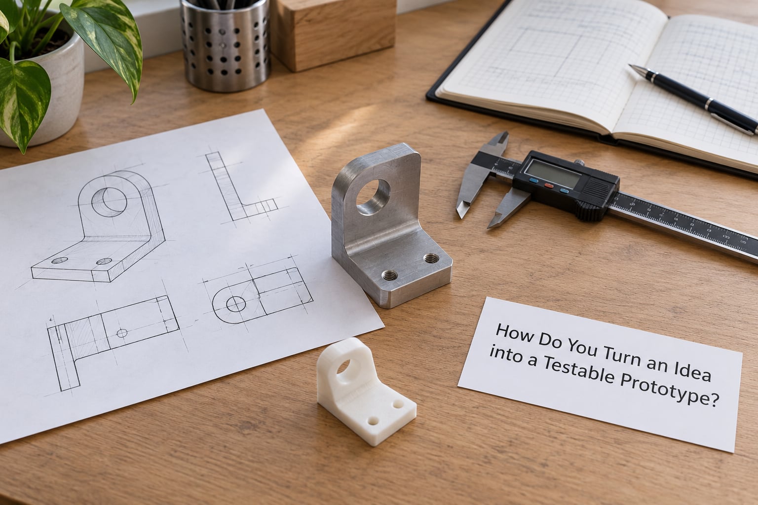
Start by writing down the problem, not the object. One sentence, in plain language, that describes what is failing today. Most wasted prototypes happen because the maker decided on a shape before deciding on a question.
Then list your assumptions and mark the riskiest one. Assumptions come in a few flavours: does it fit, will it hold load, is it comfortable to use, does it look right, does the mechanism move. A housing that has to sit in a user’s hand has an ergonomics risk. A bracket carrying a static load has a strength and deflection risk. Those two are tested with completely different parts.
Set pass and fail criteria before you build anything. Numeric, written down, and attached to the test. Pass criteria turn a subjective argument in a meeting into a measurement at the bench, which is the whole point of doing this quickly. If a hole needs to be 12.1 mm for a 12 mm shaft, write that down and put a caliper on it afterwards.
Now pick the lowest-fidelity method that can still answer the question. Fit questions are answered well by an FDM print in PLA or PETG. Surface and appearance questions usually need a resin print. Strength questions need a material that behaves like the real one, or an honest calculation alongside the print. A question about feel and shape can be answered with a foam block cut with a knife, which takes fifteen minutes and saves a day.
Write a short test plan. Who tests it, with what equipment, measuring which dimensions, and what happens after a failure. The normal loop in practice is measure, draw, fail, reprint, repeat. The iteration count is usually higher than a polished case study admits, and the people who plan for five revisions are rarely the ones stuck on revision twelve.
For multi-part ideas, prototype the sub-assembly that carries the risk first and leave the rest as solid blocks. Somebody building a gripper will machine the jaw interface and print the body crude, because the interface is what decides whether the tool works at all.
How Do You Prepare the CAD Model for Rapid Prototyping?
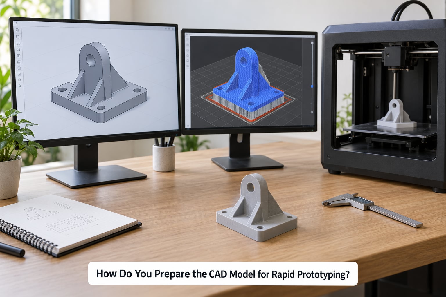
This is the step most guides skip, and it is where hours disappear. The CAD file you design with and the file the machine consumes are not the same file, and the gap between them is where print failures live.
Simplify what the process cannot reproduce. Threads, tiny fillets, logos and text under a millimetre, and cosmetic details add build time without telling you anything new. In a resin print, anything under 0.3 mm is a rounding error you will spend time cleaning for nothing. Sharp internal corners that would carry stress in a moulded part also carry stress in a printed one, because the process cannot add fillets there without redesign.
Give walls real thickness. FDM parts usually want a minimum of three extrusion widths per wall, commonly 0.8 to 1.2 mm for a 0.4 mm nozzle, and thin ribs on tall sections need more, not less. Resin prints are fine thinner. A wall that is theoretically 0.8 mm wide can come out at half that if it is not an even multiple of the nozzle, which is exactly how a housing stops accepting its own lid.
Think about overhangs and draft before you think about supports. A support is a cost and a surface defect you have to clean off afterwards, and support scars land on the surfaces people look at. Angling a feature, splitting a part into sections, or rotating the model so the worst overhangs point down often removes supports completely. Holes printed as open teardrop shapes instead of perfect circles are a cheap, widely used trick that also removes the support entirely.
Set build orientation with a purpose. The layer lines in an FDM part are weakest between layers, so orient the part so the load runs within the layers rather than across them. A tall column printed on end will snap at the first shock; the same column printed on its side is far tougher. Orientation also decides which faces carry visible texture, so for an appearance-critical part, point the best face upward.
Decide your tolerances, and write them down. Typical FDM dimensional accuracy on a consumer machine sits around 0.2 to 0.5 mm, resin lands nearer 0.1 to 0.2 mm, and SLS and metal powder processes run tighter, roughly 0.1 mm. Those are process realities, not settings you can talk your way around. If two features need to mate, either design them to the process you actually have, or leave clearance, and record which you did. FDM parts also behave anisotropically, meaning they can be tighter in one direction and looser in another, so do not design a press fit that only works in X.
Export, then check the mesh. STL remains the universal exchange format, though 3MF carries units, colour and material information that STL throws away, so prefer 3MF when your slicer supports it. After export, look at the part in the slicer or repair tool and check for non-manifold edges, holes, self-intersections and stray floating geometry. A 0.1 mm defect at a hole edge will not matter, and a flipped or self-intersecting face will fail the build an hour in.
For CNC work the equivalent is CAM: pick a setup, confirm the block of raw material has enough margin around the part, verify the tool can reach every feature, and decide what holds the workpiece down before the first cut rather than after. Then send both processes the same respect: a model with no version label gets reworked twice, once by mistake.
Which Prototyping Method Should You Use?
Choose by the question, not by the technology that is fashionable. The table below is a selection guide, not a ranking.
| Method | Detail and surface | Typical turnaround | Relative cost | Material limits | Best used to answer |
|---|---|---|---|---|---|
| FDM (filament) | Coarse layers, 0.1 to 0.3 mm layer height | Hours to a couple of days | Lowest | Thermoplastics, some engineering grades | Fit, form and low-load function |
| Resin (SLA/DLP) | Fine detail, smooth but needs washing and curing | Several hours plus post-processing | Low to medium | Mostly brittle photopolymers, tough variants exist | Surface finish, detail, appearance review |
| SLS powder | Good detail, slightly grainy, no support marks | One to several days | Medium | Nylon and other engineering powders | Strong, functional, production-like parts |
| CNC machining | Very good accuracy and finish on metal or plastic | Days, longer for complex set-ups | High per part | Raw block size and tool access | Tolerance, strength and real-world material data |
| Laser cutting | Flat parts only, crisp edges | Hours | Low | Sheet thickness and material | Flat patterns, enclosures, panel layout |
| Vacuum casting or silicone moulding | Near-injection finish, small batches | Several days including mould | Medium to high | Needs an accurate master model first | Handling several copies of one design |
| Foam, clay or card mockup | Very rough, fast to change | Minutes to an hour | Minimal | Shape only | Size, ergonomics, layout and form |
| Screen and paper mockup | No physical part at all | Hours | Minimal | Interfaces and flows only | Screen flow, naming, sequence |
What Are the 7 Types of Additive Manufacturing?
The seven process families that cover almost all additive work are: material extrusion, vat photopolymerization, powder bed fusion, material jetting, binder jetting, sheet lamination and directed energy deposition. Material extrusion is FDM and FFF, the filament and pellet route most makers own. Vat photopolymerization covers SLA and DLP, where liquid resin is cured by light. Powder bed fusion covers SLS for polymers and DMLS or SLM for metals, where a laser or electron beam binds powder layer by layer. Material jetting drops liquid material droplets, binder jetting binds powder with a printed agent, sheet lamination cuts and bonds pre-made sheets, and directed energy deposition feeds wire or powder into a focused heat source, usually for metal repair or cladding.
How Does the Rapid Prototyping Workflow Move from Build to Test?
The build stage is where planning turns into a result, and it is worth treating as its own discipline rather than pressing print and walking away.
Pick the material for the question you are answering, not for the colour. PLA is fast and stiff but brittle and heat-sensitive. PETG is tougher and more dimensionally stable, which makes it the safer default for fit checks. Nylon prints well but absorbs moisture and warps unless it is dried. Resin gives detail and needs careful washing, curing and handling. Choosing the wrong one is not a small mistake; it produces a part that fails under a load you expected it to carry.
Set the process parameters, then watch the first layers. On a filament machine the first three or four layers decide whether the part sticks to the bed and whether the first layer is squashed or floating. On resin, watch the first few millimetres for suction and for the part pulling away from the build plate. On CNC, the first cut on a sacrificial or face pass tells you about clamping and datum setup. If the start is wrong, stop the job. Ten minutes of observation saves a night of failed material.
Inspect for defects with the process in mind. On printed parts look for layer separation, delamination, stringing between features, warping at corners, cracking at sharp internal corners, and holes that came out oval. On machined parts look for chatter marks, tool marks across a sealing face, burrs and part-to-part variation. On cast or vacuum-formed parts, look at flash, sink marks and warp.
Measure against your written criteria, not against how the part feels. A caliper catches the obvious fit errors for most fit checks and costs very little. Where a real dimension matters and the part is complex, a 3D scan compared against the CAD file shows deviations a caliper will miss, and it closes the measure-verify loop before the next build starts. Cheap dimension coupons, small test pieces of known geometry printed with the same settings as the real part, are an even faster check when you want to know whether your process is drifting.
Write down what happened. Material, settings, temperature, humidity, orientation, measured dimensions, what failed. Makers who keep a log of failed iterations stop repeating the same mistake, and the log is what makes the build repeatable by someone else. A revision record attached to the model file, not a note in someone’s head, is the difference between iteration and thrashing.
How Do You Test and Validate the Prototype?
Test against the criteria you wrote in step one, using the type of test that matches the risk you identified. Functional testing asks whether the mechanism does its job: does the lever move the full range, does the latch hold, does the gear mesh without binding. Fit testing asks whether parts assemble, with a real mating part rather than a mental one. Environmental testing asks about temperature, humidity, fluids, vibration and UV exposure. Usability testing asks whether a person can hold, reach and operate it, which is where foam and clay models still earn their keep. Visual testing asks only whether the appearance and proportions read correctly to the intended audience.
Do the cheap tests first. Fit and operation, then strength, then appearance, then anything involving people. A surface that looks perfect tells you nothing about a snap fit that will not close in cold weather.
Record failures precisely. Not the part did not work, but the latch released at 14 N instead of the 20 N required, on the third cycle, with the printed material at 0.8 mm wall. Vague feedback produces vague redesigns, and redesigns are where schedule and material go to die.
Know what your prototype can and cannot prove. A resin print in a general-purpose photopolymer proves geometry and appearance, but it is far more brittle and behaves differently under load and heat than the engineering thermoplastic you might specify for production. A filament print in PLA proves shape and rough fit and almost nothing about long-term strength. A CNC part in the real material proves fit, strength and tolerance far better than any print, and it is often worth the extra cost precisely because the answers transfer to production.
That distinction is the honest limit of the whole method, and it is worth stating plainly to whoever is asking for the prototype: printed parts are evidence, not substitutes. Where the failure mode would be dangerous or expensive in the field, test the real material.
How Do You Iterate Without Wasting Time or Money?
Feedback arrives in layers, and treating it all as equal is how a small project turns into twenty prints. Sort every comment into three buckets: safety and function, fit and performance, and appearance. Fix the top bucket first and resist polishing the third while the first is open.
Then isolate. If a sub-assembly fails, prototype only that sub-assembly. If a dimension is wrong, print a small coupon of that dimension rather than the whole part. If a feature is being questioned, build two variants of just that feature on one plate and compare them side by side. This is the single most effective way to shorten the loop, and the trade is simple: you build less, you learn more per gram of material.
Worked example. A bracket prototype keeps cracking at the fillet where the arm meets the base. Rather than reprinting the whole bracket with a larger fillet, print a flat coupon containing the arm, the fillet and the base at three different fillet radii, all in the same orientation and with the same wall thickness as the real part. Three small parts instead of three large ones, and the answer comes in one evening instead of three. The chosen radius goes into the CAD model, the model version goes up by one, and the change is logged with the measured result.
Choose the next fidelity level from what is still unknown. If the shape is now right and the question is how it feels in the hand, a faster and cheaper print is fine. If the question is whether it survives a drop test, fidelity stops mattering and material starts to. Building a higher-fidelity prototype than the open question needs is the most common form of waste in the whole workflow.
Keep a revision record. One model file per version, named with a revision number and a one-line note about what changed. Confusion about which iteration is being built is a common and entirely preventable failure, and it is worse than a print failure because nobody notices until the test comes back wrong.
When Is a Rapid Prototype Ready for Production?
A prototype is production-ready only when its behaviour predicts the behaviour of the real part. Most prints do not, and saying so early is more useful than a vague reassurance.
Check the material. A prototype in a different material from the production part has different strength, stiffness, thermal behaviour, creep and fatigue life. If you need load, temperature or long-term data, test in the real material, which usually means a machined part or a printed part in an engineering-grade equivalent with its data sheet attached.
Check repeatability. One good part is a sample. Build three or more with the same process and compare them dimensionally; variation between them is the honest tolerance of your process, and it is often wider than a single successful part suggests. Measure critical features on each one and record the spread.
Check surface finish, safety and documentation. Does the part have sharp edges, burrs or flash that would injure a user? Do cosmetic surfaces meet the standard the drawing states? Is there a drawing, a revision number, a material specification and a tolerance callout for each feature that matters? Can someone who was not in the room build this part again and get the same result?
Be clear about the handoff. The step from prototype to tooling belongs to a manufacturing review, not to the person who modelled the part. A review looks at quantities, unit economics, draft angles, parting lines, gate and ejector placement on a mould, and whether the design relies on features the chosen process cannot repeat at volume. The gap between a printed prototype and mass production tooling is a genuine confusion point, and naming who owns that review is the cheapest fix available.
For hardware teams that run formal builds, the same progression is usually described as EVT, DVT and PVT: engineering validation builds prove the design works, design validation builds prove it is manufacturable and meets its specification, and production validation builds prove the production line can build it repeatably. Rapid prototypes sit in and before that first phase. They are excellent at finding geometry and ergonomics problems, and they say very little about assembly-line variation.
One last point on the transition. Printing the same process you plan to mass-produce with, and printing a proxy in a cheaper process, are different strategies. Matching processes reduces the number of surprises at the production line and cost more up front. A proxy gets you an answer faster and defers some risk to the tooling stage. Know which one you chose, and be honest about which surprises the strategy defers.
Frequently Asked Questions
Is rapid prototyping a skill?
It is a set of skills rather than one. CAD competence, machine operation, material knowledge and basic measurement matter, and none of them needs a formal qualification to start. The workflow itself is the real skill: deciding what to test, choosing the cheapest method that answers it, and recording results. People who pick that up by making one part per week get competent faster than people watching tutorials.
What are the 7 types of additive manufacturing?
The seven process families are material extrusion, vat photopolymerization, powder bed fusion, material jetting, binder jetting, sheet lamination and directed energy deposition. Material extrusion covers FDM and FFF. Vat photopolymerization covers SLA and DLP. Powder bed fusion covers SLS for polymers and DMLS or SLM for metals. The other four cover droplet jetting, powder binding with a printed agent, cut-and-bond sheets, and metal fed into a focused heat source.
What are the steps involved in prototyping?
The rapid prototyping workflow explained here is eight steps long: define what the prototype must prove, model it in CAD, run a manufacturability check and set tolerances, choose process and material, export and prepare the file, build the part, post-process the finish, then test and iterate. The order matters less than the decision attached to each step. Skipping step one is the most common reason a prototype arrives at the test stage unable to answer anything.
Is rapid prototyping the same as 3D printing?
No, though most examples people see are 3D printing. Rapid prototyping is the goal and the workflow, and it can be reached by subtractive methods such as CNC machining, by vacuum casting or by a foam cut with a knife. 3D printing, or additive manufacturing, is one way of building the physical part. A CNC part can be more informative than a print when the question is about tolerance, strength or real material behaviour.
How long does a rapid prototyping cycle take?
For a desk-scale part, a day or two is realistic: an hour or two to model, a few minutes to prepare the file, several hours to build, and an hour to finish and test. More complex parts with post-processing, or a machined part with several set-ups, run to several days. The whole cycle is a loop rather than a single pass, so the useful number is the time per iteration, not the time to the first part.
What files do I need to send to a rapid prototyping service?
Send a watertight STL or 3MF, plus a PDF drawing that states the measurement system, scale, material, the critical dimensions with tolerances, the surfaces that matter cosmetically, and how the part will be used. Add a short note on orientation if you know a feature is load-bearing. If the design is confidential, ask about an NDA before sending anything, and agree a revision naming scheme so you can both tell which iteration is being quoted.
Conclusion: Start With the Question the Prototype Must Answer
The whole workflow compresses to three moves. Write down the riskiest assumption in your design, choose the lowest-fidelity prototype that can honestly test that one assumption, and record the pass-or-fail criteria before the machine starts. Everything after that is preparation, building and finishing, and the loop is only fast if each pass feeds the next version instead of starting over.
Do it in that order and the printer stops being the interesting part, which is roughly where it belongs. That is the rapid prototyping workflow explained here in two sentences, and it is enough to make the next version cheaper than the last one.