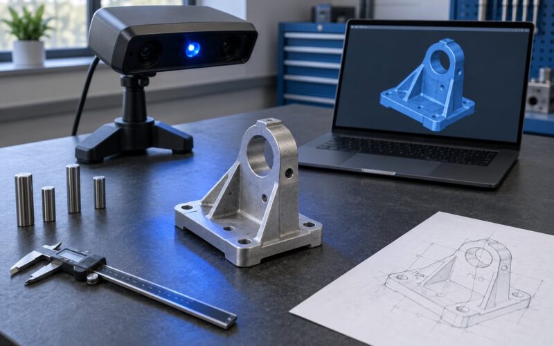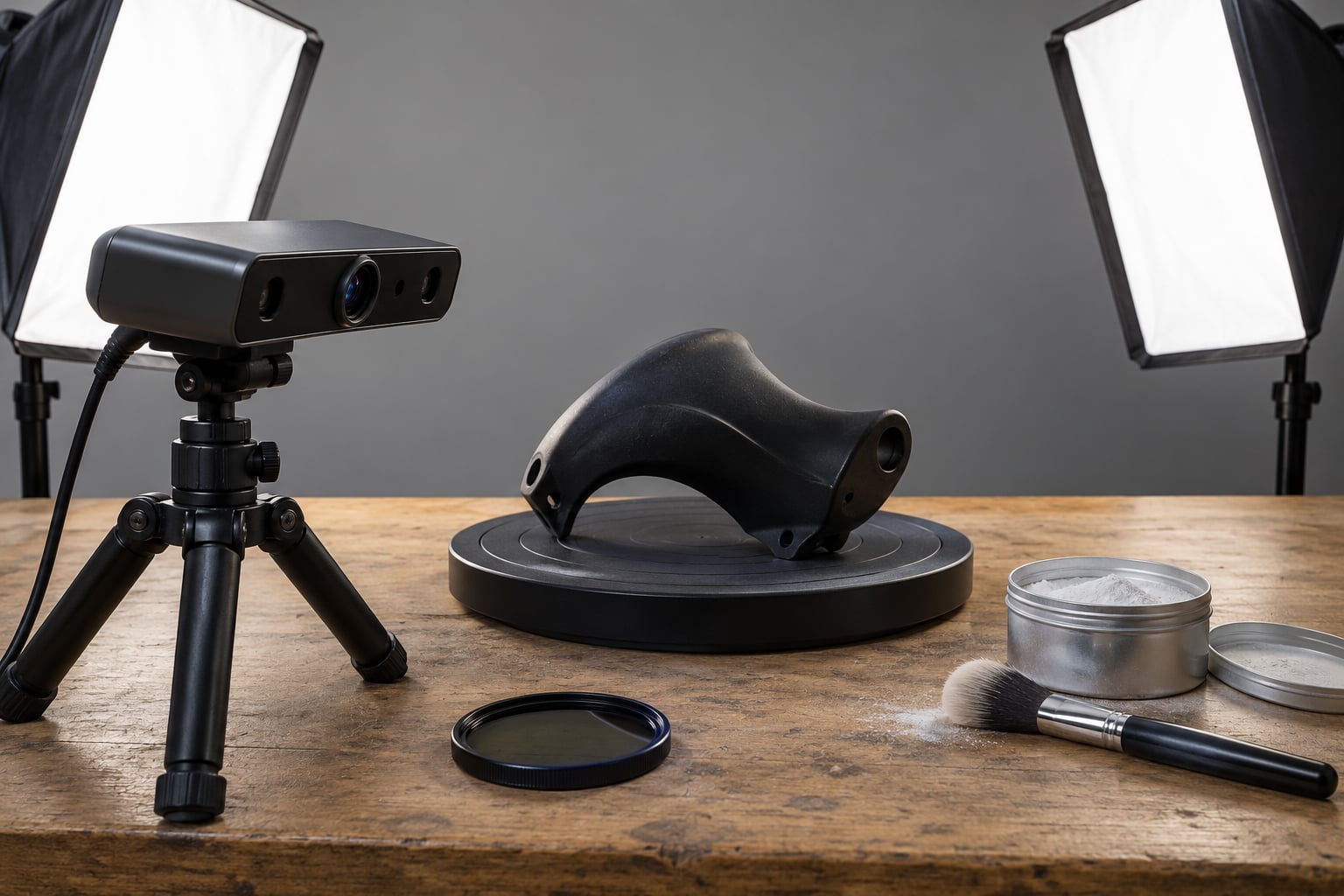
Knowing how to 3D scan shiny or black surfaces comes down to one idea: give the scanner a matte texture it can measure and stop reflected light from confusing it. Shiny finishes bounce the projected light back at the camera and blow out the exposure, while black plastic absorbs most of the scanner’s infrared light and comes back as a point cloud full of holes. Both problems have known fixes, and most of them cost a few dollars and about an hour of setup.
The order you fix things in matters more than anything else. Diagnose whether you are fighting reflection or low contrast, then deal with lighting, then exposure, then surface coating. Coating first with a thick textured paint is the most common mistake, and it is the hardest to undo.
Table of Contents
- What You Need
- Step-by-Step
- 1. Identify Why the Surface Is Failing
- 2. Prepare the Surface Without Damaging It
- 3. Control Reflections With Lighting and Polarization
- 4. Adjust Exposure, Contrast, and Scan Settings
- 5. Capture Multiple Angles and Maintain Alignment
- 6. Inspect the Mesh and Fix Missing Data
- 7. Clean Up the Scan for 3D Printing or Design
- Common Mistakes
- Frequently Asked Questions
- Can a 3D scanner scan a black object at all?
- Is spray paint or chalk spray safe on a finished part?
- Does cross-polarisation work for every 3D scanner?
- How much powder or matte spray should I use?
- What do I do when a shiny scan still has holes?
- Can I use my phone as a LiDAR scanner on a black surface?
- Conclusion
What You Need
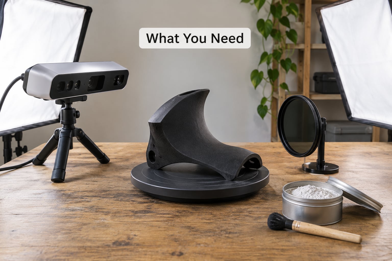
Most of the kit is optional. The one item you genuinely cannot skip is some way to kill the reflection.
- A scanner with exposure control or HDR capture. Automatic exposure on a black object is the single biggest cause of empty scans. Blue-light or multi-wavelength scan modes help a lot on dark plastic if your scanner has them.
- Diffuse, shadowless lighting. Two softboxes at roughly 45 degrees to the camera axis, or a light tent with a diffused panel. Direct sunlight is the worst option available, not the best.
- A tripod or fixed mount. A scanner that moves between frames cannot align. Mask the mount point so it does not appear in the reconstruction.
- A linear or circular polarising filter. Optional but close to essential for chrome and mirror finishes. Two polarisers, one on the light and one on the camera lens, remove almost all specular glare without touching the object.
- A removable matte coating. Scan developer spray, chalk spray, or a DIY powder mix. Thinish scanning spray is a real product category; the key word to look for is matte, not textured.
- Masking materials. Low-tack tape and removable film for keeping powder off polished edges, badges, threads and mating surfaces you do not want textured.
- Matte alignment markers or a reference plane. Glossy printed markers throw their own reflections into the solve. Matte black dots on matte white card, or a matte sheet of newsprint under a symmetric object, give the software something stable to triangulate against.
Cross-polarisation is not available on every scanner. Single-camera structured light scanners that project a pattern cannot always be filtered without blocking the projection itself, and phone photogrammetry can only be polarised if you shoot through a lens you can actually attach a filter to. Handheld laser triangulation scanners handle glare differently again, because the laser and camera are physically separated.
Step-by-Step
1. Identify Why the Surface Is Failing
Shiny and black fail for opposite physical reasons, and the fix for one makes the other worse. A mirror-finish surface throws a specular reflection straight back at the sensor: the camera sees a small, extremely bright hotspot instead of a broad, evenly lit area, so the exposure drops and the shape vanishes. A matte black surface does the opposite, absorbing almost all of the projected and infrared light and returning very little signal, so the software simply finds no features to track.
To tell them apart, put the object under one soft light and rotate it slowly in front of the live preview. Bright glare patches sliding across the surface mean reflection. A surface that stays flat, featureless, and empty no matter how you turn it means absorption.
Test with a printed reference plane underneath first. If the plane and the background scan cleanly while the object does not, the problem is the object’s surface, not your lighting or your settings. That test takes two minutes and saves an hour of guessing.
2. Prepare the Surface Without Damaging It
Clean the object first with a lint-free cloth and a little isopropyl alcohol. IPA here means isopropyl alcohol, not the beer, which is a running joke in scanning forums for a reason. Cleaning removes fingerprints and dust films, both of which create their own fake highlights.
Then apply a thin, even matte layer. The thickness target is roughly 10 to 20 microns, thick enough to kill the reflection, thin enough that no detail is lost. Anything thicker and you are modelling the coating instead of the part. Faux granite sprays and textured paints are the most common reason people give up on coating; they work technically and destroy the surface they were meant to reveal.
On a DIY mix, the most-endorsed recipe from scanning forums is baby powder or cornstarch suspended in isopropyl alcohol, sprayed or airbrushed on, allowed to dry to a chalky matte, then brushed off. A useful starting ratio is roughly one heaped teaspoon of powder per 100 ml of alcohol, adjusted until the mix sprays without separating. Shake the container constantly while spraying; the powder settles fast.
Other powders reported as workable include flour, powdered sugar, rice starch, matte grey water-soluble hairspray spattered with a paint-loaded toothbrush, and plain anti-perspirant. They vary a lot in how well they preserve detail and how easily they come off. Cornstarch leaves the thinnest, most even film. Flour clumps. Powdered sugar dissolves into a syrupy film that is hard to remove from seams.
Food and organic surfaces deserve their own approach. Freezing an organic object before scanning reduces reflectance and is a trick that keeps showing up on scanning forums, though it adds moisture and frost to clean up. For anything that will be washed or eaten, stick to a powder you know is food safe and keep the coating thin.
Skip coating on clear coat, polished paint, anodised finishes, chrome plating, and anything being restored or measured for tolerance unless the coating is fully removable and you have tested it on an inconspicuous area first. Mask those surfaces instead.
3. Control Reflections With Lighting and Polarization
Goal: suppress the specular hotspot while keeping enough side light to reveal shape and edge. Those two goals pull in opposite directions, and setups that kill every reflection tend to give you a flat, shadowless image that scans just as badly.
Put the main light at about 30 to 45 degrees off the camera axis, high enough to rake across curved surfaces. Add a weaker fill on the opposite side, at a third the power. This is standard product photography and it is the standard fix for glossy objects.
For a true cross-polarised setup, put one polariser over the light source and one on the camera lens, then rotate them relative to each other until the highlight on the object drops to its darkest. Almost all of the glare disappears. This method only removes reflection, so a genuinely black surface will still read as black, and you will still need a matte coating or more light for that case.
4. Adjust Exposure, Contrast, and Scan Settings
Automatic exposure is designed for average subjects, and a shiny object is not average. Set exposure manually and watch the histogram instead of the object. You want the specular peak to land below the clipping point, not touching the right edge of the graph.
Start by dropping exposure by one to two stops from the automatic value, then raise contrast if the software offers a contrast or gain control separate from exposure. If your software supports HDR or bracketed exposure, enable it: it lets you keep detail in the bright highlight and the dark shadow at the same time, which is exactly the situation a black glossy part puts you in.
Scan modes differ by technology. Photogrammetry cameras want the lowest exposure that still fills the surface with texture, plus a fixed white balance so frames match. Structured light scanners want the projected pattern bright and the exposure short. Laser triangulation scanners need the laser gain raised on dark surfaces and the surface tilted slightly so the return angle stays off the specular direction.
If the software offers a blue-light or multi-wavelength mode, switch to it. Blue light is far less absorbed by black plastic than infrared, so dark parts that return almost nothing in the default mode can return usable data in the blue mode. It is a user-facing setting, not a hidden one, and it is the first thing to try before you reach for a spray can.
5. Capture Multiple Angles and Maintain Alignment
Move or rotate in overlapping increments and keep enough overlap that the software can match frames. A common rule is 50 to 70 percent overlap for photogrammetry and turntable scanning. Below that you get registration failures, and above it you are just collecting redundant frames and burning processing time.
Photograph a test region first. One close pass over the hardest area, usually the most reflective curve, tells you in under a minute whether your settings are right, and it is far cheaper than a full capture followed by a failed solve.
For difficult parts, use a matte, non-reflective turntable or a fixture that holds the object at a fixed angle. Glossy turntables reflect the scanner back at itself and add their own holes to the mesh. Mask the base of the object and put it on newsprint if you have no turntable; a high-contrast fixed plane gives the solver something reliable to anchor to.
6. Inspect the Mesh and Fix Missing Data
Check the live preview and then the finished mesh for four specific defects. Holes and missing patches mean the capture failed there. Stretched polygons, sometimes called spikes, mean the software matched the wrong features. Phantom surfaces appear where a reflection was baked in as geometry. Duplicate geometry shows up as a bumpy or doubled shell.
Fix holes by rescanning that region with a changed setup, not by repairing it in software. Tilt the part, cross-polarise, add coating, or re-shoot at a different exposure. If you want to rescan one region later, place reference markers so the new data registers to the old.
Uneven point density, usually a band of dense and sparse data, comes from changing the angle of incidence too much between frames. Keep the working distance more consistent and keep the object in focus. Depth of field matters on close macro work; a thin slice of focus will lose the far side of a curved part.
One rule: never raise smoothing to hide capture errors. Smoothing hides a missing patch under invented geometry, and the invented part prints fine but is dimensionally wrong. If you smooth, smooth lightly, and only after the data is good.
7. Clean Up the Scan for 3D Printing or Design
Remove the coating first, while the object is still on the bench and while you can still see what you did. Dry powder brushes off with a soft brush. Alcohol-based mixes wipe off with a cloth dampened with isopropyl alcohol. Chalk spray and matte spray on a clean surface lift with a damp cloth. Check seams, threads, screw holes and undercuts afterwards, since powder hides there and it is the residue that will still be there in a year.
Then work on the data. Fill small holes in the mesh, decimate the polygon count if you are printing or handing the file to a renderer, check the scale against a known dimension, and orient the surface so it prints without supports where possible. Export as STL for printing, OBJ for general modelling work, or PLY when you want to keep the point colours and want to keep working in the cloud.
Keep the raw scan. The cleaned mesh is a derivative of data you cannot always regenerate, especially for a part you have since modified or repainted.
Common Mistakes
- Relying on one bright light. One hard source creates one hard hotspot. Use two diffused sources at opposing angles.
- Scanning in direct sunlight. It is recommended constantly and it is wrong: harsh shadows kill detail and the sun moves during a long capture.
- Using a thick textured coating. Faux granite and heavy paints fill in fine detail. Thin matte spray or powder only.
- Leaving reflections in the room. A white desk and a bright wall behind the object will reappear as phantom surfaces. Keep the surroundings matte and dim.
- Leaving exposure on automatic for a black object. The meter reads the black and lifts the exposure until the highlight clips. Set it manually.
- Moving too fast between frames. Insufficient overlap gives you an unregistered solve and stretched polygons. Slow down and check registration live.
- Using glossy markers. They throw reflections. Use matte printed markers or a matte reference plane.
- Repairing bad geometry only in software. Fill, decimate, and smooth will happily disguise a hole that should have been rescanned.
Frequently Asked Questions
Can a 3D scanner scan a black object at all?
Yes, with the right combination of settings. Black plastic absorbs most infrared light, which is why default modes return an empty point cloud. Try a blue-light or multi-wavelength scan mode first, since blue is far less absorbed. If that is not enough, raise the laser gain on a triangulation scanner, shorten the exposure, and add a thin matte coating. A black surface with no coating is the hardest case; a dark grey matte surface is much easier.
Is spray paint or chalk spray safe on a finished part?
Chalk spray and thin matte scanning spray are the safe options: both dry to a removable film that lifts with a damp cloth or a soft brush. Ordinary spray paint and textured faux granite sprays are not. They bond chemically, they add roughly 50 to 100 microns of texture, and they bury fine detail. On clear coat, polished paint, or anything being restored, mask the surface and coat only the areas you need.
Does cross-polarisation work for every 3D scanner?
Not all of them. It works best on photogrammetry setups and single-camera systems, where you can filter the lens and the light independently. On a projector-based structured light scanner, a filter on the camera can also block the projected pattern, which breaks the solve. Laser triangulation scanners separate the laser and camera by an angle, so they fight glare differently. Test cross-polarisation on your setup and keep the coating option ready.
How much powder or matte spray should I use?
Aim for 10 to 20 microns, which reads as a chalky matte finish with the original colour and detail still faintly visible. For a DIY mix, roughly one heaped teaspoon of cornstarch or baby powder per 100 ml of isopropyl alcohol works, sprayed thin in several light passes. Let it dry fully between passes. If you can see brush strokes or the coating has built up in crevices, you have gone too thick.
What do I do when a shiny scan still has holes?
Rescan the affected area rather than repairing it in software. Cross-polarise the lighting, shift the light and camera angles apart, raise the laser gain or enable HDR, then re-capture that region with reference markers so the new data registers to the original. Only after the data is complete should you fill small residual holes, and then decimate and smooth lightly. Smoothing over a missing patch invents geometry that prints wrong.
Can I use my phone as a LiDAR scanner on a black surface?
Phone LiDAR and photogrammetry apps handle black surfaces badly, because the camera and the projected light share the same optical path and a dark surface returns almost nothing. You can improve results by adding diffuse lighting, lowering exposure, and dust the object with a very light matte powder, then shooting with a fixed tripod and manual exposure. For anything that needs accurate geometry, a dedicated scanner will beat a phone by a wide margin.
Conclusion
Start by diagnosing which problem you actually have. If the preview shows glare sliding across the object as you turn it, you are fighting reflection, so fix the lighting and add cross-polarisation. If the object stays empty no matter how you turn it, you are fighting absorption, so switch to a blue-light or multi-wavelength mode, raise the gain, and add a thin removable matte coating.
Then work in order: lighting, exposure, coating. Do not reach for a thick spray first. Run one test region before you capture the whole object, keep the raw scan, and remove the coating while you can still see what you applied. Getting good at how to 3D scan shiny or black surfaces is less about special equipment than about diagnosing the right failure and fixing it in the right sequence.