If your slicer refuses to load a model, prints hollow shells, or fills the inside of a part with the wrong pattern, the cause is almost always non-manifold geometry. The mesh has an edge, vertex, or face that a printer cannot resolve, so the software has no way to tell inside from outside. Most defects are fixed in minutes once you know which of the five error types you are looking at.
The repair itself is not exotic. You inspect the mesh, find the offending edges, close the holes, weld the stray vertices, and re-check the exported file. The order matters, because repairing in the wrong sequence usually turns one small defect into a mangled surface and a much longer afternoon.
Here is the short version before the detail. First, duplicate the file and locate the bad edges in a mesh inspector rather than guessing from the solid view. Second, fix the cause: merge coincident vertices, fill open boundaries, remove self-intersections, and give zero-thickness walls real thickness. Third, export a fresh file and validate that exported mesh in your intended slicer, not the CAD program that made it. This guide walks through how to fix non manifold geometry for printing in that order, and the steps updated for 2026.
Table of Contents
- What You Need
- How to Fix Non Manifold Geometry Step by Step
- 1. Locate the Problem Areas
- 2. Check Scale, Orientation, and Volume
- 3. Merge Duplicate Vertices
- 4. Repair Holes and Open Boundaries
- 5. Resolve Self-Intersections and Thin Surfaces
- 6. Remesh Only When Necessary
- 7. Export and Validate Again
- Common Mistakes
- Frequently Asked Questions
- Do all non-manifold geometry errors need to be fixed before 3D printing?
- Can I repair a non-manifold STL file without recreating the CAD model?
- Why does my model become non-manifold only after exporting it to STL?
- Is non-manifold geometry a problem for resin printing as well as FDM printing?
- How can I stop non-manifold errors from returning after I fix the model?
- Conclusion
What You Need
You need four things, and one of them is a habit: work on a copy.
- The original model file. If you still have the CAD or mesh file the STL came from, keep it open. Many defects are far easier to correct in parametric CAD than in a triangulated mesh.
- The name of the tool that created it. Blender, Fusion 360, FreeCAD, Tinkercad, Maya, Rhino, or a 3D scanner. Knowing this predicts the defect before you even open the mesh.
- A way to inspect mesh statistics. Blender 4.x with the 3D Print Toolbox add-on, Autodesk MeshMixer’s Inspector, Microsoft 3D Builder on Windows, or the mesh checking command built into FreeCAD all report the same underlying numbers. If your slicer has its own check, that counts too.
- A backup copy of the STL. Every repair step in this guide is a step you may need to undo.
It is worth saying that a valid CAD body can still produce a broken STL. Triangulation during export splits curved surfaces into flat facets, and where two facets meet at a shallow angle you can end up with a T-junction, where the edge of one triangle sits in the middle of a neighbouring triangle’s edge. That single condition is behind a large share of the export errors people hit, and it has nothing to do with how carefully you modelled the part.
How to Fix Non Manifold Geometry Step by Step
1. Locate the Problem Areas
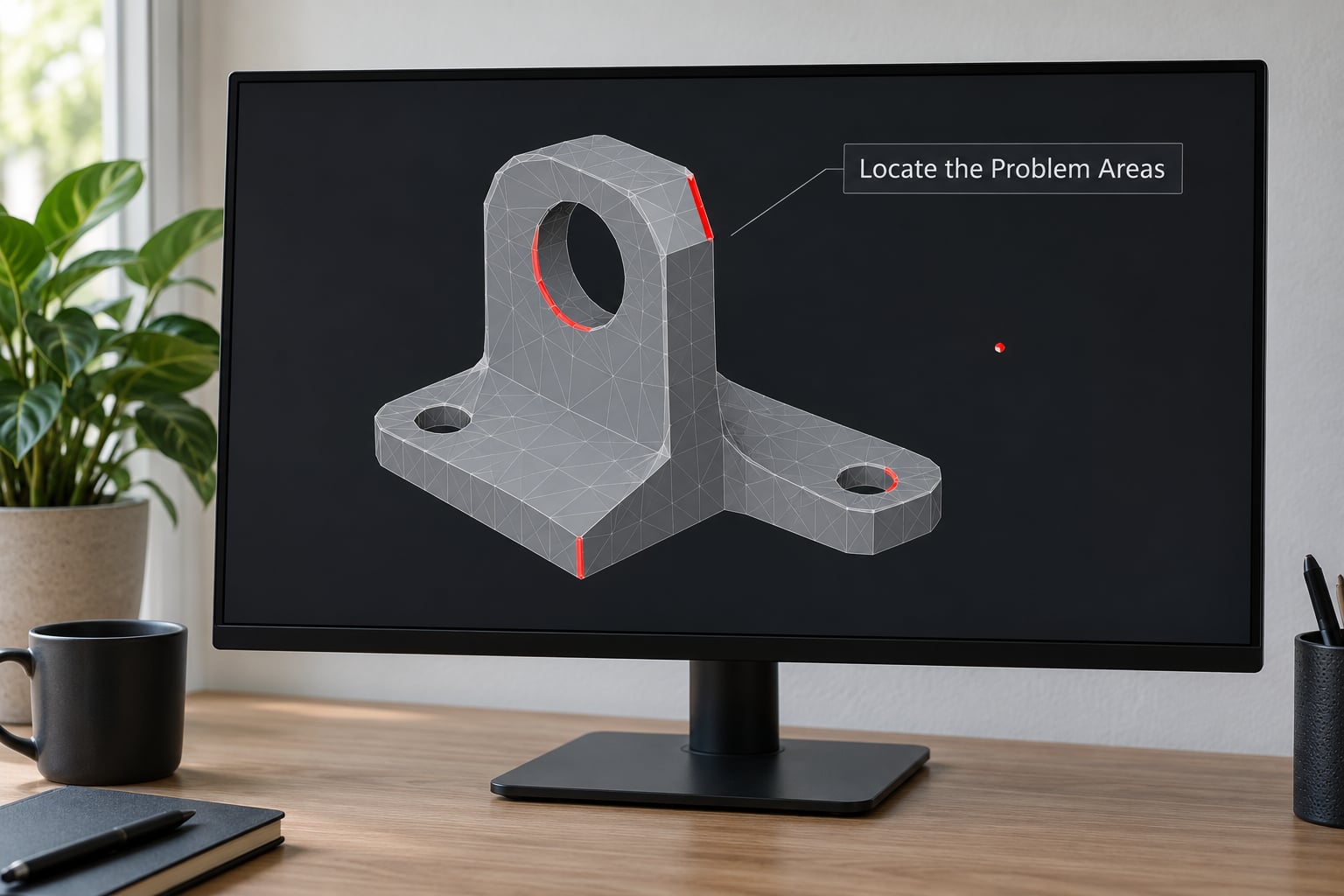
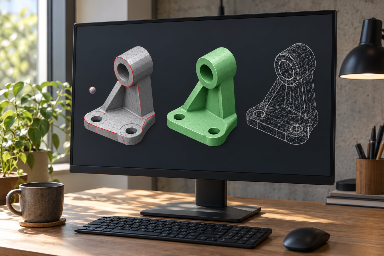
Start by duplicating the file, then turn on the defect display rather than staring at the shaded solid view. A model can look perfectly solid while carrying dozens of bad edges, because the shading hides exactly the boundary loops you need to see.
Work through four views in order:
- Wireframe view. Holes and open boundaries show as visible gaps in the lattice. A T-junction shows as one edge terminating mid-way along another.
- Mesh statistics. Face count, vertex count, loose geometry count, and the non-manifold edge and vertex totals. Write the numbers down before you touch anything, so you can tell whether a repair helped or quietly made things worse.
- Boundary edge selection. Most tools can select every edge that belongs to only one face. In MeshMixer the Inspector colours these separately from self-intersections; in Blender, edit mode with the face select method active, Ctrl+Alt+Shift+M selects non-manifold elements.
- The slicer error report. PrusaSlicer, OrcaSlicer, and Cura all name the problem when loading. Cura’s message, “Your model is not manifold,” points at the mesh as a whole, while Tinkercad’s export error, “Non-manifold Edges,” tells you the problem was created during export and the shapes in the design are the real culprit.
Zoom into each highlighted region individually. Most of the time the defects cluster in one place: a boolean seam, a thin rib, or the area where a subtracted cylinder met a wall.
2. Check Scale, Orientation, and Volume
Before editing geometry, confirm the model is actually a solid with a positive volume. A mesh that reports zero or negative volume has inconsistent face orientation, and a volume that is wildly off usually means a unit mismatch rather than a modelling error.
Scale is an application setting in most CAD programs, not a mesh defect. If your design was drawn in millimetres and the tool treats the file as centimetres, every dimension is out by a factor of ten, and repairing the mesh will not fix it. Check the export settings for unit interpretation before you assume something is wrong with the geometry.
Orientation matters for one specific repair: if faces point inward, auto-repair tools cannot tell a hole from the inside of a cavity. Recalculate outside normals in Blender with Mesh, Normals, Recalculate Outside, and in MeshMixer with Analysis, Normals, Recalculate. Do this before the hole-filling step, not after. If the model imports sideways, apply a rotation in the mesh editor and export again rather than rotating per layer in the slicer, which can introduce slice artefacts on tall parts.
3. Merge Duplicate Vertices
Two surfaces that touch without being welded are the classic cause of a non-manifold edge: each face has its own copy of the shared vertices, so every edge along that seam belongs to only one face. Welding the seam turns two open shells into one closed solid.
In Blender this is Edit mode, then Mesh, Clean Up, Merge by Distance. In MeshMixer it is Edit, Transform, Merge. Set the merge threshold below the smallest intentional feature on the part. If your thinnest rib is 1.2 mm, anything under about 0.1 mm is safe; a threshold of 1 mm will happily collapse that rib into a single face and change the part. Small values are the right default because a merge that does nothing is harmless, while a merge that is too aggressive is not.
After merging, look at the face count. A weld that removes a few thousand loose vertices without changing the triangle count is working. A weld that drops the triangle count dramatically has probably collapsed real geometry, and you should undo it and lower the threshold. Blender’s 3D Print Toolbox reports a live count of non-manifold edges, so you can watch the number fall as you work. That is the fastest reliable feedback loop for learning how to fix non manifold geometry for printing, and it is far more useful than staring at the viewport.
4. Repair Holes and Open Boundaries
After welding, anything still open is a genuine hole. Select the boundary loop and fill it. Blender’s F key, MeshMixer’s hole filling, and FreeCAD’s mesh refine all do a flat fill, which is correct for a flat plate with a small puncture and wrong for a curved surface where a flat cap will be visible in the finished part.
Be careful which openings you close. A cable pass-through, a vent slot, or the mouth of a phone stand is supposed to be open, and sealing it changes the design rather than repairing it. If an opening is intentional, leave it and accept that the part is not watertight, or redesign it so the opening is framed by thickness. That is usually the better fix.
Where the hole sits on a curved or angled surface, bridge the boundary loops with a strip of new faces rather than filling flat, and check the result from a low angle. Test the repaired patch by hiding everything else and viewing the region alone. A patch that looks acceptable in context often reads as a dent or a crease once you rotate it.
5. Resolve Self-Intersections and Thin Surfaces
Self-intersections happen when two parts of the mesh occupy the same space, and they are the defect auto-repair is worst at. Common sources are an un-unioned boolean in CAD, two overlapping bodies exported as one file, a mirrored modifier applied on top of existing geometry, or an AI-generated or scanned mesh that was never checked for thickness.
The right fix is almost always upstream. Return to the CAD model and combine the bodies with a union so the surfaces merge into one continuous shell. If there is no CAD file, delete the overlapping faces and rebuild that junction, or use a targeted boolean cleanup in the mesh editor rather than a global operation. Run a self-intersection check afterwards, because intersections often hide behind the hole you just filled.
Zero-thickness surfaces are the other half of this step. A face with no volume behind it, an open sheet used as a wall, or a wall thinner than your nozzle will print as nothing or as a single stray line. Give it real thickness. In Blender, the Solidify modifier adds a consistent shell with a set offset and even thickness, which is a cleaner result than filling the open sheet. If the thin wall is the result of a boolean that removed too much material, thicken the source solid instead.
6. Remesh Only When Necessary
Remeshing is the expensive option, so treat it as a last step. Voxel remeshing converts the surface into a volume grid, rebuilds it, and converts it back, which produces a guaranteed watertight result at the cost of all your sharp edges, holes, and fine detail. Everything becomes the same general radius.
It is worth it for a dense scanned mesh with thousands of small defects that no local repair will clear, and for an AI-generated body that came out as a blobby lump. Set the voxel size to roughly half the smallest detail you care about, and expect sharp corners to round off. Run a smoothing pass afterwards, but gently. Aggressive smoothing shrinks the part slightly, and for a fit-critical piece that shrinkage matters more than the defect you were fixing.
Never remesh a precise mechanical bracket to fix one hole. You will trade a five-minute repair for a model that no longer fits.
7. Export and Validate Again
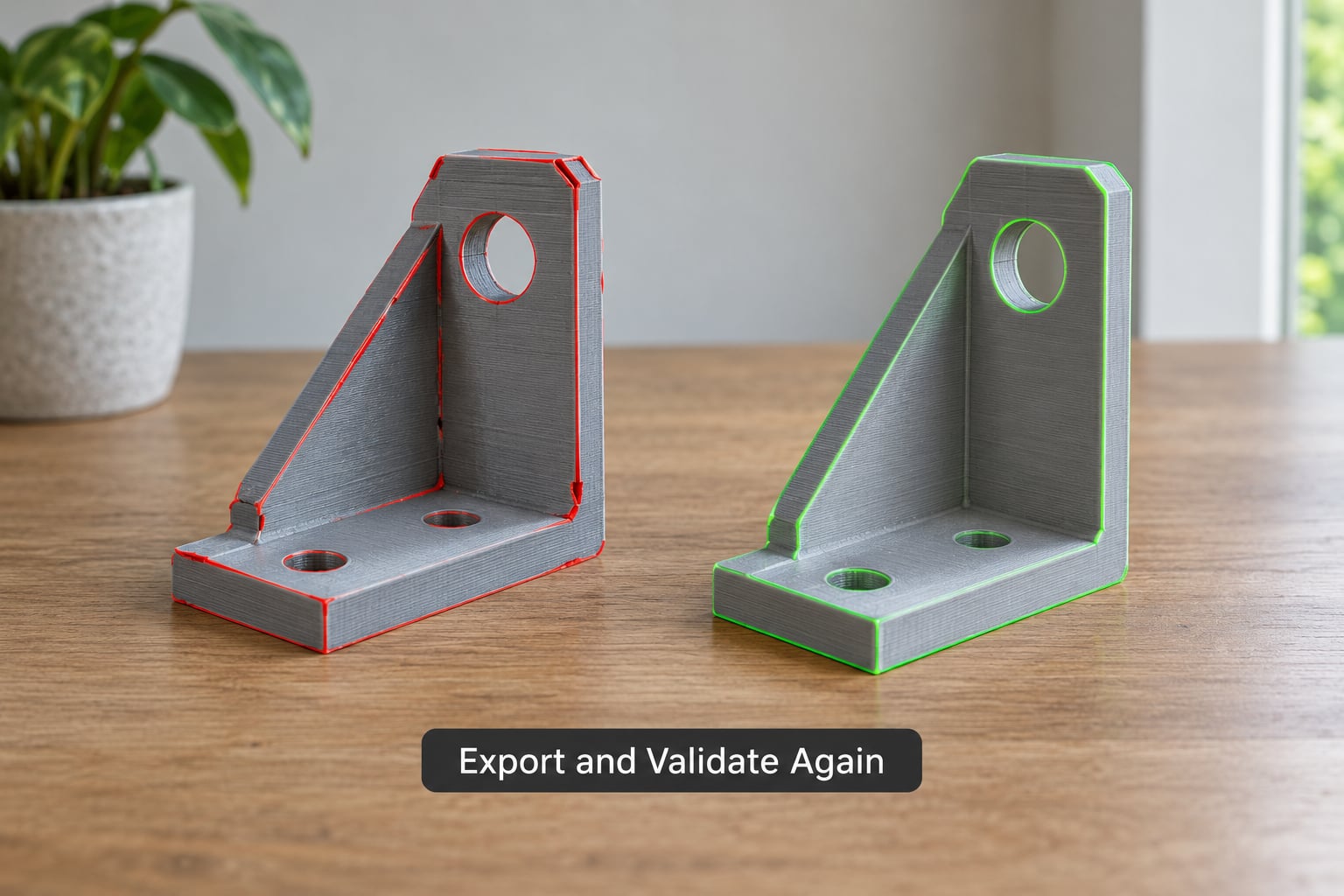
Export a fresh copy as STL in binary format, which is smaller and avoids the text-parsing quirks that produce stray faces, or as 3MF if your printer workflow supports it and you want units and colour preserved. Do not reuse the old STL. Repairs made in a mesh editor do not propagate back to the CAD file, and re-exporting from CAD will undo your work.
Now validate the file that will actually be printed, not the CAD source. Load the new STL into the intended slicer and check three things: no non-manifold warning appears, the object count matches what you designed, and the model sits the right way up on the build plate. Then look at the sliced preview, not just the model view, because the first and last few layers are where a thin or self-intersecting region becomes obvious.
Compare the outer dimensions against your design. A mesh that reports as watertight can still be wrong if an auto-repair step bridged a large opening with a flat panel. If the dimensions moved, you know which step did it.
Common Mistakes
Merging every vertex within a large distance. A generous merge threshold looks like a fast fix and quietly collapses thin ribs, small holes, and text on a surface. Set the threshold to a fraction of your smallest feature and check the face count afterwards.
Filling every opening. Auto-repair and one-click watertight tools cannot tell a defect from a design feature. Vents, cable slots, and open frames get sealed, and the printed part no longer does its job. Review each opening before you close it.
Ignoring the slicer report. When a slicer offers to repair on load, that is a convenient first pass for a small hole and a poor strategy for anything structural. It often resolves the symptom by regenerating geometry in the defect area, producing a bloated triangle count and a surface that no longer matches the design. Treat the automatic pass as a diagnostic: if the mesh still fails the inspector afterwards, the problem needs a real fix.
Changing export units to solve a geometry error. Scale and topology are separate problems. If a model imports at the wrong size, adjust the interpretation or scale factor in the slicer. If faces are inconsistent, fix the normals. Doing neither in the right order wastes hours.
Remeshing at too fine a resolution. A very small voxel size produces a huge file that slices slowly and still rounds off your sharp features, because the corners are being rebuilt from the same grid. Match the voxel size to the detail you need, not to the file size you want.
One last check before you commit filament: open the model in a second tool. Different programs test manifoldness slightly differently, and a mesh that passes in one can fail in another, particularly when zero-area faces are involved. If a print service or print farm rejects your upload outright, that check is the same one they are running, so it is worth doing before you pay for the rejection.
Frequently Asked Questions
Do all non-manifold geometry errors need to be fixed before 3D printing?
Sometimes you can print a model with a small number of non-manifold edges. If the defect is on a hidden internal surface, the slicer will usually fill the region with infill and the print will come out fine. If the defect is on an outer wall, near a hole, or involves self-intersecting geometry, the result is unpredictable: missing layers, wrong infill, thin spots, or a failed slice. Fix anything on the visible surface or anything the slicer warns about, and re-run the check before you start a long print.
Can I repair a non-manifold STL file without recreating the CAD model?
In most cases, yes. STL carries geometry but no parametric history, so you repair it as a mesh: select the bad edges, merge duplicate vertices, fill the open boundaries, recalculate normals, and re-export. Blender with the 3D Print Toolbox add-on and MeshMixer both handle this well. You lose the ability to change a dimension and have the model update, so if the file is a dimensionally critical part, rebuilding the source in CAD is the better long-term fix.
Why does my model become non-manifold only after exporting it to STL?
STL stores only a triangle soup with no concept of surfaces, volumes, or parametric relationships. During export your curved faces are triangulated, and where two facets meet at a shallow angle the export can produce a T-junction, where one edge terminates in the middle of another edge. That breaks the closed volume. Export at a higher tessellation setting, or export to 3MF instead, and the problem often disappears without any repair at all.
Is non-manifold geometry a problem for resin printing as well as FDM printing?
Yes, and resin printing is often stricter. A resin slicer relies on a closed volume to generate the inside surfaces, hollow fill, and drain holes, and an open or self-intersecting mesh produces internal cavities that trap uncured resin. That is a mess to clean and a risk to the machine itself. FDM slicers will often auto-repair a minor hole and carry on, while resin slicers more commonly refuse the file outright.
How can I stop non-manifold errors from returning after I fix the model?
Repair the source, not just the export. If the defect came from a boolean, redo the boolean as a union so the bodies share one surface. If a thin wall collapsed, thicken it in CAD. If the export created T-junctions, raise the mesh deviation or angular tolerance and re-export, then check the new file. Make the inspector check part of your normal export routine rather than something you do after a slicer complains.
Conclusion
Keep the source file, find the exact bad edges instead of trusting the solid view, and apply the smallest repair that addresses the actual defect: merge coincident vertices, fill the holes, remove the self-intersections, thicken the walls that have none. Then export a fresh file and validate that exported mesh in the slicer you will actually print with, because that is the check that decides whether the job starts. Working through that order is how to fix non manifold geometry for printing without spending an evening on repairs you did not need.